1
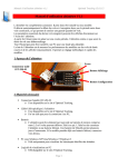
User's Manual altimeter v1.1
Optimal Tracking 01.15.15
User's Manual altimeter V1.1
The altimeter is completely autonomous. It can be installed on any model.
It automatically detects the beginning of flights and does not record the period between two
consecutive flights, which allows you to store a large quantity of flights.
The essential parameters of the last flight recorded can be displayed directly on the altimeter
screen.
From the observation of the glide over a short period, the altimeter estimates what would be
the flight duration without dethermalizing.
The entire log can be transferred to a PC for more detailed study.
The purpose of the altimeter is to measure the performance of models on short duration flights
and display it instantly. It allows methodical and quick adjustment of models.
1 - Overview of the altimeter
Screen
Male connector
JST-ZM-03
Display button
Configuration button
2 - Necessary equipment
• Female connector JST-ZH-03
o It is available on the Optimal Tracking site.
• USB cable specific to the altimeter
o It is available on the Optimal Tracking site.
o It is only useful for connection to a PC.
• Battery
o The altimeter can be supplied by any battery or rechargeable battery with
voltage of 2.5 to 6 volts that can deliver a peak of 35mA. The ideal is to
connect the altimeter to a lithium battery. A battery of 50mAh allows several
days of autonomy. If the model already has a lithium battery, connect to it.
• PC under Windows XP/Vista/Windows 7/Windows 8
o Useful only for viewing the detailed logs of altitudes.
• Viewing software on PC
o It can be downloaded from the Optimal Tracking site.
Page 1
User's Manual altimeter v1.1
Optimal Tracking 01.15.15
3 - Principle of the altimeter
Altitude (m)
Altimeter start
Climbing
Astart
-10s
Stabilization
Measurement of glide
0s
Time (s)
D1
D2
The altimeter is configured by 4 parameters:
• Astart: altitude at which the altimeter starts.
• D1: waiting time before measurement of the climb altitude.
• D2: stabilization time.
• D3: measurement duration of glide performance.
Example in F1A:
• Astart: 60m
• D1: 5s
• D2: 5s
• D3: 60s
Example in F1B:
• Astart: 10m
• D1: 35s
• D2: 5s
• D3: 60s
Example in F1C:
• Astart: 10m
• D1: 10s
• D2: 5s
• D3: 60s
Page 2
D3
User's Manual altimeter v1.1
Optimal Tracking 01.15.15
• As soon as Astart is reached, the altimeter starts. Note that it stores 10 seconds prior to
the start in the log.
• D1 seconds after, the altimeter measures the climb height.
o In F1A, D1 between 2 and 5 seconds will be chosen to measure the altitude at
the end of bunt.
o In F1B, D1 equal to the of rubber unrolling duration will be chosen. Thus, the
altitude reached when the propeller is retracted is measured.
o In F1C, D1 equal to the sum of the climb time and the bunt time will be
chosen.
• Then, over D2 seconds, the altimeter waits for the stabilization of the model.
• Then, over D3 seconds, the altimeter measures the glide performance of the model.
• Then, the altimeter records the flight log over the 3 minutes following the start.
Page 3
User's Manual altimeter v1.1
Optimal Tracking 01.15.15
4 - Handling
Getting started
When connected, the altimeter displays:
V1.1:
A=xxx:
D1=xxx:
D2=xxx:
D3=xxx:
RESET A=0:
version of the altimeter.
value of Astart in memory.
value of D1 in memory.
value of D2 in memory.
value of D3 in memory.
indicates that the altimeter initializes the current altitude at 0.
Then the symbol ". " flashes, meaning that the altimeter is ready to record a new flight.
Permanent display
A symbol flashes continuously on the screen:
.
.n
F
B
h
Altimeter ready to save a flight
(new) A new flight has just been recorded
and the altimeter is ready to record a flight
(Flight) Flight in progress. Wait until the end
of the flight
(Busy) Altimeter busy, please wait
(Height) Waiting for passing under Astart
Ready for a flight
When the symbol ". " or ".n" flashes, the altimeter is ready to record a new flight
automatically.
End of recording of a flight
When a flight has just been recorded, the symbol ".n" flashes. You can view the settings for
this flight by briefly pressing the Display button (see next page).
But, this is not required. A new flight may be registered without the last flight being viewed.
Page 4
User's Manual altimeter v1.1
Optimal Tracking 01.15.15
Display Button
Display button
• Short press: allows you to display the essential parameters of the last flight recorded.
D (display) appears and then when the button is released, the altimeter displays:
A=xxx M=xxx D/U=xxx E=xxx
o A is the altitude at the end of duration D1.
o M is the maximum altitude during the flight.
o D or U is the sinking speed during the glide expressed in mm/s (D for a drop,
U for a climb) measured during duration D3.
o E is the estimated flight duration if, at the end of duration D3, glide
performance is that measured during the duration D3.
• Long press: for sending the entire log to the computer. Refer to the part "reading the
log on a PC".
Configuration button
Configuration button
• Brief press: for considering the current altitude as altitude 0.
R (reset) appears and then when the button is released, the altimeter displays:
RESET A=0
o The altimeter resets at 0 altitude. This is not necessary because the altimeter
has an automatic reset to 0 system which operates continuously.
• Long press: for configuring the altimeter. Refer to the "Configuration" part.
Page 5
User's Manual altimeter v1.1
Optimal Tracking 01.15.15
5 - Configuration
The 4 Astart parameters, D1, D2, D3 can be modified and are kept in non-volatile memory.
Configuration button
• Press the Configuration button for 3 seconds:
o Whilst the button is pressed, R (reset) appears.
o CONFIG appears after 3 seconds. Release the button.
• The following message appears: ALT=xxx D1=xxx D2=xxx D3=xxx CLR=x
o ALT corresponds with the parameter Astart.
o D1 corresponds with the parameter D1.
o D2 corresponds with the parameter D2.
o D3 corresponds with the parameter D3.
Each character "x" of the message flashes and can be modified or confirmed.
ALT=
x
x x
Astart
D1=
x
x x
D1
D2=
x
x x
D2
D3=
x
x x
D3
CLR=
x
Y or N
• Attention:
o to enter 60 you must enter 0 6 0.
o to enter 5 you must enter 0 0 5.
Incrementing
Validation
• To increment a character, press the Display button.
• To validate a character, press the Configuration button.
• The last value (CLR) is used to clear all flights. If you validate by "Y", all flights are
cleared.
Page 6
User's Manual altimeter v1.1
Optimal Tracking 01.15.15
6 - Automatic altitude reset
The altimeter automatically resets the altitude at 0 throughout the day.
When it detects that the altitude remains constant (to the nearest + /- 2 meters) for 1 minute, it
considers that the altimeter is at ground level and resets the altitude to 0.
It is also possible to do this operation manually by briefly pressing the Configuration button.
7 - Installing the "Altimeter" software on a PC
To read and process all flights recorded by the altimeter on a PC, free software is available on
the Optimal Tracking site.
• Download from the site www.optimaltracking.com the file "install_altimeter v1.1". It
is a compressed file (ZIP file).
• Unzip the file with a utility such as WinZip.
• Go to the directory "install_altimeter v1.1".
• Run "setup.exe".
• Follow the traditional instructions for installation under Windows.
• The software will rank with the following parameters:
o Editor:
Optimal Tracking
o Name:
Altimeter
8 - Reading the log on a PC
You must have the USB cable specific to the altimeter. It is available on the Optimal Tracking
site.
Page 7
User's Manual altimeter v1.1
Optimal Tracking 01.15.15
Example of field PC: Dell tablet 8 Pro under Windows 8
• Connect the USB cable to the computer.
When the cable is connected for the first time, the PC may seek to install a driver and
connects to the Internet. Wait for the driver installation.
• Run the "Altimeter" software.
Page 8
User's Manual altimeter v1.1
Optimal Tracking 01.15.15
• Click on the "Scan" button.
• Select the COM port created by the cable. If you do not know which it is:
o Unplug the USB cable.
o Do a scan again.
o Look and see which COM port disappears. It is the one linked with your cable.
o Reconnect the cable, do a scan again and select the COM port created by the
cable.
• Click on the "Read Altimeter" button.
The following window is displayed:
• Press the Display altimeter button for 3 seconds:
o Whilst the button is pressed, D (display) appears.
o RECORD appears after 3 seconds. Release the button.
• Click on the "OK" button of the last window.
Page 9
User's Manual altimeter v1.1
Optimal Tracking 01.15.15
• Two windows appear.
o One for the altitude logs.
o One for the vertical speed logs.
Attention, the vertical speeds are calculated from altitudes. They have only a
qualitative character.
• Click and select the flights you want to display. Each flight is numbered. The more the
number is high, the more the flight is recent.
For each flight, the essential parameters are displayed in the list.
Page 10
User's Manual altimeter v1.1
Optimal Tracking 01.15.15
An average of the essential parameters of selected flights is calculated. We can thus determine
the glide performance averaged out over several flights.
Zoom on the logs
• Click on one corner of the desired zoom window and then, without releasing the
mouse button, move toward the opposite corner of the desired zoom window.
• Release the mouse button, and the zoom takes place.
Resetting the framing
• Click on one of the "Reset zoom" buttons to reset the framing of one of the 2
windows.
Printing logs
• Click on one of the "Print" buttons to print one of the 2 windows.
Saving the log in a file
• Click on "Save in file".
• Choose the directory and the name of the file in which you want to save the history of
the altimeter. The format is detailed in the "Log file format" section.
Page 11
User's Manual altimeter v1.1
Optimal Tracking 01.15.15
Reading of a backup log file
• Click on "Read file".
• Choose the directory and the name of the file to read.
Export of the logs
Click on the « Export » button in order to transfer the logs to a text or Excel file.
9 - Specifications
Version
Dimensions
Weight with 20 cm of cable
Weight with 2 cm of cable
Connector
Cable length
Allowable input voltage
Peak intensity
Average consumption
Type of altimeter
Number of altitude recordings
Flight record duration
Recorded time before starting
Maximum number of flights recorded
Maximum value of D1
Maximum value of D2
Maximum value of D1+D2+D3
Red wire
Black wire
Blue wire
Setting of the serial port
1.1
19.3 x 12.2 x 4.7 mm (excluding cables)
2.0 grams
1.2 grams
JST-ZM-03
20 cm
2.5 to 6.0 Volts
35 mA
1 mA
MEMS pressure sensor
Temperature compensated
Resolution 30 cm
4 per second
180 seconds
10 seconds
85
80
80
180
Power supply
Ground
Serial transmission
115200/8/N/1
Page 12
User's Manual altimeter v1.1
Optimal Tracking 01.15.15
10 - Log file format
The format of the log file is exactly the same as the one of the data received on the serial port.
By pressing the Display button for 3 seconds, data is received in the format described below.
It is therefore very easy to create software able to read the altimeter log.
Here is an example of a file:
$STA
Altimeter Flight Record
Parameters Alt1=60, D1=5, D2=5, D3=60
Alt_record = 13225 cm
N_flights = 9
$FLIGHT 1
A_bunt=7640
A_max=8270
Perf=-1178
T_est=69
N_point=320
0.0 4790
0.250 4840
0.500 4740
0.750 4720
……
179.750 4530
$FLIGHT 2
A_bunt=9440
A_max=9590
Perf=-396
T_est=239
N_point=320
0.0 5070
0.250 5160
0.500 5140
…..
79.0 8830
79.250 8730
79.500 8780
179.750 8810
$END
Page 13
User's Manual altimeter v1.1
Optimal Tracking 01.15.15
Description of contents
$STA:
beginning of file
Altimeter Flight Record: comment
Parameters Alt1 =60, D1 =5, D2 =5, D3 =60 : value of 4 configuration settings
Alt_record: absolute altitude at the time of the transfer of data on the serial port
N_flights:
number of flights recorded
$FLIGHT i: beginning of the flight i
A_bunt:
value in cm of the climbing height
A_max:
value in cm of the maximum height on the flight
Perf:
value in mm/s for glide performance
T_est:
value in seconds of the time-of-flight estimated
N_point:
recording number in the flight
0.0 4790:
time (s) altitude (cm)
0.250 4840: time (s) altitude (cm)
0.500 4740: time (s) altitude (cm)
0.750 4720: time (s) altitude (cm)
……
179.750 4530: time (s) altitude (cm)
$FLIGHT j: beginning of the flight j
…..
$END:
end of file
Optimal Tracking
360 chemin de Pauli
13760 Saint Cannat - France
Tel: +33 (0) 4 42 38 05 32
www.optimaltracking.com
The information contained in this document are subject to change without notice. Optimal Tracking reserves
the right to change or improve its products and to make modifications to this content without prior warning. To
get the latest updates to this document, please consult the site www.optimaltracking.com
The trademarks mentioned in this manual are the property of their owners.
Page 14