Download PLDaniels IRM User manual
Transcript
PLDaniels IRM User manual
v005R2 - http://nqrc.com
May 15, 2009
1
Contents
1 Introduction
3
2 Introduction to cell internal resistance
2.1 Why does it matter . . . . . . . . . .
2.2 Testing method . . . . . . . . . . . .
2.3 Factors effecting resistance readings . .
2.3.1 Contact corrosion . . . . . . .
2.3.2 Cell temperature . . . . . . . .
2.3.3 Cell charge . . . . . . . . . . .
2.3.4 Cell age . . . . . . . . . . . .
2.3.5 Cell capacitance and impedence
2.4 Choosing appropriate tests . . . . . . .
.
.
.
.
.
.
.
.
.
3
3
3
4
4
4
4
4
4
5
.
.
.
.
5
5
5
5
5
.
.
.
.
.
.
.
.
6
6
6
7
8
8
9
9
10
3 Testing methodology
3.1 IRM tests . . . . . . . . .
3.1.1 1 ohm test . . . .
3.1.2 0.5 ohm test . . .
3.1.3 0.5 ohm 1kHz test
4 IRM operation
4.1 Precautions . . . . . . .
4.2 Power on . . . . . . . .
4.3 Testing / Details display
4.4 Capacity setting . . . .
4.5 Summary evaluation . .
4.6 Power off . . . . . . . .
4.7 Hints, Tips and FAQ . .
4.8 Errors / Faults . . . . .
.
.
.
.
.
.
.
.
.
.
.
.
.
.
.
.
.
.
.
.
.
.
.
.
.
.
.
.
.
.
.
.
.
.
.
.
.
.
.
.
.
.
.
.
.
.
.
.
.
.
.
.
.
.
.
.
.
.
.
.
.
.
.
.
.
.
.
.
.
.
.
.
.
.
.
.
.
.
.
.
.
.
.
.
.
.
.
.
.
.
.
.
.
.
.
.
.
.
.
.
.
.
.
.
.
.
.
.
.
.
.
.
.
.
.
.
.
.
.
.
.
.
.
.
.
.
.
.
.
.
.
.
.
.
.
.
.
.
.
.
.
.
.
.
.
.
.
.
.
.
.
.
.
.
.
.
.
.
.
.
.
.
.
.
.
.
.
.
.
.
.
.
.
.
.
.
.
.
.
.
.
.
.
.
.
.
.
.
.
.
.
.
.
.
.
.
.
.
.
.
.
.
.
.
.
.
.
.
.
.
.
.
.
.
.
.
.
.
.
.
.
.
.
.
.
.
.
.
.
.
.
.
.
.
.
.
.
.
.
.
.
.
.
.
.
.
.
.
.
.
.
.
.
.
.
.
.
.
.
.
.
.
.
.
.
.
.
.
.
.
.
.
.
.
.
.
.
.
.
.
.
.
.
.
.
.
.
.
.
.
.
.
.
.
.
.
.
.
.
.
.
.
.
.
.
.
.
.
.
.
.
.
.
.
.
.
.
.
.
.
.
.
.
.
.
.
.
.
.
.
.
.
.
.
.
.
.
.
.
.
.
.
.
.
.
.
.
.
.
.
.
.
.
.
.
.
.
.
.
.
.
.
.
.
.
5 Specifications
11
5.1 Electronic operational limits . . . . . . . . . . . . . . . . . . . . 11
5.2 Physical specifications . . . . . . . . . . . . . . . . . . . . . . . 11
6 IRM Servicing
12
6.1 Reflashing . . . . . . . . . . . . . . . . . . . . . . . . . . . . . 12
7 Sample readings
12
2
1
Introduction
For a long time, lipo pack makers have been content to deliver to us a single
rating for performance of their packs, the ’C’ rating. Unfortunately for us this
C rating is near worthless due to each maker choosing their own basis on which
to define what C is. The PLDaniels IRM has been created to give us the ability
to make an informed deteminiation of what the true cell and pack ratings by
providing a far more useful measure, the cell internal resistance.
Let it be stated that there is no perfect test for cell internal resistance. The
IRM has been built to allow cells to be tested under a known set of loads which
will facilitate comparisons.
2
2.1
Introduction to cell internal resistance
Why does it matter
Once we have an idea of the internal resistance of a cell we can then use that to
determine how efficient our power setup is as well as knowing how much power
is being turned to heat in the battery pack and additionally know how much the
voltage can potentially drop under load.
2.2
Testing method
To determine the internal resistance of a cell, the cell is connected to a purely
resistive load of known value (eg 1.0 ohms). The voltage of the cell before the
3
load is attached is recorded (eg, 4.20V) then the voltage of the cell when attached
to the load is recorded (eg, 4.00V). Knowing the difference of the voltages and
the load resistance the cell internal resistance can hence be derived;
2.3
Factors effecting resistance readings
Unfortunately due to the nature of batteries, cells exhibit characteristics of resistance, capacitance and inductance of which all contribute to the measured
internal resistance. Internal resistance can vary considerably even within the
same cell, this makes the task of determining the internal resistance a lot harder,
however by keeping other variable factors constant one can produce results that
allow comparisons.
2.3.1
Contact corrosion
While not actually part of the cell itself, having dirty contacts to the cells can
make a noticable difference in the resistance. Wiping clean the contacts can
improve contact resistance by 10 or more milliohms.
2.3.2
Cell temperature
For many cell chemistries the resistance of the pack decreases initially from room
temperature to a certain level (perhaps 45’C) after which the resistance of the
pack will increase again. Lithium cells in particular suffer poor cell resistance
near 0’C.
2.3.3
Cell charge
Generally the closer to a full charge a cell is the lower the internal resistance
2.3.4
Cell age
As cells become older their internal resistance tends to increase
2.3.5
Cell capacitance and impedence
Under constant current DC loads, the cell capacitance and impedence effects
tend to be negligable, however with oscillating loads (eg, 1kHz ESC switching)
the cell can appear to have different resistances.
4
2.4
Choosing appropriate tests
Is there a perfect test for the cell internal resistance? No. The IRM was not
built to persue the holy-grail of testing. The IRM has been built to provide a
convenient way of applying three (3) common tests that will allow you to compare
cells and give insight into cell performance.
3
Testing methodology
In order for a measurement to be meaningful, the testing methodology needs
to be clearly stated to allow others to perform the same tests. Each person
may have a preferred testing method that they feel more correctly reflects real
world usage, however this will not be discussed here, rather this section is about
detailing the tests already chosen. The IRM has been preprogrammed to perform
three (3) different tests. Each test is performed after a two (2) second interval.
3.1
IRM tests
3.1.1
1 ohm test
Load: 1.0 ohm +/-0.01 ohms (0.99 to 1.01)
Duration: Less than 1 second.
Typical current: 4A for a fully charged lipo
3.1.2
0.5 ohm test
Load: 0.5 ohms +/-0.01 ohms (0.49 to 0.51)
Duration: Less than 1 second.
Typical current: 8A for a fully charged lipo
This test should produce the highest internal resistance reading towards the
end of the test
3.1.3
0.5 ohm 1kHz test
Load: 0.5 ohms +/-0.01 ohms (0.49 to 0.51)
Duration: 1.0 seconds +/- 0.1 seconds
Duty: 50%
Typical current: 4A average for a fully charged lipo
This test typically will produce the lowest internal resistance reading
5
4
IRM operation
4.1
Precautions
1. Do not leave a cell connected to the IRM for more than one or two minutes.
2. Be aware that although the IRM only takes small samples from the battery
pack, the voltage will be reduced. Make sure you check your pack balance
3. Avoid plugging the cell in backwards (reverse polarity). The IRM can cope
with a reversed connection for a few seconds but it’s still better not to do
it in the first place.
4. Do not connect more than 5V to the cell inputs, again, the IRM can cope
for a few seconds but it’s best not to do it!
4.2
Power on
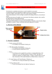
Connect either a 2S lipo or voltage source between 8.0V and 15V (12V is the
preferred maximum but the IRM can cope with up to 15V) to the IRM via the
3 pin header on the left-hand center side with the pin closest to the top of the
screen being positive and the bottom pin being negative(ground). The center
pin is disconnected and is used purely as a placement holder. The IRM is reversepolarity protected, so if you connect the battery the wrong way around there will
be no damage.
The IRM will display a short message on the screen, namely giving the current
firmware version before commencing to the Testing screen
6
4.3
Testing / Details display
Note: Always clean the test contacts before testing a new
cell. Even the slightest amount of grime will considerably effect the measured values.
While there is no battery connected to either of the two pin terminals on the
right hand side of the IRM, the details screen will display “No battery”.
Note: Only use one cell connector at a time. Do not attempt
to use both the 2.0 and 2.54mm connectors simultaneously.
On connecting a cell the IRM will begin to perform the three (3) load tests and
determine the internal resistance, updating the details display for each. After all
three (3) tests are complete you can commence to set the cell capacity. It will
take approximately 10 seconds to finish each round of testing, a lot of cells may
require two or three passes to stabilize.
The IRM will continue to test the cell indefinitely while in the details display
mode.
7
4.4
Capacity setting
After the test values have started to stabilize pressing the left button increases
the cell capacity in 50mAh lots. Holding down the button will make the IRM
auto increment the value until the button is released.
4.5
Summary evaluation
8
Once the cell capacity has been set, the IRM will provide a series of five (5)
voltage drop summaries for the cell that has been tested.
The IRM displays the available current, power, efficiency and equivalent ’C’
rating for voltage drops between 0.1 and 0.5V. For lipoly cells, the 0.3V drop
setting should be considered as a good benchmark for the cell (translating to a
0.9V drop on a 3S pack).
Notice that the efficiency value drops off as the voltage drop increases, this
is because more power is being burned up as heat within the cell. A theoretical
perfect cell would have a zero voltage drop at all loads, unfortunately such a
thing doesn’t exist.
Press the right button to step to the next voltage drop.
After the 0.5V drop summary the IRM will return to the details display and
commence testing the cell again.
If you wish to test another cell with the same mAh capacity, change the cell
over before pressing the button again, this way the mAh setting in the IRM will
be preserved.
4.6
Power off
When all the testing is complete, remove the cell under test from the 2 pin header
then remove the power from the 3 pin header.
4.7
Hints, Tips and FAQ
Hints and tips
• Measure your cells at a known room temperature
• Measure your cells at a consistent voltage / charge
• Always clean the IRM cell test contacts between tests
• Allow the IRM about 10~30 seconds to get stable results from the cell
FAQ
1. Why use 1.0 and 0.5 ohm loads, why not X.y ohms?
(a) There are several factors involved in why the IRM uses 1.0 and 0.5
ohm loads
i. Availability of components with sufficient precision, reasonable
costs and ample power dissipation
9
ii. Simplicity of the maths involved in deriving the internal resistance
iii. 0.5 ohm load is simply two 1.0 ohm loads in parallel
iv. Sufficiently large load (4A and 8A) without being too weak or
too severe
2. The IRM results don’t match the results I obtained from my charger, why?
(a) A multitude of possible reasons for this
i. Chargers are putting power into a pack, not depleting
ii. Chargers use a different current setting (varies for the duration
of the charge too)
iii. Chargers may not always account for resistance the leads being
used
iv. Chargers are likely using an averaging algorithm for the resistance
measured during the entire charge cycle
3. The 1.0 ohm test produces an internal resistance that is higher than the
0.5 ohm test
(a) Due to the way the voltage sensing occurs in the electronics of the
IRM, the 0.5 ohm test actually produces a more accurate reading
with twice the precision of the 1.0 ohm test, subsequently the 1.0
ohm test may exceed the 0.5 ohm test by a couple of milliohms in
some situations. Often after a 30 second test period both the 1.0
and 0.5 ohm test results will converge to read very similar.
4.8
Errors / Faults
1. No display
Check that the supply voltage to the IRM is between 7.5V and 15V, check
also that the center pin is positive and one of the outer pins is ground.
2. Battery not detected
Check that the polarity of the cell is the correct way around. The positive
pin should be towards the top of the IRM
3. Open cell voltage doesn’t match voltage measured with multimeter
This can happen if the voltage is below 7.5V or above 15V to the IRM.
Also it’s quite possible the multimeter is not correctly calibrated
10
4. Milliohms readings fluctuate dramatically
Contacts for the cell connection are likely dirty or frayed. Clean with a 3M
microcloth or similar.
5. Smoke escaping from IRM
Disconnect everything from the IRM, visually inspect the back of the board
to see where the smoke came from. If the IRM is no longer operational,
contact PLDaniels / NQRC.
Possible causes are excessive over-voltage on the input (20V+), short circuit on the board or outright bad luck.
5
5.1
Specifications
Electronic operational limits
Supply voltage: 8 - 15V (8-12V for optimal accuracy)
Cell compatibility: Lithium polymer, Lithium Ion, LiFeO4, NiMH, NiCd
Cell test voltage minimum: 1.0V
Cell test voltage maximum: 5.0V
Cell resistance minimum: 4 milliohms
Cell resistance maximum: 999 milliohms
Cell resistance precision: +/-2milliohms
Minimum temperature: 0’C (32’F)
Maximum temperature: 40’C (104’F)
5.2
Physical specifications
Size: 85 x 40 x 40mm
Weight: 150g
Construction: Single 85 x 40 PCB with modular LCD panel attachment
shrink-wrapped.
Cell test input connectors: 2 pin 2.54mm (0.1”) and 2 pin 2.00mm
Supply input connector: 3 pin 2.54mm (0.1”) pitch connector, center pin
positive, two outer pins ground/negative.
11
6
6.1
IRM Servicing
Reflashing
The IRM can be flashed with a new firmware via the 6 pin ISP head located in
the middle of the board adjacent to the microcontroller (Atmel AVR mega48).
7
Sample readings
12


