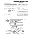
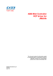
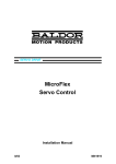
1
UniOP eTOP Series 500 Operating Instructions Basic Users Manual for eTOP Series 500 Touchscreen Products Exor International S.p.A. MANUGENETOP5xx UniOP Ver. 1.04 Copyright © 2011-2012 Exor International S.p.A. Verona, Italy Subject to change without notice The information contained in this document is provided for informational purposes only. While efforts were made to verify the accuracy of the information contained in this documentation, it is provided as is without warranty of any kind. Third-party brands and names are the property of their respective owners. www.uniop.com MANUGENETOP5xx UniOP Operating Instructions VER 1.04 2 Table of Contents Table of Contents Introduction .............................................................................................................................................4 Safety Guide ...........................................................................................................................................5 1 Product Overview ................................................................................................................................6 2 Standards and Approvals ....................................................................................................................7 3 Technical Speci!cations ......................................................................................................................8 4 Technical Data ...................................................................................................................................10 4.1 Dimensions .....................................................................................................................................14 4.2 Installation Environment .................................................................................................................16 4.3 Installation Procedure .....................................................................................................................17 5 Connections.......................................................................................................................................18 5.1 Serial Port .......................................................................................................................................20 5.2 Ethernet Port ..................................................................................................................................21 6 Power Supply, Grounding and Shielding ...........................................................................................22 7 Battery ...............................................................................................................................................23 8 Cleaning Faceplates ..........................................................................................................................24 9 Getting Started ..................................................................................................................................24 10 System Settings...............................................................................................................................25 11 LED Indicator on Front Panel ..........................................................................................................27 12 Unpacking and Packing Instructions ...............................................................................................28 MANUGENETOP5xx UniOP Operating Instructions VER 1.04 3 Introduction Introduction The operational guidelines described below is information which relates to the device, installation, transportation, storage, assembly, use and maintenance. This Operating Instruction describes the main features of the UniOP operator panels. The Manual refers to the following models: eTOP504 eTOP506 eTOP507 eTOP510 eTOP512 eTOP513 eTOP515 Operator interface with TFT color 4.3 display touchscreen Operator interface with TFT color 5.7 display touchscreen Operator interface with TFT color 7 widescreen display touchscreen Operator interface with TFT color 10.4 display touchscreen Operator interface with TFT color 12.1 display touchscreen Operator interface with TFT color 13.3 widescreen display touchscreen Operator interface with TFT color 15 display touchscreen MANUGENETOP5xx UniOP Operating Instructions VER 1.04 4 Safety Guide Safety Guide The manual contains safety standards that must be respected for the personal safety and to avoid damage. Indications of attention are divided into three levels of severity: DANGER: indicates a failure to observe safety rules and such failure may cause death or serious injuries. ! DANGER ATTENTION: indicates a failure to observe safety rules and that de!ciency may cause damage. ! ATTENTION CAUTION: indicates a failure to observe safety rules and that de!ciency may cause defects to the equipment or inconsistencies. E CAUTION MANUGENETOP5xx UniOP Operating Instructions VER 1.04 5 Product Overview 1 Product Overview The UniOP eTOP Series 500 HMI products combine state-of-the-art features and top performance with an oustanding design. They are the ideal choice for all demanding HMI applications including factory and building automation. The eTOP Series 500 HMI panels have been designed to run the JMobile software. · · · · · · · · · · · · · · · JMobile runtime included. Full compatibility with JMobile Studio. Full vector graphic support. Native support of SVG graphic objects. Trasparency and alpha blending. Full object dynamics: control visibility and transparency, move, resize, rotate any object on screen. Change properties of basic and complex objects. TrueType fonts. Multilanguage applications. Easily create and manage your applications in multiple languages to meet global requirements. Far East languages are supported. Tools available in JMobile Studio support easy third-party translations and help reducing development and maintenance costs of the application. Data display in numerical, text, bargraph, analog gauges and graphic image formats. Rich set of state-of-the-art HMI features: data acquisition, alarm handling, scheduler and timed actions (daily and weekly schedulers, exception dates), recipes, users and passwords, RSS feeds, rotating menus. Includes support for a wide range of communication drivers for Factory systems. Multiple drivers communication capability. Remote monitoring and control. Client-Server functionality. Off-line simulation with JMobile Studio. Powerful scripting language for automating HMI applications. Script debugging improves ef!ciency in application development. Rich gallery of vector symbols and objects. Project templates. Optional plug-in modules for !eldbus systems, I/O and controllers. MANUGENETOP5xx UniOP Operating Instructions VER 1.04 6 Standards and Approvals 2 Standards and Approvals The products have been designed for use in an industrial environment in compliance with the 2004/108/ EC EMC Directive. The products have been designed in compliance with: EN 61000-6-4 EN 55011 Class A EN 61000-6-2 EN 61000-4-2 EN 61000-4-3 EN 61000-4-4 EN 61000-4-5 EN 61000-4-6 The installation of these devices into the residential, commercial and light-industrial environments is allowed only in the case that special in measures are taken in order to ensure conformity to EN 61000-6-3. The products are in compliance with the Restrictions on Certain Hazardous Substances (RoHS) Directive 2002/95/EC In compliance with the above regulations the products are CE marked. Product Identication The product may be identi!ed through a plate attached to the rear cover. You will have to know the type of unit you are using for correct usage of the information contained in the guide. An example of this plate is shown in the !gure below: eTOP504 ETOP504U101 05/11 09994847559 040100A01000000 product model name product part number month/year of production serial number version id of the product MANUGENETOP5xx UniOP Operating Instructions VER 1.04 7 Standards and Approvals 3 Technical Speci!cations Touch screen technology Resistive Back-up battery Fuse 3V 50mAh Lithium, rechargeable, not user-replaceable, model VL2330. Automatic Serial Port RS-232, RS-485, RS-422 software con!gurable User memory Recipe memory Hardware clock Accuracy RTC (at 25°C) Flash 128Mb Flash Clock/Calendar with back-up battery <100ppm Environmental conditions Operating temperature (surrounding air temperature) Storage temperature Operating and storage humidity Vibrations Shock Protection class 0 ÷ +50°C EN60068-2-14 -20 ÷ +70°C 5 ÷ 85 % RH not-condensing 5 ÷ 9 Hz, 7 mm p-p 9 ÷ 150 Hz, 1 g ± 50 g, 11 ms, 3 pulses per axis IP66 front panel * EN60068-2-14 EN60068-2-30 EN 60068-2-6 EN60068-2-27 EN 60529 * The front face of the UniOP unit, installed in a solid panel, has been tested using conditions equivalent to the standards shown in the Environmental conditions. Even though the level of resistance UniOP unit is equivalent to these standards, oils that should have no effect on the UniOP can possibly harm the unit. This can occur in areas where either vaporized oils are present, or where low viscosity cutting oil are allowed to adhere to the unit for long periods of time. If the front face protection sheet on the UniOP becomes peeled off, these conditions can lead to the ingress of oil into the UniOP and separate protection measures are suggested. If the installation gasket is used for a long period of time, or if the unit and its gasket are removed from the panel, the original level of the protection cannot be guaranteed. MANUGENETOP5xx UniOP Operating Instructions VER 1.04 8 Standards and Approvals Electromagnetic Compatibility (EMC) Radiated disturbance test Electrostatic discharge immunity test Class A 8 kV (air electrostatic discharge) 4 kV (contact electrostatic discharge) EN 55011 EN 61000-4-2 Radiated, radio-frequency, electromagnetic !eld immunity test 80 MHz ÷ 1 GHz, 10V/m 1,4 GHz ÷ 2 GHz, 3 V/m 2 GHz ÷ 2.7 GHz, 1 V/m ± 2 KV DC power port ± 1 KV signal line ± 0,5 KV DC power port (line to earth) ± 0,5 KV DC power port (line to line) ± 1 KV signal line (line to earth) EN 61000-4-3 Burst immunity test Surge immunity test Immunity to conducted disturbances inducted by radiofrequency !eld 0.15 ÷ 80 MHz, 10V EN 61000-4-4 EN 61000-4-5 EN 61000-4-6 Voltage dips, short interruptions and voltage variations immunity test Port: AC mains; Level: 100% duration: 1 cycle and 250 cycles (50Hz); 40% duration: 10 cycles (50Hz); 70% duration: 25 cycles (50Hz); Phase: 0°-180° Test executed on the 230Vac side of the Sitek Power Supply EN 61000-4-11 Durability information Backlight service life (LED type) 40000 Hrs. or more (Time of continuos operation until the brightness of the backlight reaches 50% of the rated value when the sorrounding air temperature is 25°C) - see Note 1 Front foil (without directly exposure to sunlight or UV ray) 10 years if the surrounding air temperature is 25°C UV Resistance Indoor applications: After 300 hours cycled humidity in QUV accelerated weathering, some yellowing and brittleness may be present. - see Note 2. Touch screen reliability > 1 milion operations Note 1: Extended use in environments where the surrounding air temperature is 40°C or higher may degrade backlight quality/reliability/durability. Note 2: Solvent resistance: Contact for 1/2 hour at 21°C, No visible effect: Acetone, Butyl Cellosolve, Cyclohexanone, Ethyl Acetate, Hexane, Isopropyl Alcohol, MEK, Methylene Chloride, Toluene, Xylene Contact for 24 hours at 49°C, No visible effect: Coffee, Ketchup, Lemon Juice, Mustard (slight yellow stain), Tea, Tomato juice. MANUGENETOP5xx UniOP Operating Instructions VER 1.04 9 Technical Data 4 Technical Data Model Display / Backlight Colors Resolution eTOP504 eTOP506 TFT Color / LED TFT Color / LED 64K 64K 480X272 320x240 Diagonal (inches) 4.3 5.7 Dimming yes yes 128MB 128MB User memory !ash SD card slot Recipe memory Serial Port yes Yes. Flash memory storage limited only by available memory yes Yes. Flash memory storage limited only by available memory RS-232,RS-485 RS-422 DB9 female software con!gurable RS-232,RS-485 RS-422 DB9 female software con!gurable 2 10/100 Mbit with integrated switch 2 10/100 Mbit with integrated switch USB port 1 Host interface version 2.0 and 1.1 2 Host interface, 1 version 2.0, 1 version 2.0 and 1.1 Expansion slot 1 Optional Plugin 2 Optional Plugin Ethernet port Battery Real Time Clock Voltage rechargeable rechargeable yes yes 18-30VDC 18-30VDC Current rating (at 24VDC) 0.4A 0.65A Weight 1 Kg 1 Kg MANUGENETOP5xx UniOP Operating Instructions VER 1.04 10 Technical Data Model Display / Backlight Colors Resolution Diagonal (inches) Dimming User memory !ash SD card slot Recipe memory Serial Port eTOP507 eTOP510 TFT Color / LED TFT Color / LED 64K 800X480 7 widescreen 64K 800x600 10.4 yes yes 128MB 128MB yes yes Yes. Flash memory storage limited only by available memory Yes. Flash memory storage limited only by available memory RS-232,RS-485 RS-422 DB9 female software con!gurable RS-232,RS-485 RS-422 DB9 female software con!gurable Ethernet port 2 10/100 Mbit with integrated switch 2 10/100 Mbit with integrated switch USB port 2 Host interface, 1 version 2.0, 1 version 2.0 and 1.1 2 Host interface, 1 version 2.0, 1 version 2.0 and 1.1 Expansion slot Battery Real Time Clock Voltage 2 Optional Plugin rechargeable yes 18-30VDC 2 Optional Plugin rechargeable yes 18-30VDC Current rating (at 24VDC) 0.7A 1A Weight 1 Kg 2.1 Kg MANUGENETOP5xx UniOP Operating Instructions VER 1.04 11 Technical Data Model Display / Backlight Colors Resolution eTOP512 eTOP513 TFT Color / LED TFT Color / LED 64K 64K 800X600 1280x800 Diagonal (inches) 12.1 Dimming yes yes 128MB 128MB yes yes User memory !ash SD card slot Recipe memory Serial Port 13.3 widescreen Yes. Flash memory storage limited only by available memory Yes. Flash memory storage limited only by available memory RS-232,RS-485 RS-422 DB9 female software con!gurable RS-232,RS-485 RS-422 DB9 female software con!gurable Ethernet port 2 10/100 Mbit with integrated switch 2 10/100 Mbit with integrated switch USB port 2 Host interface, 1 version 2.0, 1 version 2.0 and 1.1 2 Host interface, 1 version 2.0, 1 version 2.0 and 1.1 Expansion slot Battery 2 Optional Plugin 2 Optional Plugin rechargeable rechargeable yes yes 18-30VDC 18-30VDC Current rating (at 24VDC) 1.2A 1.2A Weight 2.8 Kg 2.8 Kg Real Time Clock Voltage MANUGENETOP5xx UniOP Operating Instructions VER 1.04 12 Technical Data Model Display / Backlight Colors Resolution eTOP515 TFT Color / LED 64K 1024X768 Diagonal (inches) 15 Dimming yes User memory !ash 128MB SD card slot Recipe memory Serial Port yes Yes. Flash memory storage limited only by available memory RS-232,RS-485 RS-422 software con!gurable Ethernet port 2 10/100 Mbit with integrated switch USB port 2 Host interface, 1 version 2.0, 1 version 2.0 and 1.1 Expansion slot Battery Real Time Clock Voltage 2 Optional Plugin rechargeable yes 18-30VDC Current rating (at 24VDC) 1.40A Weight 3.5 Kg MANUGENETOP5xx UniOP Operating Instructions VER 1.04 13 Technical Data 4.1 Dimensions Cut out MODEL A B C eTOP504 149mm/5.86 109mm/4.29 136mm/5.35 D 96mm/3.78 E F 56mm/2.40 4mm/0.16 MANUGENETOP5xx UniOP Operating Instructions VER 1.04 14 Technical Data Cut out D E F 176mm/6.90 136mm/5.35 47mm/1.85 4mm/0.16 147mm/5.79 176mm/6.90 136mm/5.35 47mm/1.85 4mm/0.16 287mm/11.3 232mm/9.13 276mm/10.86 221mm/8.70 56mm/2.20 4mm/0.16 eTOP512 336mm/13.22 267mm/10.51 326mm/12.83 256mm/10.07 56mm/2.20 4mm/0.16 eTOP513 336mm/13.22 267mm/10.51 326mm/12.83 256mm/10.07 56mm/2.20 4mm/0.16 eTOP515 392mm/15.43 307mm/12.08 381mm/15 296mm/11.65 60mm/2.36 4mm/0.16 MODEL A B eTOP506 187mm/7.36 147mm/5.79 eTOP507 187mm/7.36 eTOP510 C MANUGENETOP5xx UniOP Operating Instructions VER 1.04 15 Technical Data 4.2 Installation Environment The equipment is not intended for continuous exposure to direct sunlight. This might accelerate the aging process of the front panel !lm. The equipment is not intended for installation in contact with corrosive chemical compounds. Check the resistance of the front panel !lm to a speci!c compound before installation. Do not use tools of any kind (screwdrivers, etc.) to operate the touch screen of the panel. In order to meet the front panel protection classi!cations, proper installation procedure must be followed: · the borders of the cutout must be "at · screw up each !xing screw until the plastic bezel corner get in contact with the panel. · the cutout for the panel must be of the dimensions indicated in this manual. The IP66 is guaranteed only if: · max deviation from the plane surface to the cut-out: O0.5mm · thickness of the case where is mounted the equipment: from 1,5mm to 6mm · max surface roughness where the gasket is applied: O120 um Applying the gasket The gasket should be applied on the rear of the frame. Fig. 4.1: eTOP504, eTOP506, eTOP507 Fig. 4.2: eTOP510, eTOP512, eTOP513, eTOP515 A. Gasket B. Installation cut-out MANUGENETOP5xx UniOP Operating Instructions VER 1.04 16 Technical Data 4.3 Installation Procedure Place the !xing brackets as shown in !gure (Fig. 4.3). Fig. 4.3 E CAUTION Screw each !xing screw until the bezel corner gets in contact with the panel. MANUGENETOP5xx UniOP Operating Instructions VER 1.04 17 Connections 5 Connections eTOP504 Fig. 5.1 1. Serial Port 2. 2x Ethernet Port 3. USB Port 4. Power Supply 5. Expansion slot for Plugin module 6. SD Card Slot MANUGENETOP5xx UniOP Operating Instructions VER 1.04 18 Connections eTOP5xx Fig. 5.2 1. Serial Port 2. 2x Ethernet Port 3. 2x USB Port 4. Power Supply 5. 2x Expansion slot for Plugin module 6. SD Card Slot MANUGENETOP5xx UniOP Operating Instructions VER 1.04 19 Connections 5.1 Serial Port The serial port is used to communicate with the PLC or with another type of controller. Different electrical standards are available for the signals in the PLC port connector: RS-232, RS-422, RS-485. The serial port is software programmable. Make sure you select the appropriate interface in the programming software. RS-422, RS-485 RS-232 Pin 1 2 3 4 5 6 7 8 9 Description GND TX RX +5V output CTS RTS SERIAL PORT Pin 1 2 3 4 5 6 7 8 9 Description GND CHACHB+5V output CHB+ CHA+ To operate in RS485 pins 4-3 and 8-7 must be connected externally. The communication cable must be chosen for the type of device being connected. MANUGENETOP5xx UniOP Operating Instructions VER 1.04 20 Connections 5.2 Ethernet Port The Ethernet port have two status indicators. Please see description in !gure. 1 OFF: Valid link has NOT been detected ON: Valid link has been detected 8 ON: No activity BLINKING: Activity MANUGENETOP5xx UniOP Operating Instructions VER 1.04 21 Power Supply, Grounding and Shielding 6 Power Supply, Grounding and Shielding The power supply terminal block is shown in the !gure below. Fig. 6.1 Note: Ensure that the power supply has enough power capacity for the operation of the equipment. The unit must always be grounded to earth. Grounding helps limit the effects of noise due to electromagnetic interference on the control system. Earth connection will have to be done using either the screw or the faston terminal located near the power supply terminal block. A label helps identify the ground connection. Also connect to ground the terminal 3 on the power supply terminal block. The power supply circuit may be "oating or grounded. In the latter case, connect to ground the power source common as shown in !gure (see below) with a dashed line. When using the "oating power scheme, note that the panes internally connects the power common to ground with a 1MW resistor in parallel with a 4,7nF capacitor. The power supply must have double or reinforced insulation. The suggested wiring for the power supply is shown below. Fig. 6.2 All the electronic devices in the control system must be properly grounded. Grounding must be performed according to applicable regulations. MANUGENETOP5xx UniOP Operating Instructions VER 1.04 22 Battery 7 Battery These devices are equipped with rechargeable Lithium battery, not user-replaceable. The following information is maintained by the battery: · hardware real-time clock (date and time) Charge: At !rst installation must be charged for 48 hours. When the battery is fully charged, it ensures a period of 3 months of data back-up at 25°C. Battery Fig. 7.1: eTOP504 Battery Fig. 7.2: eTOP506, eTOP507 eTOP510, eTOP512, eTOP513, eTOP515 ! ATTENTION Dispose of batteries according to local regulations. MANUGENETOP5xx UniOP Operating Instructions VER 1.04 23 Cleaning Faceplates / Getting Started 8 Cleaning Faceplates The equipment must be cleaned only with a soft cloth and neutral soap product. Do not use solvents. 9 Getting Started UniOP 500 series panels must be programmed with the programming software JMobile Studio. To program a panel you will have to connect the panel to a personal computer running JMobile Studio software package; the panel must be in Con!guration mode to be programmed. UniOP 500 series units are programmed via the Ethernet interface. The software package JMobile is a WindowsTM application and must be properly installed. JMobile uses the personal computer Ethernet interface to communicate with the target device. Make sure that the proper !rewall policy is con!gured in order to allow JMobile Studio to access the network. The version of the JMobile Studio used must be compatible with the JMobile runtime version installed on the panel to be programmed. MANUGENETOP5xx UniOP Operating Instructions VER 1.04 24 System Settings 10 System Settings The UniOP panels have a system settings tool to allow basic and preliminary settings to the unit. The System settings tool comes in the shape of a rotating menu with navigation buttons at top and bottom to scroll between the available options. The tool is shown in the picture below. On the left side the several components and functions are highlighted and, per each of them, the right side (Info pane) shows the information about the current version, when applicable. In the picture below it is showed the version of the Main OS component. System Settings has two operating modes: User Mode and System Mode. The difference between them is only in the number of available options. System settings in User Mode is activated from the context menu. The context menu can be recalled by clicking and holding any unused area of the touchscreen for a few seconds. Default holding time is 2 sec. Holding time is a runtime parameter that can be changed. System settings in System Mode can be activated with the so-called Emergency system access procedure. This procedure consist in tapping in the middle of the touchscreen with a !nger at a high frequency while the systemis powering up. The Emergency procedure can only be accessed at powerup. MANUGENETOP5xx UniOP Operating Instructions VER 1.04 25 System Settings User mode is the simplest possible interface where a generic user can get access to the basic settings of the panel: Calibrate Touch: Network: Time: Display settings: BSP settings: Plugin list: allows to calibrate the touch screen interface allows to change the options of the panel on-board network card allows to change the panel RTC options, including time zone and DST automatic backlight turnoff and brightness adjustment allows to check the BSP (Board Support Package) version (example 2.37), check the operating hours timers for the unit and separately for the backlight, enable/disable the buzzer, enable/disable the use of the low battery front LED indicator allows to check the presence of optional plugin modules installed. System Mode is the complete interface of the System Settings tool where all the available options are available; in addition to the options available in the User Mode we have the following important options: Format Flash: Resize Image Area: allows to format the internal panel !ash disk allows to resize the !ash portion reserved to store the splash screen image displayed by the unit at power up; default settings are normally ok for all the units Download Con!guration OS: allows to check current version and upgrade the back-up operating system, see below in the next chapter for additional details Download Main OS: allows to check current version and upgrade the main operating system, see below in the next chapter for additional details Download Splash Image: allows changing the splash screen image displayed by the unit at power up; the image should be provide in a speci"c format. We suggest to update Splash Screen Image directly from Studio software which supports this feature starting from V 1. 50 Download Bootloader: allows to check actual version of the system boot loader and to upgrade it, see below for additional details Only for eTOP510, eTOP512, eTOP513 and eTOP515 Download Main FPGA: Download Safe FPGA: Download System Supervisor: allows to check current version and upgrade the main FPGA "rmware, see below for additional details allows to check current version and upgrade the back-up (safe) copy of the FPGA Firmware, see below for additional details allows to check current version and upgrade the system supervisor "rmware responsible for RTC and power supply handling, see below for additional details Note: the System Settings tool includes also other options, not described and not documented at this moment MANUGENETOP5xx UniOP Operating Instructions VER 1.04 26 LED Indicator on Front Panel 11 LED Indicator on Front Panel The table below shows the symbol of the LED indicator dedicated to special functions. MANUGENETOP5xx UniOP Operating Instructions VER 1.04 27 Unpacking and Packing Instructions 12 Unpacking and Packing Instructions to repack the unit, please follow the instructions backwards. MANUGENETOP5xx UniOP Operating Instructions VER 1.04 28