1
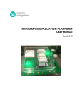
MAXREFDES24EVSYS User Manual
1 Introduction
The MAXREFDES24EVSYS design accelerator kit allows users to quickly demonstrate and evaluate the
functionality of Maxim Integrated’s 4-channel analog output (AO) reference design (MAXREFDES24) without
the need for a bench power supply, digital multimeter, or Xilinx development kit. The reference board connects
to a PC through an included USB-to-SPI adapter (USB2PMB1) that provides data communication to the board.
A universal power adaptor is included for providing 24V DC power.
To exercise the AO reference design, a USB-powered signal capture board (MAXADCLite2) utilizing one of
Maxim Integrated’s 12-bit analog-to-digital converters (ADCs) is also included. The simple tool provides two
inputs capable of measuring unipolar analog control signals up to 10V (or 20mA with selectable termination
resistor).
Windows®-based graphical user interfaces (GUIs) communicate with the boards for generating and capturing
various signal test patterns. An intuitive alarm interface is also provided for demonstrating the digital
diagnostics capabilities of the MAX15500 output conditioners.
1.1 Ordering Information
PART
MAXREFDES24EVSYS#
DESCRIPTION
Bundled kit for PC evaluation of MAXREFDES24
#Denotes a RoHS-compliant device that may include lead that is exempt under the RoHS requirements.
1.2 Package Contents
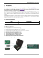
The MAXREFDES24EVSYS kit includes the following:
•
MAXREFDES24 reference design board (Pmod
•
Universal 24VDC power supply with international plugs and test clip adapter
•
USB2PMB1 USB-to-Pmod Type 2A adapter board
•
USB-powered MAXADCLite2 signal capture board
TM
compatible)
•
Two (2) USB type-A male to USB type-B mini cables
•
Two (2) wires with hook clips (1 red and 1 black)
•
USB flash drive with documentation and GUI applications
•
Quick Start Guide (print copy)
Rev 1
3