1
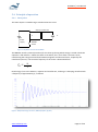
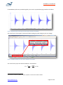
HFIT600A | User Manual 7 HF insulation breakdown – theory and detection 7.1 Thermal effects / dielectric dissipation factor () All insulating materials heat up when an ac voltage is applied. At very low frequencies, such as 50/60Hz mains, this effect is tiny and requires very high voltages to become significant. However at electrosurgery frequencies around 400kHz, the effect is significant at even at relatively low voltages, with some materials having observed temperatures exceeding 100°C well below 1000Vrms. The insulation under test can be modelled as an ideal capacitor in series with a resistor. The property of the material generally used is the “dissipation factor” or “loss tangent”, which needs to be measured around the frequency of interest. A dissipation factor of 1% effectively means that 1% of the impedance appears as resistive component, and 1% of the apparent power will end up as heat. For example, if the capacitance of a test sample is 100pF, has a dissipation factor = 2%, and is tested at 1000Vrms, 400kHz, the calculations are: C impedance = 1/(2π x 400k x 100p) = ~ 4000Ω Power (apparent) = 10002 x 2π x 400k x 100p = ~ 250VA Resistive component = 4000Ω x 2% = 80Ω Heat in test sample = 250VA x 2% = 5W Generally, the physical volume of the insulation in the test sample is small, so power of 5W can easily produce very high temperatures. However, the actual temperature will vary greatly depending on the set up and the test sample’s physical construction. If the insulation is tested in water, water will cool the insulation. If the test sample has a large metal surface it can also cool the insulation. Thick material can sometimes end up worse than thin materials, as the heat cannot escape from inside the insulation as easy. Different materials have different amounts of heating, for example Teflon has very low dissipation ( typically <0.1%), while PVC has relatively high dissipation (1-3%). The amount of heat produced is a function of the rms voltage squared, so a 10% increase in voltage can produce 21% more heat. The amount of heat is also a function of thickness squared (inverse), so a 10% reduction in thickness produces 21% more heat. As such, accurate control of the rms voltage is important for the test. Also, if the insulation thickness varies in real production, testing of multiple samples is reasonable. The HFIT has been tested with simulated high dissipation factor loads (100pF in series with 320Ω, = ~8%, around 10W resistive load at 1000Vrms, 300kHz). The output remained stable and was able to reach all specifications. A factor of = ~8% is expected to be well above all reasonable quality insulation at HF. In many cases, high temperatures in the order of 100°C can be reached but the insulation does not break down if this is below the thermal limits of the material. This is allowed in IEC 60601-2-2 (and www.whaleteq.com Page 21 of 26