1
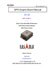
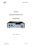
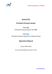
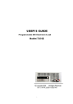
HFPA150 | User Manual WHALETEQ ESU Neutral Electrodes Impedance Tester Model: HFPA150 User Manual Version2014-10-30 Hardware Version1.3.x www.whaleteq.com HFPA150 | User Manual 1. Introduction HFPA150 is a unique tester specifically designed for the testing of neutral electrode (NE) impedance in electrosurgical system. The HFPA150 is built to satisfy the testing requirements for contact impedance test as stated in IEC60601-2-2:2009. According to IEC 60601-2-2:2009 clause 201.15.101.6, the impedance of the electrical contact between the surface of the NE application site and the NE cord connection shall be low enough to prevent a risk of patient burn due to ohmic heating during the passage of HF surgical current. It is evident that hazard of patient burn during the use of electrosurgical system is present. The main contribution to the risk of patient burn is caused by the high impedance of the NE application site and the NE cord connection. Thus, this safety test is especially important for the neutral electrode manufacturers. The HFPA150 generates specific NE impedance test signals per requirement of the IEC standard. The built-in generator is capable of generating signals with frequency ranging from 50 kHz to 5 MHz, producing current over 200 mArms, and sine wave with THD < 0.3%. The HFPA150 is built with high stability output, adjustable frequency and gain functions. In addition to neutral electrode test, it could also be used as a measurement tool for general purpose generator where the specifications are appropriate. Features: i. A sine wave generator: user may adjust the frequency and gain to meet the needs of high-power sine wave output. ii. Stable frequency output: equipped with DDS (direct digital synthesis) technology, a frequency synthesizer for generating arbitrary waveforms from a single, fixed-frequency reference clock. Together with an embedded DC fan for ventilation and control of the internal temperature, the HFPA150 is not susceptible to temperature fluctuation which facilitates great output stability. Compared to a conventional sine wave generator which creates waveforms based on the charging and discharging of the capacitor, the stability of waveforms is therefore determined by the capacity of the capacitor. However, the capacity change is proportional to the ambient temperature while inversely to the generated frequency. Thus, a common problem with the conventional sine wave generator occurs with the heat generated from prolong usage and resulted with the lower frequency generated. www.whaleteq.com Page 2 of 19 HFPA150 | User Manual iii. Compliance with IEC60601-2-2: 2009 testing requirements: the HFPA150 is designed according to the standard of the neutral electrode (Neutral Electrode, NE) contact impedance test. iv. Produce current over 200 mArms (~ 570 mApp), compliance with the standard requirement. v. With the amplified built-in sine wave generator, the output voltage can be up to 10 Vrms (at 50 Ω impedance). vi. Capability to measure to the upper limit of the contact impedance of the neutral electrode at 50 Ω. vii. Frequency is adjustable from 50 kHz to 5 MHz. Note: An oscilloscope shall be used with the HFPA150 to measure the output voltage and current. The HFPA150 is equipped with a built-in conversion circuit, so that no additional current probe is required to measure the current value. User may simply connect the "Current Monitor" port with an oscilloscope to obtain the current value. (For details, please refer to Chapter 6B, < How to monitor the HFPA150 output voltage and current>). www.whaleteq.com Page 3 of 19 HFPA150 | User Manual 2. Safety Summary Please review the following safety warnings to avoid injuries and prevent damage to this product or any related products. To avoid potential hazards, only use the product in accordance with this instruction. Only Whaleteq qualified professionals should repair/adjust the operation program. To avoid fire or personal injuries, only use the original factory-supplied power supply. The equipment shall be operated by a qualified electrical engineer or a professional with equivalent qualification and knowledge in the principle of high-frequency insulation and oscilloscope use. Please read this user manual carefully for the working principles and possible risks before first operating the HFPA150. If the power output is over 2 watts, pay special attention to the heat and power tolerance while connecting the load. Always use safe work practices when using electrical equipment to avoid the risk of electric shock and fire. www.whaleteq.com Page 4 of 19 HFPA150 | User Manual Main applications: IEC60601-2-2:2009 Measurement of neutral electrode contact impedance. Recommended test instruments: 201.15.101.1 General requirements for NEUTRAL ELECTRODES Not testing required 201.15.101.2 NE code attachment v 201.15.101.3 NE cord connector, no conductive parts on patient v v 201.15.101.5 NE thermal performance2 v v 201.15.101.7 NE adhesion v Use test finger 201.15.101.4 NE cord insulation 201.15.101.6 NE contact impedance Remark Digital Multimeter DC Power Supply Heat induction meter Oscilloscope HFPA150 201.15.101 Neutral Electrodes HFIT600A1 Testing of neutral electrode according to IEC 60601-2-2:2009 V v Refer to Note2 v Non-electrical test 201.15.101.8 NE shelf life Note 1: WhaleTeq HFIT600A, High-Frequency Insulation Tester: For insulation and current leakage test of cord and surgical instruments. Visit: http://www.whaleteq.com/products_detail/71 Note 2: No current probe is required when the HFIT600A is used as a generator. In the NE thermal performance test, IEC standard stated that the NE under test shall be applied on human skin, surrogate media or test devices with electrical and thermal equivalent properties. Since impedance varies with different contact surfaces, in some cases (especially with high impedance), the HFIT600A is not capable to provide current up to 770mArms (maximum output of HFIT600A is150W), and in such case, an ESU along with a current probe will be required to conduct the test. www.whaleteq.com Page 5 of 19 HFPA150 | User Manual 3. Specifications Parameters HFPA150 Specification Frequency range 50 kHz to 5 MHz Maximum voltage 11 Vrms (~31 Vpp), ≥ 50 Ω Maximum Current >200 mArms, ≤ 50 Ω Waveform Sine Frequency Response < ±0.8 dB, 50 Ω THD <0.3% (-50.4 dB), at 200 mArms, 50 Ω, 1 MHz Impedance <3.2Ω + j0.4 µH Auxiliary equipment for contact impedance test Oscilloscopes (Ch1 connects with voltage probe to measure voltage, Ch2 connects with HFPA150 current monitoring interface to measure the current value) Current Measurement Accuracy* < ±5% Frequency Range 50 kHz to 5 MHz Connector Type BNC General Power Source Power Adapter Input: 100 – 240 V, 50/60 Hz Output: 12 VDC / 2 A Environment 10 oC to 40 oC, 30% to 90% RH Dimensions / Weight 18X18X4.8 (cm, LxWxH) / 0.7 kg *Use with original factory-supplied connection cord (BNC-BNC) and test cords (BNC-Alligator). See Chapter 5 for cord specifications. www.whaleteq.com Page 6 of 19 HFPA150 | User Manual 4. Labels Figure 1. HFPA150 back panel Back panel labels – Figure 1. Item Label Name Description 1 DC IN 12V Power Interface 12 VDC power input connecting to the power supply 2 On/Off Power switch On/Off Switch www.whaleteq.com Page 7 of 19 HFPA150 | User Manual Figure 2. HFPA150 front panel Front panel labels – Figure 2. Item Label Name Description 1 Output Signal output port Signal output. BNC connector. 2 Frequency Frequency adjustment knob Turn clockwise to increase frequency and turn counter clockwise to decrease frequency 3 100KHz 100 kHz indicator (Green) Illuminates to indicate for 100 kHz selection. Frequency is adjusted to be 100 kHz per step. 4 10KHz 10 kHz indicator (Yellow) Illuminates to indicate for 10 kHz selection. Frequency is adjusted to be 10 kHz per step. 5 100K/10KHz Frequency 100 kHz/10 kHz Switch button Press for switch between 100 kHz and 10 kHz. 6 Gain Gain knob Turn clockwise to increase amplitude and turn counter clockwise to decrease amplitude *Read Chapter 6C <Gain Adjustment> before operation 7 Gain Indicator Gain indicator (Green) The flashing light indicates signal output. The light will be solid green when there is no signal www.whaleteq.com Page 8 of 19 HFPA150 | User Manual output or when the reset button is pressed. 8 9 Gain Reset Current Monitor Gain reset Press to reset gain to zero Current monitoring port Connect the oscilloscope with the original factory-supplied BNC cord to monitor the current value. (The oscilloscope shows 1 mV is equivalent to 1 mA of current flowing through the DUT.) www.whaleteq.com Page 9 of 19 HFPA150 | User Manual 5. Original factory-supplied connection cords HFPA150 is capable to measure the output current value through a current monitor port with direct connection to the oscilloscope using the BNC-BNC cord. This unique design saves cost and the need of an expensive current probe. A BNC-Alligator cord is supplied for the connection to the signal output port in order to pass the test signal to the connection points and metallic plate of NE. To control the accuracy of monitoring the current to ±5%, the HFPA150 measures the current by means of a 1 Ω shunt together with the frequency compensation circuit. According to IEC60601-2-2 clause 201.15.101.6, NE contact impedance test frequency shall range from 200 kHz to 5 MHz. As the frequency changes, the small capacitance of the test cord with the HFPA150 resistor results in noticeable RC effect, leading to significant deviation of frequency response. The original factory-supplied cords with the HFPA150 are designed to resolve the above described issues. It is strongly recommended to use the original factory-supplied cords for measurements. The specifications of the cord are as follows: a) BNC-BNC cord Exclusively designed for HFPA150 current monitoring, the BNC-BNC cord connects the current monitoring port with the oscilloscope. The indication of 1 mV is equivalent to 1 mA current flowing through the DUT. Figure 3. BNC-BNC cord www.whaleteq.com Page 10 of 19 HFPA150 | User Manual Length 50 cm Cord Capacitor 50 pF ± 5 pF Impedance 50 Ω Type of cord RG58U b) BNC-Alligator cord The BNC alligator clips on the short cord is specifically designed for NE tests. It connects the HFPA150 with the DUT. Each of the alligator clip connects the wire connection port of the DUT (neutral electrode) and the metallic plate/prosthesis Figure 4. BNC-Alligator cord Length 20 cm Cord Capacitor ≤20 pF Impedance 50 Ω Type of cord RG58U Note: When using the BNC-Alligator cord, avoid contacting the two alligator clips together. Contacting the two alligator clips under no-load condition can cause output short circuit, equipment damage, and possible risk of fire and electric shock. www.whaleteq.com Page 11 of 19 HFPA150 | User Manual 6. Instructions A. Power DC Power Port 1. Connect the power adapter (100 V – 240 V, 50/60 Hz) * Always use the original factory –supplied power supply. Powering up 1. Switch the HFPA150 on. 2. Upon powering on the HFPA150, the green “Gain Indicator” and the yellow “10KHz” indicators illuminate. Frequency initiates at 50 kHz with no voltage through “Output” port. B. How to monitor the HFPA150 output voltage and current HFPA150 measures the output voltage and current through two connecting ports of the oscilloscope: 1. Connect the original factory-supplied BNC-BNC cord* with the "Current Monitoring” port and oscilloscope CH2. 2. Connect the “Output” port with the BNC-Alligator cord. Connect the other end of this cord to the analytes (DUT) and voltage probes connect with the oscilloscope CH1 (as shown in Figure 5) 3. Power up the HFPA150, turn the "Gain" knob clockwise to read a 50 kHz signals from CH1/CH2. The HFPA150 is working properly when amplitude increases with gain increase. The 1 mVrms at CH2 is equivalent to 1 mArms www.whaleteq.com Page 12 of 19 HFPA150 | User Manual current. CH1 voltage and frequency indicates the output voltage and frequency. Figure 5. Test wiring diagram * To achieve HFPA150 current monitoring accuracy (<± 5%), use the original factory-supplied connection cords www.whaleteq.com Page 13 of 19 HFPA150 | User Manual C. Parameter adjustment Gain 1. “Gain” knob: use for gain output adjustment. Monitor the oscilloscope to adjust the desired voltage/current. Turing the knob clockwise to increase the gain; counter-clockwise to reduce the gain. 2. A flashing “Gain Indicator”: indicates signal being output. The light will be solid green when there is no signal output or the reset button is pressed. 3. “Gain Reset”: Press to reset gain to zero. For safety reason, always reset gain when replacing analytes. Notes: 1. While doing gain adjustment, always monitor the current/voltage by an oscilloscope. Overcurrent will activate the protection circuit. See Chapter 7 <Overcurrent protection> 2. When replacing the analyte, press "Gain Reset" to avoid hazard to operators or damage to HFPA150 unit due to sudden load reduction and current increase. 3. While turning the “Gain” knob to increase gain, the power output also increases accordingly. If the power output is over 2W, pay special attention to the heat and power tolerance while connecting the load. Always use safe work practices every time electrical equipment is used to avoid the risk of electric shock or fire. 4. While using the BNC-Alligator cord, avoid contacting the two alligator clips together. Contacting the two alligator clips under no-load condition can cause output short circuit, equipment damage, and possible risk of fire and electric shock. www.whaleteq.com Page 14 of 19 HFPA150 | User Manual Frequency 1. "Frequency" knob: use for frequency output adjustment. Monitor the oscilloscope to adjust the desired frequency. Turning the knob clockwise to increase the frequency; counter-clockwise to reduce frequency. 2. “100KHz” indicator: Illuminates to indicate for 100 kHz selection. Frequency is adjusted to be 100 kHz per step. 3. “10KHz” indicator: Illuminates to indicate for 10 kHz selection. Frequency is adjusted to be 10 kHz per step. 4. "100KHz/10KHz Frequency" switch button: Press for switch between 100 kHz and 10 kHz. www.whaleteq.com Page 15 of 19 HFPA150 | User Manual 7 . Overcurrent protection To ensure the safety operation and avoid the risk of damage to equipment due to improper use, the HFPA150 is built with a set of overcurrent protection circuit. When “Detected circuits” detects an overcurrent, it will target the “Power Amp (Turn Off)” to reduce immediately. In case the limit is reached, the “MCU” receives the signal and subsequently adjusts the “Variable Amp” of the gain value to “0”. Figure 6 below illustrates the principle of the protection circuit activation. Figure 6. Protective circuit block diagram Instant current rise will results in an event that the impedance of the analyte is very low or even short circuit. In such case, using firmware to control “MCU” and further adjusting the gain value is not going to be responsive enough. The protection circuit works in the way of turning on the hardware as soon as overcurrent is being detected so that the “Power Amp” is reduced immediately. At this point, waveforms will distort (Figure B) due to the current decrease. There could also be no waveforms (Figure C) when the “MCU” adjusts the “Variable Amp” to Low gain “0.” Both waveform distortion (Figure B) and no waveform (Figure C) indicate the protection circuit is activated. Readjust the gain value (increase or decrease) as needed. www.whaleteq.com Page 16 of 19 HFPA150 | User Manual Figure A: Normal waveforms on the oscilloscope display before protection circuit is activated. Figure B: Distorted waveforms after protection circuit shuts down the “Power Amp”. Figure C: No waveform displayed after “MCU” adjusts the “Variable Amp” to Low gain “0.” www.whaleteq.com Page 17 of 19 HFPA150 | User Manual 8. Test example Test of ESU Neutral Electrodes Impedance Test Refer to Figure 7 for HFPA150 connection for neutral electrode contact impedance test. 1. Connect the original factory-supplied BNC-Alligator cord from the "Output" port to the neutral electrode (NE) plates. Connect the red alligator clip to the NE connector and the black alligator clip to the adhesive metallic plate. 2. Connect the oscilloscope probe (CH1) to the same point as the red alligator clip on the NE connector, and connect the ground end of the probe to the adhesive metallic plate. 3. Connect the HFPA150 “Current Monitor” port and the oscilloscope CH2 using the original factory-supplied BNC-BNC cord. 4. Adjust HFPA150 "Gain" and "Frequency" to CH2 200 kHz, Vrms=200mVrms. (This indicates Irms=200mArms). 5. Measure Vrms voltage of CH1. Use the equation Z=V/I to get the contact impedance value. Note: Turning the “Gain” Knob clockwise will increase gain and output power accordingly. When the output voltage exceeded 10 Vrms while the output current does not reach 200mArms, this is an indication that the neutral contact impedance of tested negative plate is more than 50Ω. (IEC60601-2-2:2009 clause 201.15.101.6 stated that the neutral electrode impedance shall not exceed 50 Ω). Stop increasing the gain in such event and record the rms voltage and current. Calculate the contact impedance value for the neutral electrode. 6. Adjust the frequency to 500 kHz/1 MHz/2 MHz/5 MHz and repeat step 4 and 5. www.whaleteq.com Page 18 of 19 HFPA150 | User Manual Figure 7. HFPA150 connection for neutral electrode contact impedance test 9. Contact WhaleTeq Email: Address: Phone: Website: [email protected] 8F-3, No.106, Minquan W. Rd.,Taipei City 10361, Taiwan +886 2 25501239 www.whaleteq.com www.whaleteq.com Page 19 of 19