1
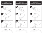
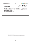
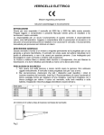
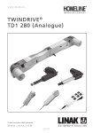
assembly manual
for GO2 WorkCenter
section one
workcenter assembly
eisys®/healthcare
2
rev.13 10.2011
TABLE OF CONTENTS
section one – workcenter assembly
Tools/Hardware....................... 4
Components............................ 5
Frame Layout.......................... 5
Feet Assembly......................... 6
Resetting Control Panel.......... 7
Gas Spring Preperation.......... 8
Attaching the Table Top........... 9
section two – accessory installation
Tools/Hardware.......................11
Preparing the Table Top.......... 12
Attaching Accessories
Mounting Rail Posts................16
Mounting Rail.......................... 16
Mounting Rail Accessories......17
Mounting Table Top.................17
Accessories
Mounting Table........................21`
Frame Accessories
Mounting CPU.........................22
UPS Holders
Rail Mounted Light.................. 24
Assembly
Contact Information.................27
and Assistance
eisys®/healthcare
3
rev.13 10.2011
TOOLS NEEDED FOR WORKCENTER ASSEMBLY
Phillips & flat head screwdriver
#1 Phillips Bit
Metric Allen wrenches 2-8mm (Long T-handle 4mm helpful)
Wrench or socket 7, 8mm
Torx head screwdriver T25
HARDWARE LIST FOR WORKCENTER ASSEMBLY
FRAME
Column Mounting Plate screw T25 20mm
(4 at each end of each column-already installed)
Table Top mounting Allen bolt 5mm (or 4mm) x 25mm
(8) - supplied
eisys®/healthcare
4
rev.13 10.2011
1. COMPONENTS
Box A
Box (A) Frame and optional accessories
Box B
Box (B) Table top, Support Structure,
Cable Outlets (3)
Unpack and layout all components from
box (A). All the fasteners are in individual
bags taped to the relative component.
• (A) Frame
• (B) (2) short feet, (2) long feet
Options:
• (C) Monitor rail
• (D) (2) monitor rail posts
• (E) Cable Tray with or without MBMOU
and power strip
• (F) Accessory Boxes
A
B
B
D
E
C
2. FRAME LAYOUT
• Lay frame upside down. The control
panel cable always exits the
cross rail at the back of the
frame.
Front
• Motor housing is flush with the
back side of frame. The angled
side is the front of the frame.
Back
• The short legs always attach at
back of frame. The long legs
always attach at front of frame.
eisys®/healthcare
5
rev.13 10.2011
3. FEET ASSEMBLY
• Using 4mm long T-handle Allen wrench, loosen but do
not remove completely, Allen bolts on foot binding clamp.
(pic. 1.)
• Align foot and binding clamp in grooves of leg (pic. 2)
and slide down to the numbered markings. (pic. 2a)
• (pic. 2a) The top of the foot (when frame is turned upright)
should stop on the line between zero (0) and one (1). This
sets the minimum table height to 68cm (26.75”) and will allow for adequate bottom of frame clearance for most flooring surfaces including carpet.
pic. 1
Note: If customer requests a change in height,
you may line up the feet on higher numbers if
you want the minimum table height to be greater
than 68cm. (26.75”)
Each mark represents one (1) cm.
Total range is 10 cm or 4”.
Be careful to line up all four feet to the same
number as to make sure the workcenter
is level. (pic. 4)
pic. 2a
pic. 2
pic. 3
pic. 4
eisys®/healthcare
6
rev.13 10.2011
4. RESETTING THE CONTROL PANEL
• Keeping frame upside down, plug desk in. You will
see blinking zeros on the control panel. (pic. 1)
• To reset the control panel, press and hold the
down arrow button until column reaches its lowest
position. Continue to press the down arrow until
diplay reads 067 or 068. The workcenter controls
are now reset.
NOTE:You cannot raise the table until you reset
the column at its lowest position.
pic. 1
YOU ARE Now READY TO raise the table
assembly Using the up arrow (^).
pic. 2
5. GAS SPRING PREPARATIONS
(not appliciable if factory installed)
• Extend the leg columns completely by pressing
and holding the “up” arrow until top reaches 120cm
shown on display. (pic. 3)
• Remove the cover (stabilizing plate) on the foot
side of the column by loosening the four (4) counter sunk screws. (pic. 4)
pic. 3
THE COLUMNS HAVE TO BE COMPLETELY
EXTENDED BEFORE INSTALLING GAS
SPRINGS BECAUSE OF THE RISK OF INJURY
BY THE PRESSURIZED GAS!
pic. 4
eisys®/healthcare
7
rev.13 10.2011
6. INSTALLATION OF GAS SPRINGS (not appliciable if factory installed)
pic. 2
pic. 1
• Align the stabilizing plate with the piston rod of the gas spring side of the
plate with countersunk holes facing away from spring.. Plate has to be
rotated clockwise on the piston rod to secure. (pic.1)
• Center gas spring with stabilizing plate into column and align plate
with (4) screw holes.
• Mount the plate (pic.2) using the four (4) Torx head countersunk screws and
Torx25 tip. Tighten screws evenly to compress cylinder until plate is flush with
leg column.
Note: Tighten screws slowly in an alternate pattern making sure plate
compresses evenly.
eisys®/healthcare
8
rev.13 10.2011
7. ATTACHING TABLE TOP
NOTE: IF THE MODEL NUMBER ENDS IN Z OR ZM: AFTER THE GAS SPRINGS ARE
INSTALLED, THE FRAME HAS TO HAVE APPROXIMATELY 88 LBS OF WEIGHT ADDED
WHILE RAISING OR LOWERING THE TABLE ASSEMBLY.
(TO ADD WEIGHT, LEAN ON FRAME, EXERTING APPROXIMATELY 88 LBS OF PRESSURE
WHILE PRESSING AND HOLDING THE UP OR DOWN ARROW.)
CAUTION: FAILURE TO DO THIS MAY DAMAGE MOTOR OR GEARS.
pic. 1
pic. 2
pic. 3
pic. 4
• Align frame with top support structure and attach columns to top (pic 2 with pic 3)
with supplied (8) #4 Allen head bolts- 4 per column.
Note: When table top and columns are aligned, the two plates
will be flush.
*Jobsite Conditions:
A. If you are assembling the workcenter in the room where it will reside, you
can assemble the entire unit upside down and then place right side up.
B. If you are assembling the workcenter outside of the room where
it will reside, the control panel cannot be attached to the top until the table top
and leg assembly are placed in the final room location
eisys®/healthcare
9
rev.13 10.2011
section two
accessory installation
eisys®/healthcare
10
rev.13 10.2011
TOOLS NEEDED FOR ACCESSORY INSTALLATION
• Phillips head screwdriver
• #1 Phillips Bit
• Metric Allen wrenches 2-8mm (Long T-handle 4mm helpful)
• Wrench or socket 7, 8mm
Hardware List- section two
Rail Post mounting Allen bolt 6mm x 50mm
(4) - supplied
Rail Post mounting Allen set screw
(4) - supplied/installed
Phillips 3/4” wood screw used for (Light Ballast) (4),
-unless Generation II Cable Tray is used.
Cup Holder (3)
Phillips 1 1/2” wood screw Light Control switch box(2)
Wire management clips (for Control Panel Cable)
eisys®/healthcare
11
rev.13 10.2011
1. PREPARING TABLE TOP
6F
6D
6B
6A Multi-Outlet Strip/Cable Tray
Generation II
6E
6C
6B
Control Panel
6C
Pencil Tray
6D
Cup Holder
6E
User’s Manual
6F
Wire Management
6A
pic. 1
• Pic. 1 shows position of all standard, optional accessories attached to the bottom of the
table top and of user’s manual placement location.
• Open Box B (table top) with finished top facing down, exactly as shown in
pic.1; this makes for easier installation of accessories and frame (space permitting).
Note: Pre-tapped holes are used to aid in accessory placement on underside of top.
1A - Multi-Outlet Strips & MBMO-U
MBMOU is an adapter plate used to mount power strips to Generation I Cable Tray. The 2 Duplex and 4 Duplex can also be mounted to the
Generation II Cable Tray using the MBMOU mounted to the slotted door of the cable tray.
• Mount in cable tray as seen in pic. 2 and in Generation II as seen in pic. 2A
Use plastic thumbscrews to secure. (pic. 2B)
pic. 2B
2-Duplex
4-Duplex
pic. 2A
pic. 2A
• Mount 6-Duplex Multi-Outlet strip in Generation II cable tray as seen in pic. 3.
Use screws to secure. (pic. 3B)
pic. 3
6-Duplex
with Generation II Cable Tray
no MBMO-U required
eisys®/healthcare
pic. 3A
12
rev.13 10.2011
1A-1 - Cable Tray- Generation I
pic. 3
pic. 4
pic. 5
• Position cable tray as seen in pic. 3 and pop tray into place by slide lip of cable
tray under triangular tube.
• Use mounting brackets (2) (Pic. 4) and nut/bolts to secure tray to triangular tube.
(Pic. 5)
1A-2 - Cable Tray- Generation II
pic. 6
pic. 7
pic. 8
• Center cable tray over triangular tubes with the hinged door facing toward the
rear of desktop. (Pic 6)
• Center cable tray left and right of desktop. (Pic 7)
• Attach using the 3/4” wood screws. (Pic 8)
eisys®/healthcare
13
rev.13 10.2011
1. PREPARING TABLE TOP cont.
1B - Preparation for the Control Panel
Note: The control panel cannot be installed
or secured to the top until top is mounted to
the frame and workcenter is in its final
location. Be sure control panel cable comes
from behind and over cross rail.
• Locate the pre-marked holes for the control
panel mounting plate. Pre-drilled holes should
allow this.
• Position control panel mounting plate at premarked holes (pic. 6). This bracket allows the
control panel to slide approx. one inch front to
back
pic. 6
• Place control panel on top of mounting slide
plate and position control panel so that when
slid to front of plate, the panel is flush with front
edge of table top.
• Fasten with supplied (3) Phillips head screws
using #1 Phillips bit ONLY.
pic. 7
Note: Caution should be used not to strip
the #1 Phillips head screw.
CAUTION: DO NOT OVER TIGHTEN. CONTROL PANEL WILL NOT SLIDE.
1C- Pencil Tray
• Use the 2 holes located on front edge of top, the opposite side from the control panel.
see Pic 8
CAUTION IS NEEDED AS TO NOT OVER TIGHTEN SCREWS. OVERTIGHTENING
SCREWS MAY CAUSE THEM TO PUNCTURE LAMINATE ON DESK SURFACE
pic. 8
eisys®/healthcare
14
rev.13 10.2011
1. PREPARING TABLE TOP cont.
1D - Cup Holder
• Attach cup holder at pre-tapped holes on the under side of top, left or right corner, with supplied
(3)-3/4” Phillips head wood screws.
Note: Preferable location is the opposite side
of the CPU placement.
pic. 10
1F- User’s Manual
• User manual is located in the Frame Box. (Pic 11)
• Remove film backing from packet and apply packet
on underside of table where indicated in pic.12.
pic. 11
pic. 12
eisys®/healthcare
15
rev.13 10.2011
2. MOUNTING RAIL POSTS
CAUTION: Rail and Rail Accessories can not be installed until table top is attached
to leg assembly and placed upright.
• Post should be mounted on table top with 4 supplied 6mm allen head bolts.
• Place one full washer on table top surface and the second half washer on the underside
of the table top. (Pic 2 and Pic 3)
Note: DO NOT tighten posts completely until rail is positioned on posts (step 2).
pic. 1
pic. 2
pic. 3
3. MOUNTING RAIL
• Pic. 1 shows position of installed rail and posts.
NOTE: Rail may be mounted in front or behind
support posts.
CAUTION: Loosen 2.5 mm allen screws (A-pic 2)
and the 2 mm allen screw (B-pic 2) so that
they are recessed from the inside of the rail collar
or damage to post could occur.
pic. 1
• Slide rail down evenly over rail posts so that the
bottom of rail collar is even with the 2nd to last ring at
the bottom of post, approximately 10cm from work top.
Note: The rail height is determined by the size and style of
monitors. A good starting position is to place the collar at the
second ring from the bottom of the rail posts, approximately
10cm from the work top. It is also important to position the
rail collar on one of the post rings so the set screw A in
Pic 3 will fully tighten on the post.
pic. 2
B
A
• Tighten set screws carefully, not to over tighten.
• Once rail is positioned on post, finish tightening the bolts
securely on the post under the top (step 1).
pic. 3
eisys®/healthcare
16
rev.13 10.2011
4. MOUNTING RAIL ACCESSORIES
NOTE: Pic 1 shows how the accessory
arms should be spaced equally across
rail.
pic. 1
A. Advanced Height
Adjustable Arm
model # 3500250/450/800-RF
B. Manual
LCD holder
C. Phone Post
D. WLTC Indirect Light
TSA-RF
See Section 7
model # LCD-QRE-RF
4A. Mounting Advanced Height Adjustable Arm
pic. 1A
pic. 1B
pic. 2
pic. 3
pic. 4
• Place accessory on rail in approximate final location. Secure “V” clamp with 2, #4 Allen
head bolts. (pic.1A- in front; 1B in back)
• Attach 100mm VESA plate to monitor using same 4 screws supplied with monitor or
the 4 longer BLACK screws supplied with each Advance Height Adjustable Arm (pic. 2)
• The Advanced Height Adjustable Arm will require calibrating after mounting on the rail.
Follow the instructions on the next two pages to calibrate each arm.
eisys®/healthcare
17
rev.13 10.2011
4A-1. Advanced Height Adjustable Arm (Model 6654-parts list)
A
B
C
H
Monitor Tilter — 1
#8013
75mm
VESA Adapter Plate — 1
#7VESA75
100mm
VESA Adapter Plate — 1
#7VESA100
Mount Column — 1
#401328
I
3/8-16 Nylon Stop Nut — 1
#701418
J
3/8-16 x 7/8” (22.225mm)
Button Socket Cap Screw — 1
#701122
H
D
10-32 x 3/8” (9.525mm)
Phillips Flat Head Screw — 4
#701164
7/32” (5.563mm) Allen Wrench — 1
#701127
I
E
F
G
eisys®/healthcare
M4-12
Phillips Pan Head Screw — 4
#702096
3/32” (2.388mm) Allen Wrench — 1
#700146
J
Tilter Washer — 1
#704197
Cable Cap — 1
#102043-9.5A
10-31 x 3/8” (9.525mm)
Phillips Pan Head Screw — 1
#704197
18
rev.13 10.2011
4A-2. Calibrating the Advanced Height Adjustable Arm
Pic. 1
Pic. 3
Pic. 2
Pic. 4
• Step 1- Insert the end of the adjustment arm into Mounting Cup (part H)- Pic.1
• Step 2- Determine VESA Plate size prior to assembly. The VESA plate size is determined
by the mounting hole pattern on the rear of the monitor. Standard sizes are 100mm
square and 200mm square. Attach correct VESA Plate to Monitor Tilter (part A) with
the 4 10-32 x 3/8” (9.525mm) Phillips Flat Head Screws (part D)- Pic.2
(note- VESA plate in box does not have “B” or “C” designation on plate).
• Step 3- Attach the VESA Plate and Monitor Tilter to the monitor using 4 M4-12 Phillips Pan
Head Screws (part E)- Pic.3
• Step 4- Mount the Tilter and monitor into the top section of the arm.
Insert 10-32 x 3/8” (9.525mm) Phillips Pan Head Screw (part G)
and Tilter Washer (part F) in bottom of arm. Pic.4
(note- This is a security measure to prevent the monitor from being easily lifted off the arm.)
Pic. 5
Pic. 7
Pic. 6
Pic. 8
Pic. 9
• Step 5- Using supplied large Allen Wrench (part H) adjust tension on tilter to prevent monitor from dropping down or being to stiff to adjust. Pic.5
• Step 6- Using supplied large Allen Wrench (part H) adjust tension of arm. Increase (counter clockwise) or decrease (clockwise) tension as necessary and as dictated by weight of the monitor. Monitor and arm must be parallel to desk surface when calibrating arm. Pic.6
• Step 7- Adjust set screws at indicated locations to increase (clockwise) or decrease (counter clockwise) friction/tension for horizontal movement. The tension is generally set at the factory but over time may need to be adjusted. Pic.7
• Step 8- Insert monitor cable into two cable retainers and place Cable Cap (part J)- Pic.8
• Pic. 9- Calibrated monitor and height adjustable arm with cable in place.
eisys®/healthcare
19
rev.13 10.2011
4B. Mounting Manual Height Adjustable Arm
pic. 2
pic. 1
pic. 3
• Place accessory on rail in approximate final location. Once in final location
completely secure by securing “V” clamp with 2- #4 Allen head bolts.
• Attach 100mm VESA plate to monitor using screws supplied with monitor.
(pic. 2)
• LCD Holder quick release plate:
Slide monitor with plate into quick release receiver on the end of the monitor
arm. When firmly seated, the release arm on the VESA will lock into place
into the receiver. (Pic 3) (shown without monitor)
4C. Mounting Third Rail Support Post
• Place accessory on rail in approximate final location. Mark screw locations. (pic 1)
• Drill holes in desktop for each screw. (pic 2)
• Attach post with supplied #4 Allen Bolts (pic 3) and half washer on bottom (pic 4)
pic. 1
eisys®/healthcare
pic. 2
pic. 3
20
pic. 4
rev.13 10.2011
5. MOUNTING TABLE TOP ACCESSORIES
pic 1
pic 1A
pic 1b
pic 1C*
pic 1D
• Remove organizational hole cover. (pic 1)
1A - Remove cap & sleeve of org. hole. Position Desk Fixing Post w/ full
washer over org. hole. Insert bolt and small washer from under desk into
top with 300 mm post.
Appllicable with:
1B - Telephone Post Holder
1C- ßPaper Tray *Note: Org sleeve does not need to be removed
1D - LCD Arm - Manual Height Adjustment (LCD-QRE-DF)
INSTALLATION NOTE: Paper tray and Advanced LCD Height
Adjustable Arm can also be mounted to the desk top with optional
desk clamp.
NOTE: Step by step installation of triple paper tray in box. Desk Edge
Clamp not applicable when using org. holes.
6. MOUNTING POWER DOME
• Remove gromet hole cover.
• Insert wires of power dome through grommet hole (pic 1)
• Slide both halves together and place in grommet hole until
flush with desk top (pic 2)
pic 1
pic 2
eisys®/healthcare
21
rev.13 10.2011
7. CPU/LINE CONDITIONER INSTALLATION
• The GMCZ-6 comes with one connecting column and
one Support Plate for complete set up. (pic.1)
• 1. Determine the width of your CPU case. Loosen the two black
thumb screws on the side to extend the standard support platebut do not extend beyond the thumb screws. If the CPU is wider
than 5 1/4” then you will need to add the extensions that come
stored under the support bracket. This will give you a maximum
width of 11”. (pic 2)
To add the extensions remove from below storage area and
remove the factory installed outside support plate and turn to the
underside. Remove the #2 Allen head set screws with the
supplied Allen wrench. Insert the smaller end of the extensions,
hole for the set screw facing down, into the standard tubes.
Replace the set screws, insert the end caps from the accessory
pack and replace the support bracket. Adjust to width of CPU
and tighten thumb screws. (pic 3)
pic 1
• 2. Mounting the GMCZ-6 on the workcenter leg.(pic 4)
This can be mounted to the outside of either leg on the workcenter, preferably, out of foot area. If mounted inside, then the
maximum height of the CPU case cannot exceed 20 3/4” due to
the crossbar of the desk frame. Once this is determined, use
the supplied #4 Allen wrench to tighten the clamp to the leg
profile of the leg at the highest point on the leg.
• 3. An additional Support Bracket (pic 5) can be ordered to stack
multiple or a mix of CPUs and UPSs. Measure the height
of the piece that will sit in the bottom support to determine
where the height of the additional support will be located.
pic 2
pic 3
• 4. The Accessory Pack (pic 3) also contains rubber leveling
bumpers. Normally, 3 large ones spaced evenly on the outside
support ledge will adjust the CPU to level. (pic 4a)
pic 4
pic 4a
eisys /healthcare
®
22
pic 5
rev.13 10.2011
7.1 GMZC6 SPE INSTALLATION
• After assembly of the GMZC6, if necessary install the GMCZ6 SPE accessory.
(2) spacers
pic 1
pic 2
pic 3
pic 4
• Remove SPE accessory from box including bag with (2) spacers as shown (pic. 1)
NOTE: When mounting GMZC6 IN-BOARD in conjunction withe the NEW eisys
HINGED CABLE TRAY, the SPE accessory MUST be installed to protect the CPU
from cable tray collision when loweing the desk.
• Install SPE as shown, once you have set the proper width of the SP for your
particular CPU tower (pic. 2)
NOTE: The SPE slides under the SP rear rod and over the front rod.
• Next select the appropriate spacer to allow secure tightening of the SPE to
the SP rear extension rod (pic. 3)
• Align and finger tighten knurled screw with spacer. After final placement
of CPU in holder, finish tightening both knurled screws to their final secure
position (pic. 4)
• Finished product should be as shown (pic. 5)
NOTE: opposite side installation is identical.
pic 5
eisys®/healthcare
23
rev.13 10.2011
8. ASSEMBLY OF RAIL MOUNTED LIGHT- WLTC
Shown from front with shield rotated to
aim light on wall. Shield may be rotated
as desired to aim light in any direction.
Shown from back with shield removed.
TOOLS NEEDED FOR ASSEMBLY
Phillips head screwdriver
Allen wrench 5 mm
8.1 COMPONETS
B
C
B-1
E
E
A
F
D
(A) Ballast Housing w/ ballast (4- 3/4” Phillips Head wood screws)
(B) Light shield (B-1) Optional Blue Lens
(C) Flourescent lamp & cable
(D.1) Desk mounted switch box (2- 13/4” Phillips Head wood screws)
(D.2) Switch and cable
(E) Light posts (2) w/ clamps (4- #5 Allen Head screws)
(F) Power cable
(G) Black Nylon Knurled Screws for Light Shield Tension (2) (not pictured)
eisys®/healthcare
24
rev.13 10.2011
8.2 Position lamp in post ends
• Pic.1 - Insert lamp ends into posts until seated.
• Pic.2 - Shows lamp correctly seated.
pic. 1
pic. 2
8.3 Attach support posts to rail
• Attach light posts using the bottom clamps
and Allen bolts finger tight.
• Feed lamp power cord through rear slot
in clamp. Standing behind the desk, the cord
should come through the left post.
Mount swivel clamps so that posts can be mounted
in any location on a corner desk with a curved
monitor rail.
Note: Light post should be centered and
vertically straight.
eisys®/healthcare
25
pic. 1
rev.13 10.2011
8.4 Mounting the ballast housing
• Desktop Mounting:
Use the supplied 4 wood screws.
Locate the 4 predrilled holes, centered,
just forward of the rear triangular tube. (Pic 1)
Attach ballast here.
• Cable Tray Mounting:
(for Generation II Cable Trays only)
Use the supplied 4 bolts and thumbscrews.
Insert in the 4 holes located in
the bottom of the cable tray. Tighten.
(Pic 2)
pic. 1
pic. 2
8.5 Attach power switch to desktop
• Locate the two pre-tapped holes under
desk top and to the right of control panel.
• Attach switch box to bottom of desktop
with two (2) 1 3/4” wood screws provided.
(Pic 1) Switch box should be flush with
front edge of top.
• Manage wires with provided wire clips.
eisys®/healthcare
pic. 1
26
rev.13 10.2011
Heavy Duty
Height Adjustable Arm
with 3rd Post
Installation Instructions
Heavy Duty Height Adjustable Arm with 3rd Support Post(28-EI-RSRC)
Notice:
Due to the weight of Diagnostic Monitors, specific heavy
duty tilter/vesa plate, arm and mounting cup must be used for
this equipment. In addition, a specially designed support post
(that correctly accommodates mounting of the heavy duty cup/arm
assembly) is also required and must be in place directly beneath
the monitor/arm assembly. The instructions below present the
specific parts and steps required to mount a larger scale Diagnostic
Monitor including instructions for converting an existing support
post (part# 28-EI-3-RSRC) that might be used as part of the
installation.
Note: It
is critical and a requirement that any diagnostic monitor in
excess of 35 pounds be mounted per these instructions.
eisys/healthcare, inc.
2
1. Parts List
28-EI-3-RSRC (either previously purchased
or included with this order)
Height Adjustable Arm with Tilter
Height Adjustable Arm Mounting Cup
Heavy duty top portion of the rail clamp
(2) of the M5-0.8X50 DIN 12.9 hardened steel bolts
for attaching clamp to the rail
(1) #8 metric 1.25x30mm hardened steel
countersunk head screw w/12.9 rating
eisys/healthcare, inc.
3
2. ASSEMBLY
1.If you currently have a 28-EI-3-RSRC, remove the two silver screws and top portion
of the normal rail clamp. This top portion of the clamp should have two screw holes
that ARE NOT recessed and NO center threaded hole. Set aside this top piece and
the two silver screws
2. Replace the top portion of the clamp with the HD portion using the (2) #4 metric Allen
head M5-0.8X50 DIN 12.9 hardened steel bolts in the recessed holes on top of the
new HD clamp.
3. Using (1) #8 metric 1.25x30mm hardened steel countersunk head screw, attach the cup portion of
the Height Adjustable Arm with a 3/8” Allen wrench to the top clamp. Be sure to position the
cup recess over the small steel nipple. Tighten securely to a snug fit.
Caution: Do not over tighten
eisys/healthcare, inc.
4
2. ASSEMBLY (cont.)
4. Insert the bottom portion of the Height Adjustable Arm into the cup.
5. Attach the provided 100 X 200 vesa plate to the back of the monitor. Use the factory
screws when possible. Note: some monitor models may require the back housing to be
removed to accommodate the vesa plate (particularly the Barco 6MP Niofusion)
6. The tilter portion of the arm will fit into the top hole of the Height Adjustable Arm. To
adjust the tilter use the supplied Allen wrench to tighten or loosen the tilter mechanism
for the desired tilt angle of the monitor.
eisys/healthcare, inc.
5
2. ASSEMBLY (cont.)
7. To calibrate the arm’s tension so the monitor will stay in place once positioned, extend
the monitor arm fully and position both joints parallel to the desk top. Use the supplied
Allen wrench and insert where indicated (with the red arrow). Turn the Allen wrench
clockwise to loosen the tension and counterclockwise to tighten the tension. The arm
is calibrated when the monitor stays at the level that the user positions it and does not
‘drift’ when released.
For troubleshooting or technical support please call
Tim House at 205-937-0911
eisys/healthcare, inc.
6
Contacts:
General Manager — Dick Gardner p 205.329.7053
[email protected]
Technical Assistance — Paul Allen
p 205.329.7055
[email protected]
forward thinking solutions >healthcare >education >office
p. 8 8 8 . 9 4 1 . 1 9 4 2
f. 2 0 5 . 9 4 1 . 1 7 8 1
1 1 2
2 8 th
eisys/healthcare, inc.
S t r e e t
S o u t h
i nfo @ e i sy s-i nc. co m
w w w. e i sy s-i nc. co m
B i r m i n g h a m
7
A l a b a m a
3 5 2 3 3