1
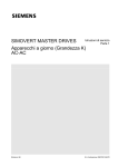
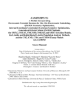
GreenArrays ® AN016 Incremental PID Controller for a Brushed DC Motor Application Note AN016 Revised 11/11/14 Incremental PID Controller for a Brushed DC Motor This paper describes how to control speed of a brushed DC motor equipped with an optical encoder using a PID controller in a closed loop system. The theory of regulation is well described in literature. Here we demonstrate suitability of GA144 chip for such a task in a practical application. The text also gives different examples of programming techniques and problem solutions such as double-precision and fractional arithmetic, custom Ganglion messaging and digital signal filtering. The work described herein is that of Daniel Kalný. Related Documents AN011: AN010: DB004: DB006: Ganglia Mark 1 Snorkel Mark 1 arrayForth® User's Manual polyFORTH® Supplement for G144A12 Contents 1. Introduction ............................................................................................ 2 2. arrayForth Implementation ..................................................................... 3 2.1 2.2 2.3 2.4 Edge Detection and Exponential Moving Average Filter ................................................... 3 PWM Generator, Timer and Data Relay ........................................................................... 4 PID Controller and Interface to polyFORTH ....................................................................... 5 Odometer ......................................................................................................................... 6 3. polyFORTH Implementation .................................................................... 6 4. Application ............................................................................................. 8 4.1 4.2 Experimental Setup .......................................................................................................... 8 PID Controller Performance .............................................................................................. 9 5. Conclusion ............................................................................................ 12 6. References ............................................................................................ 12 AN016 Incremental PID Controller for a Brushed DC Motor 1. Introduction Speed of a brushed DC motor can easily be controlled with a PWM generator. Changing the duty cycle of the PWM generator translates into a voltage change on the motor winding and consequently into motor rotational speed. A signal from an optical encoder attached to the motor shaft in the form of pulses can be used as feedback. It is either possible to count the number of pulses in a fixed time period or to measure the length of period between two consecutive pulses. The first approach is more suitable for slower controllers; the higher the number of pulses the higher the speed of the motor. The second approach is better suited for systems with fast controllers; the longer the interval between two pulses the slower the motor speed. There must however be an upper limit for the timer used for interval measurement as zero speed would correspond to infinite time between encoder pulses. If a closed loop system is desired a controller capable of setting the PWM duty cycle based on the feedback from the encoder must be used. Probably the most used controller in the field of industrial regulation is a so called proportional-integral-derivative (PID) controller. [1] The principle of the PID controller is shown in the following scheme. The controller calculates an error e(t) at time t as a difference between the desired setpoint w(t) of the controlled process (e.g. speed) and the measured process variable y(t) according to the expression: P - 𝑒(𝑡) = 𝑤(𝑡) − 𝑦(𝑡) + I e(t) 𝐾𝑃 𝑒(𝑡) 𝑡 𝐾𝐼 0 + 𝑒(𝜏)𝑑𝜏 D 𝑡 𝑢(𝑡) = 𝐾P 𝑒(𝑡) + 𝐾I ∫ 𝑒(𝜏)𝑑𝜏 + 𝐾D 0 u(t) process y(t) + w(t) The PID controller then calculates the control function u(t) by summing up the proportional, integral and derivative terms: + 𝐾𝐷 𝑑 𝑑𝑡 𝑒(𝑡) 𝑑 𝑒(𝑡) 𝑑𝑡 where KP, KI and KD are adjustable parameters corresponding to proportional, integral and derivative terms, respectively. For a discrete system, where measurement of the process variable is taken at evenly spaced time intervals T, the PID equation can be replaced by an equation: 𝑘 𝑢(𝑘) = 𝐾P 𝑒(𝑘) + 𝐾I ∑ 𝑒(𝑖) + 𝐾D (𝑒(𝑘) − 𝑒(𝑘 − 1)) 𝑖=0 where k is the k-th interval T. In this equation the integral term is replaced by a summation and the derivative term is replaced by a difference between the e(k), the error at interval k and e(k-1), the error at the preceding interval k-1. The PID controller described above is a positional type of controller. For motor control an incremental (or velocity) PID controller is more suitable. The incremental controller does not calculate the current value of u(k); instead its increment u(k) with respect to the last value is calculated. Thus, the incremental PID controller is defined as: ∆𝑢(𝑘) = 𝑢(𝑘) − 𝑢(𝑘 − 1) = 𝑞0 𝑒(𝑘) + 𝑞1 𝑒(𝑘 − 1) + 𝑞2 𝑒(𝑘 − 2) The parameters q0, q1, and q2 are given according to the following expressions: 𝑞0 = 𝐾P + 𝐾I + 𝐾D 𝑞1 = −𝐾𝑃 − 2𝐾D 𝑞2 = 𝐾D In order to implement the incremental PID controller, it is sufficient to keep in memory the three most recent errors and the accumulated control variable u. The calculation of the increment u(k) is achieved with three multiplications and summation of the results. 2 Copyright© 2010-2013 GreenArrays, Inc. 11/11/14 AN016 Incremental PID Controller for a Brushed DC Motor For the purpose of this application note, the discrete incremental PID algorithm has been modified. First, the error is not calculated at evenly spaced time intervals. Instead, the distance between encoder wheel slits is constant and the time component is provided by a free running counter. As a consequence, the error is calculated according to the expression: 𝑒(𝑘) = 𝑦(𝑘) − 𝑤(𝑘) where y(k) is the number of cycles the timer has counted from the last encoder pulse to the current pulse and w(k) is the desired timer count set by a high level control program. The terms are in the inverse order so the error e(k) is positive when the motor speed is lower than desired (timer count is higher than required) and therefore the increment of the control variable u(k) is also positive (meaning that the PWM duty cycle should be higher and the motor should accelerate). Similarly, the error is negative if the speed of the motor is higher than desired. This allows us to have the controller parameters KP, KI and KD positive. Consequently, the parameters q0 and q2 are positive and q1 negative. In order to avoid having q1 negative, which complicates multiplications in F18 code, the algorithm is modified in such a way as to negate e(k-1) before multiplying it with positive q1. 2. arrayForth Implementation The DC motor controller is implemented in three nodes. The layout is shown in this figure. The flow of data is symbolized with arrows. The green arrow represents a count from the free running timer, the yellow arrows correspond to a value of the count filtered with an EMA filter, and the purple one is a duty cycle for PWM generator calculated by the PID controller. Blue arrows symbolize communication with the polyFORTH virtual machine using Ganglion messages. The fourth node 216 could be optionally used for an odometer (see section 2.4). It receives a signal from 217 with each falling edge of the encoder. The number of such signals is counted and the current count can be read with polyFORTH high level code. 316 317 PID PWM comm 216 217 ODO edge detection EMA motor driver encoder The code is stored in blocks 856 to 862 of the arrayForth system. The main load block and boot descriptors block are listed below. The following section reveals details of the arrayForth code. 850 list main load, ema 856 load, pwm 858 load, pid 860 load, odo 862 load 852 list boot descriptors, ema 217 +node 217 ..down /a 21 /p, pwm 317 +node 317 ..10 /p, pid 316 +node 316 odo 216 +node 216 /ram 1CCCD 1FFFF 2 /stack, /ram 0 0 2 /stack io /b, /ram 0 0 2 /stack 2E /p, /ram 1F5 /a io /b 7 /p, 2.1 Edge Detection and Exponential Moving Average Filter The output of the optical encoder is connected to the pin 217.17 which is configured as a high impedance input. Out of reset the code starts at go. The WD bit of the IO register is set high in edge and the node is suspended until there is a high to low transition on pin 17. Following the falling edge ema is called. There are always two numbers on the stack; the last output from the filter s on top and a weighing coefficient w below it. The coefficient w is represented as a 17-bit fractional number in a range from 0 to 1 exclusive. The MSB is effectively a sign bit and should always be zero (the coefficient is always a positive number). Out of reset these values are set to x1FFFF (corresponding to zero speed) and x1CCCD (corresponding to 0.9), respectively. The filter first calculates the contribution from the last output as s × w . Then the down port is read (the current count from timer in node 317). The value read is multiplied by (1 - w) and the sum of the two values makes the new output value s which is duplicated and written back to the down port. If the odometer is implemented then odo is called to send a signal to 216. The signal is a dummy word which has no meaning and node 216 ignores it altogether. In case no odometer is implemented the highlighted code in block 856 should be removed. Copyright© 2010-2011 GreenArrays, Inc. 11/11/14 3 AN016 Incremental PID Controller for a Brushed DC Motor Returning back to edge the WD bit is set low and the node suspends until a low to high transition on pin 17. The code in edge is repeated in an infinite loop go. Most of the time the node is in the suspended mode running only when triggered by a transition of the encoder signal. edge detector, ema filter, , 1+ increment *.r fractional multiplication with rounding, ..b - unsigned integer 0 to 1FFFF, ..a - signed positive 17-bit fraction, ....0.x xxxx xxxx xxxx xxxx, ..rounding up if bit a17 high after, ..multiplication ema read count c from down port, ..calculate 1-w *c and w*s, sum up as a new, ..filtered count s, write back to down port odo write dummy value to right port as, ..a signal to odometer edge wait for falling edge on pin 17, filter, ..count, send signal to odometer, wait for, ..rising edge go entry point and endless loop 856 list edge detector, ema filter, reclaim 217 node 0 org 1+ 00 1 . + ; *.r a b - a a*b 02 a! dup dup or 16, ..for +* unext a -if drop 1+ ;, ..then drop ; ema ws 09 *.r over - 1+ 1FFFF and, ..down a! @ *.r a! drop a . +, ..dup down a! ! ; odo 15 right b! dup !b ; edge 18 800 leap ema odo dup dup or then, ..io b! !b left b! @b drop ; go 21 edge go ; 23 2.2 PWM Generator, Timer and Data Relay Node 317 implements a timer as a free running counter with the count stored at the address cnta. Its current value can be read with cnt and reset to zero with cnt0. The timer is implemented as an endless loop cyc and the count is incremented at each cycle of the loop with the cnt+ word. When the counter reaches the top value of x1FFFF it effectively stops counting and the counter value is copied into a buffer buf. At the same time the node serves as a data relay passing the current timer count to the node 217 upon a request from that node triggered by a falling edge of the encoder signal on 217.17. When the count is written to the down port the timer value is reset to zero with cnt0. After adjusting the count with the EMA filter in the node 217, the data relay then writes a filtered value from 217 to the buffer buf. A non-zero value in buf enables it to be written to the right port upon the request from node 316. When written to the right port, the buffer is reset to zero with buf0. The last segment of this data path is a new PWM parameter sent from 316 to 317 as an increment (see further). The PWM generator is implemented according to the code published in Product Data Book DB004, Chapter 9. Its parameters are stored on the stack; an increment value i as the second item and the error accumulator e on top of the stack. This node is the only one of the whole controller which does not suspend at any time. In the case that the DC motor is to be stopped there is no need for the PWM generator to be running. Therefore it is possible to power down the node by writing a negative number as PWM increment via node 316. In such a case pin 17 is set to Vss, and the node suspends in pwdn expecting a new PWM parameter to be written to the right port from 316. There are two important reasons for using buffer buf to pass data from 217 to 316. First, there may be situations when the new data from 217 cannot be read by 316 immediately, for instance when 316 is communicating with a polyFORTH virtual machine. Should the node 317 wait for 316 to be ready the counter would stop temporarily. This is undesirable as it would negatively influence the accuracy of the PID controller. Furthermore, if 317 were to stop its pin 17 would stop toggling as well, effectively leading to either full on or full off for the motor driver. That is also undesirable and potentially dangerous. The second reason for using buf comes from situations when the motor stalls, due for instance to a high load. In such a case the signal from the encoder would cease and the whole controller would get hung up. When the counter reaches the upper limit (i.e. x1FFFF) it is written to the buffer buf and this value is passed to the PID controller in 316. Thus, the controller is operational even if the motor stops either intentionally or due to some external reasons. If the counter value is the desired one nothing happens until there is a new overflow of the counter. On the other hand, if the desired value is lower, the PID controller calculates a higher duty cycle for PWM until the motor starts moving again. 4 Copyright© 2010-2013 GreenArrays, Inc. 11/11/14 AN016 Incremental PID Controller for a Brushed DC Motor The code in cyc responsible for incrementing the timer counter and for the communication channel is enclosed within a for next loop. The code outside the loop is the PWM generator itself. The reason for separating the two parts is that it is desirable to have the timer counter running at the maximum speed possible. However, the PWM generator frequency is limited by the upper frequency level of the motor driver. It the case of DRV8838 the maximum allowable frequency is 250 kHz. In our case the parameter of the for next loop is set to 100 which corresponds to the PWM frequency of approximately 60 kHz, well below the specification limit. pwm generator, timer, data relay, , buf*buf! data relay buffer buf0 reset buffer cnt get counter value cnt0 clear counter*cnta counter address cnt+ increment cnt, stop at 1FFFF, , cyc increment counter, read io, test right and down port status bits, ..rr- .if buf non-0 write buf to 316, .......and clear buf, ..rw ..read new pwm increment, if negative, .......power down and wait for, .......positive increment to wake up, , ..dr- .count to 217 and clear count, ..dw ..filtered count from 217 to buf, pwm add increment and if overflow into, ..bit 17 toggle gpio pin 858 list pwm generator, timer, data relay, reclaim 317 node 0 org buf 00 @p drop @p ;*buf! 01 !p ; 0 , buf0 03 dup dup or buf! ; cnt 05 @p drop @p ; cnt0 06 dup dup or !p*cnta 0 , ; cnt+ 09 cnt 1 . + -if - buf! ; then, ..' cnta lit a! ! ;, cyc 10 100 for cnt+ @b, ..right a!, ..2* - .. -if rr- buf if ! buf0, ....ahead swap then drop then then, ..2* - .. -if rw push push, *...pwdn @ -if drop 20000 !b pwdn ; then, ....pop pop then, ..down a!, ..2* - -if dr- cnt ! cnt0 then, ..2* - -if dw @ buf! then drop next, pwm ie 1FFFF and over . +, ..2F/1 -if vdd 30000 !b cyc ;, ..then vss 20000 !b cyc ; 35 2.3 PID Controller and Interface to polyFORTH The code in node 316 implements an incremental PID controller and provides a gateway for customized Ganglion messages from high level polyFORTH code. After reset, the execution begins at start and then falls through to an endless loop go. Here it waits suspended until a count from the timer 317 is written to the right port. The value read from the right port is duplicated and the copy is pushed to the return stack. The value is stored here for later use when it can be read with a 1 Ganglion message if required. A setpoint value stored at address x13 in the RAM is subtracted from the count giving the current error e(0). The two preceding errors calculated in the same way e(2) and e(1) are below e(0) on the data stack. The three errors are successively multiplied with the corresponding parameters q0, q1, and q2, using a negative of e(1) in the calculation, and the products are added to the 36-bit wide control variable u. The new value u is then trimmed into the interval [0..x1FFFF] and sent back to the right port as a new PWM increment. As the last step before repeating the cycle the left port is tested for write and if positive the code from the left port is executed. This allows Ganglion messages to modify the setpoint or to read the last count, the last error e(0), the last value of the control variable u or even send a PWM increment directly to 317 (for instance to wake it up from power down mode). The customized Ganglion messages then assure continuation of execution to go. 1 In order to simplify calculations the setpoint is decremented by one; x1FFFE is the default value. Copyright© 2010-2011 GreenArrays, Inc. 11/11/14 5 AN016 Incremental PID Controller for a Brushed DC Motor pid controller, polyforth interface, , uh*uh! high half of u variable euh*euh! the same for ea ul*ul! low half of u variable eul*eul! the same for ea 1+ increment * multiply, no ea mac multiply top two items on data stack, and accumulate in u using ea, pid two latest errors and count on stack,, e0 is cnt-setpoint, u is e0*q0-e1*q1+e2*q2, , adjust u from 0 to 1FFFF, write ul back to 317, , start entry point*go endless loop - get count, keep a copy on return stack and call pid., execute from left port if there's a message, waiting and repeat 860 list pid controller, polyforth interface, reclaim 316 node 0 org, +cy*euh .-cy*uh 00 @p drop @p ;, +cy*euh! -cy*uh! 01 !p ; 0 ,, +cy*eul .-cy*ul 03 @p drop @p ;, +cy*eul! -cy*ul! 04 !p ; 0 ,, 1+ 06 1 . + ; * 08 a! dup dup or 17 for +* unext a ;, +cy*mac 20C * eul + eul!, ..euh + euh! clc ; -cy pid e2 e1 cnt @p 13/1 setpoint-1 1FFFE , - . +, ..q0 840 mac push - 1+, ..q1 1200 mac - 1+ push, ..q2 400 mac pop pop, ..uh -if dup or dup dup !b uh! ul! ;, ..then dup or uh! ul, ..-if 1FFFF ul! then drop ul !b ;, start 2E clc*go 2F right b! @b dup push pid, ..io b! @b 800 lw and, ..if drop 37/1 --l- go ; then drop go ; 3A 2.4 Odometer Although not a part of the PID controller itself an odometer can be easily implemented in node 216. Such a combination of motor driver, PID controller and odometer is frequently encountered for instance in mobile robotics applications. The code for an odometer is shown below. The words odo and odo! implement a single precision variable storing the distance travelled. Its value can be read by R@ or set by R! (defined in block 142 of polyFORTH; see section 3). To increment the odometer value odo+ is called. Out of reset the execution starts with go which is an endless loop. It attempts to read the right port (register A is set to right in the boot descriptor and is never changed) which effectively suspends the node until there is a signal from 217. The value read is left on the data stack and never used again as it is a dummy value anyway. The odometer counter is incremented by odo+ and the code tests the IO register to see whether a Ganglion message is waiting. If the LW bit of the IO register is set then a Ganglion message is being written to the left port. In order for the node to get released later from port execution the focus call which is waiting to be executed is simply read from the port and discarded (in fact it is left on data stack). Then the left port execution --l- is called. Upon delivery of the message payload the code execution returns to go. It needs to be noted that reading the odometer counter with a Ganglion message may be delayed until there is a signal from the encoder. In the case of the motor being halted there is no such signal at all and the message would get stuck. Such a situation should be avoided. However, there is little reason in reading the odometer when the motor is not running. odometer, , odo*odo! variable for odometer counter, ..can be read with ganglion messages, odo+ increment odometer counter go suspend until 217 writes to right port, ..then increment odometer. test io for lw, ..bit set. if so discard focus call and, ..execute from left. upon return back to go 862 list odometer, reclaim 216 node 0 org odo 00 @p drop @p ; odo! 01 !p ; 02 0 , odo+ 03 odo 1 . + odo! ;, go 07 @ odo+ @b 800 and, ..if lw left b! @b --l- io b! then go ; 11 3. polyFORTH Implementation The PID controller as described above can be run independently of high level Forth code. It is sufficient to compile the right parameters q0, q1 and q2, and to provide the desired setpoint at the address x13. However, to set the speed of the motor interactively as well as to record performance of the controller we have implemented a simple interface in polyFORTH. Blocks 301 and 302 contain definitions of custom Ganglion messages and Snorkel programs for their delivery to node 316. They are similar to those defined in block 142 of the polyFORTH source. The main difference is that node 316 simulates the behavior of a Ganglion node although the Ganglion code is not implemented there. There are three messages for reading 6 Copyright© 2010-2013 GreenArrays, Inc. 11/11/14 AN016 Incremental PID Controller for a Brushed DC Motor one value from the PID controller: ~u@ reads the last value of the control variable u, ~e@ reads the last calculated error e(0), ~c@ reads the last count value stored on the return stack of node 316. One message for writing ~t! is used to deliver a new setpoint to the PID controller. The last message ~ceu@ is useful mainly when tuning the PID controller parameters KP, KI and KD. It reads all latest values of control variable, error and count. Together with the Ganglion messages there are five corresponding Snorkel programs. They expect the data to be written to node 316 to already be incorporated as literals within Ganglion messages. Should there be any return value it is stored in the respective variables fromU, fromE or fromC. These variables are defined in such a way that the data occupy six consecutive words in memory. It is useful mainly when using ~CEU@ as the three values read can be copied as a block of data elsewhere for further use. Finally there are five high level words used to start Snorkel programs. They are SPEED! and SPEED@ to set the desired and read the current speed (expressed as counts of the timer); CTRL@ to read the last control value u; ERROR@ to read the last error e(0); and PID@ to get all three values with only one request. Except for the last one, all the words take their parameters from or store at the data stack. In order to use these words it is sufficient to load just blocks 301 and 302. Should the odometer be implemented then block 142 needs to be loaded as well. It will provide standard words for communicating with the odometer using Ganglion messages as is shown in block 307 listed below. 0 1 2 3 4 5 6 7 8 9 10 11 12 13 14 15 Custom Ganglion messages for communication with PID controller 0 1 2 3 4 5 6 7 8 9 10 11 12 13 14 15 Custom Snorkel programs for communication with PID controller ~U@ ~E@ ~C@ ~T! ~CEU@ Snorkel programs for delivering the corresponding messages. 0 1 2 3 4 5 6 7 8 9 10 11 12 13 14 15 Odometer Uses standard Ganglion/Snorkel mechanisms Communicate via left port. Define path to node 216. ODO@ Read current odometer count. ODO0 Reset the odometer counter to zero. fromU fromE fromC Names of memory places for data returned from node 316 by messages. HEADER A factor for creating message header. Includes path definition to node 316. ~u@ ~e@ ~c@ ~t! Fetch Fetch Fetch Store ~ceu@ SPEED! SPEED@ CTRL@ ERROR@ PID@ the last control value u, store it in fromU. the last error e(0), store it in fromE. the last count c, store it in fromC. a new setpoint to PID controller. Fetch all three values and store in respective variables. Set a new speed of motor as number of counts. Read the current speed of motor. Read the current control value u. Read the current error e(0). Read all PID values, leave the address of data block. Copyright© 2010-2011 GreenArrays, Inc. 11/11/14 301 0 ( Custom Ganglion messages) HEX 1 2VARIABLE fromU 4 ALLOT 2 fromU 2 + DUP CONSTANT fromE 2 + CONSTANT fromC 3 : HEADER ( #payload #reply) :DOWN 2, 1 , 2033 , 4 ( to 316) 8 rr 0 0 ,path W, W, ; 5 CREATE ~u@ 2 0 HEADER ( @p a! @ .) 04A0A W, 5 W, 6 ( !p pop drop ;) 0CCED W, 7 CREATE ~e@ 1 0 HEADER ( pop drop dup .) 2 , 6292 , 8 ( !p ;) 0D555 W, 9 CREATE ~c@ 1 0 HEADER ( pop drop pop .) 2 , 629A , 10 ( pop !p push ;) 2 , 79BD , 11 CREATE ~t! 3 0 HEADER ( @p @p a! .) 05DAA W, HERE 0 W, 13 W, 12 ( ! pop !p ;) 0AC35 W, CONSTANT ~tN 13 CREATE ~ceu@ 5 2 HEADER ( pop drop @p .) 2 , 6212 , 5 W, 14 ( a! @ over .) 2 , 0BE82 , ( pop a! pop .) 2 , 6A9A , 15 ( a push . .) 2 , 28B2 , ( !p !p !p ;) 0D935 W, 302 0 ( Custom Snorkel programs) 1 CREATE ~U@ :DOWN 2, o18 , 7 W, ~u@ W, i18 , 0 W, fromU W, HERE 2 FIN , CONSTANT ~Ufin 3 CREATE ~E@ :DOWN 2, o18 , 6 W, ~e@ W, i18 , 0 W, fromE W, HERE 4 FIN , CONSTANT ~Efin 5 CREATE ~C@ :DOWN 2, o18 , 6 W, ~c@ W, i18 , 0 W, fromC W, HERE 6 FIN , CONSTANT ~Cfin 7 CREATE ~T! :DOWN 2, o18 , 8 W, ~t! W, i18 , 0 W, fromU W, HERE 8 FIN , CONSTANT ~Tfin 9 CREATE ~CEU@ :DOWN 2, o18 , 10 W, ~ceu@ W, i18 , 2 W, fromU W, 10 HERE FIN , CONSTANT ~CEUfin 11 : SPEED! ( d) ~tN 2! ~T! ~Tfin +SNORK sDONE ; 12 : SPEED@ ( - d) ~C@ ~Cfin +SNORK sDONE fromC 2@ ; 13 : CTRL@ ( - d) ~U@ ~Ufin +SNORK sDONE fromU 2@ ; 14 : ERROR@ ( - d) ~E@ ~Efin +SNORK sDONE fromE 2@ ; 15 : PID@ ( - a) ~CEU@ ~CEUfin +SNORK sDONE fromU ; 307 0 ( Odometer) 1 142 LOAD 2 :LEFT ~RW 2! :LEFT ~rw 2! 3 ND n216 7 rr 0 0 ,path 4 : ODO@ ( - d) n216 2 ( odo counter) R@ ; 5 : ODO0 n216 0. 2 R! ; 6 7 8 9 10 11 12 13 14 15 7 AN016 Incremental PID Controller for a Brushed DC Motor 4. Application In order to demonstrate functionality of the PID controller described in the preceding sections we have constructed a simple driver for a brushed DC motor, one-channel optical encoder, and an electromechanical brake. We used this setup to measure performance of the PID controller under different conditions. The following part describes the hardware in more detail and presents results of our measurements. 4.1 Experimental Setup The motor driver is based on Texas Instruments DRV8838 chip. [2] This device can drive a DC motor supplying up to 1.8 A of output current. The logic power supply voltage range starts at 1.8 V which allows it to be driven directly from the GreenArrays’ evaluation board. It operates on a motor power supply voltage up to 11 V. The driver has a phase/enable interface and a low-power sleep input active low. Enable input is connected directly to pin 17 of node 317 only for the purpose of testing; the phase and sleep inputs are tied to VCC. The motor voltage is provided with a 9 V power supply. The motor used is a brushed DC motor equivalent to Mitsumi M28N-2 series. An optical encoder uses Vishay Telefunken TCST1103 transmissive optical sensor [3] with phototransistor output and a 32slit encoder wheel mounted on the motor shaft. The LED emitter is driven directly from 1.8 V provided by the evaluation board using a current-limiting series resistor. The output signal from the phototransistor is adjusted with a resistor to provide a voltage swing between 0.2 V and 1.5 V. This is well within the GA144 specification for GPIO Schmitt triggers threshold voltages. The signal can therefore be fed into pin 17 of node 217 directly. In order to suppress noise, which might be detected as signal by the fast GPIO pin, a filter capacitor is connected between the pin and ground. An electromechanical brake uses a solenoid actuated lever controlled from GA144. The output signal from pin 17 of node 517 is amplified with a simple N-FET driver. The lever is pushed against a sheave mounted on the motor shaft when on. Both sheave and lever have rubber surfaces creating friction and increasing load on the motor when in contact. The schematics of the driver and encoder, and the experimental setup are shown in the figures below. 8 Copyright© 2010-2013 GreenArrays, Inc. 11/11/14 AN016 Incremental PID Controller for a Brushed DC Motor 4.2 PID Controller Performance The experimental protocol was identical for all measurements. Using the polyFORTH interface described in section 3 the initial speed of the motor was set. When the speed stabilized recording of PID controller parameters (control variable, current error, current speed) was initiated. A total of 768 data points were recorded where one data point corresponds to a single encoder pulse. The recorded data correspond to 24 full revolutions of the motor shaft. The data from the encoder corresponding to the rotational speed of the motor shaft were converted to arbitrary speed units for the purpose of this demonstration. The full speed of the motor with no load corresponds to approximately 60 units. 2 The first two figures show recorded speed with the PID controller bypassed. The first figure shows raw data as recorded from the encoder with the exponential moving average filter off, the second one depicts the same data with the EMA filter on. In these cases the duty cycle of the PWM generator was adjusted manually until the desired speed was reached. An instruction to change the desired setpoint was issued after eight full revolutions. The figures clearly show a significant noise reduction with the EMA filter. Also it can be seen that it takes 4 to 6 revolutions until the new setpoint is reached for an unregulated motor with no load. 50 speed / arbitrary units speed / arbitrary units 50 40 30 20 Unregulated Setpoint 10 40 30 20 Unregulated Setpoint 10 0 8 16 revolutions 24 0 8 16 revolutions 24 Before using a PID controller in a real application its parameters KP, KI and KD have to be optimized. The procedure for tuning the controller is out of the scope of this document and can be found in the literature.[1] Suffice it to say that we used a trial-and-error approach and varied the three parameters successively until an optimal set of parameters was reached. The optimal values thus found are KP = 400, KI = 40 and KD = 400. These values are applicable for our hardware setup only and cannot be used a priori in other applications. In order to demonstrate the performance of the PID controller we recorded rotational speed of the motor shaft after the same setpoint change was applied, both for the unregulated and regulated driver. The data were always recorded for bigger (35 units) and smaller (15 units) setpoint changes. A comparison of the two demonstrates the effect of PID controller saturation. Indeed, at speed of 50 units the control variable u reaches values of more than 100000 at steady state and no load, corresponding to the duty cycle of the PWM driver of more than 80%. The effect of a single step setpoint increase is shown in the following two figures. In both cases the increase in speed is steeper for the regulated driver. We can also observe small damped oscillations when the final speed is reached. This shows that our regulator is working near the edge of its stability region. 2 The modified arrayForth code for nodes 217 and 316 allowing bypassing the PID controller and/or switch off the EMA filter is available upon request. Copyright© 2010-2011 GreenArrays, Inc. 11/11/14 9 AN016 Incremental PID Controller for a Brushed DC Motor Regulated Unregulated Setpoint 50 speed / arbitrary units speed / arbitrary units 50 40 30 Regulated Unregulated Setpoint 20 10 40 30 20 10 0 8 16 revolutions 24 0 8 16 revolutions 24 In a similar fashion a single step setpoint decrease was recorded and the speed traces are shown in the following figures. Again, the regulated driver reaches the setpoint faster than the unregulated one. Regulated Unregulated Setpoint Regulated Unregulated Setpoint 50 speed / arbitrary units speed / arbitrary units 50 40 30 20 10 40 30 20 10 0 8 16 revolutions 24 0 8 16 revolutions 24 In the examples of the single step setpoint change the motor was running free with no load. How the situation changes when a load is applied using the electromechanical brake is demonstrated in the following figures. In these experiments the brake was actuated first, then the motor was set to the starting speed and the measurement was initiated. After eight full revolutions the setpoint was changed. As can be expected the unregulated driver runs at much lower speed than desired. For the lowest speed the motor shaft occasionally stops entirely. When the regulated driver is used, the speed is kept at the desired value with the exception of a 50 unit speed setpoint where the effect of regulator saturation is clearly visible. In this case the control variable u has reached its top value of 131071. Although full power is supplied to the motor in this case it is not sufficient to keep the desired speed. Such extreme situations have to be taken into account when designing a PID regulator to be used in real applications. 10 Copyright© 2010-2013 GreenArrays, Inc. 11/11/14 AN016 Incremental PID Controller for a Brushed DC Motor 40 30 Regulated Unregulated Setpoint 20 10 40 30 20 10 0 8 16 revolutions 24 Regulated Unregulated Setpoint 0 8 40 30 20 10 16 revolutions 24 Regulated Unregulated Setpoint 50 speed / arbitrary units 50 speed / arbitrary units Regulated Unregulated Setpoint 50 speed / arbitrary units speed / arbitrary units 50 40 30 20 10 0 8 16 revolutions 24 0 8 16 revolutions 24 It should be noted that such abrupt changes in setpoint as shown until now are rarely found in real applications. It is more common to change the setpoint gradually, either in small steps or even using a linear ramp. The reason is that the stress put on the mechanical parts of the equipment can be enormous for bigger jumps and may even lead to damage of the equipment. It is however quite a common situation when the load on the motor is changing while the speed of the motor is required to stay constant. Examples of such cases are material being dumped on a conveyor belt or an electric vehicle starting to climb a hill. In order to demonstrate the capability of our PID regulator to cope with this kind of task we set the setpoint to a constant value, initiated measurement and after eight full revolutions of the motor shaft the electromechanical brake was set on. Then after next eight full revolutions the brake was released. The recorded traces for unregulated and regulated drivers are shown in the following two figures. Copyright© 2010-2011 GreenArrays, Inc. 11/11/14 11 AN016 Incremental PID Controller for a Brushed DC Motor Regulated Unregulated Setpoint 50 speed / arbitrary units speed / arbitrary units 50 40 30 Regulated Unregulated Setpoint 20 40 30 20 brake brake 10 10 0 8 16 revolutions 24 0 8 16 revolutions 24 The effect of regulation is evident. While the unregulated motor slows down significantly when the brake is applied and speeds up slowly when the brake is released, the PID controller reacts quickly to keep the speed almost undisturbed during braking. Again, the regulation is smoother for the lower setpoint where the controller is far from saturation. However, the last two figures clearly demonstrate that the controller is well tuned and suitable for real applications. 5. Conclusion We have demonstrated suitability of GA144 chip for regulation applications. We have shown how an incremental PID controller can be easily implemented with just three nodes. The performance of such a controller was demonstrated in a practical application. The layout of the PID controller is such that there can be two identical controller clusters implemented in one GA144 chip. The second would be a mirror image of the first one and would occupy nodes 517, 417 and 416. An optional odometer would be implemented in node 516. The two clusters can be used together for example to drive two motors of a mobile robot using a differential drive – one of the most used in small mobile robots. The author wishes to express his thanks for being given the opportunity to work with the GreenArrays’ evaluation board during preparation of this application note. Special thanks are due to Charley Shattuck for his invaluable help and fruitful discussions over Skype about the code, programming, and life in general. 6. References [1] K. J. Åström and R. M. Murray, Feedback Systems, Princeton, NJ: Princeton University Press, 2008. [2] Texas Instruments, [Online]. Available: http://www.ti.com/lit/gpn/drv8838. [3] Vishay Telefunken, [Online]. Available: http://www.vishay.com/doc?83764. 12 Copyright© 2010-2013 GreenArrays, Inc. 11/11/14 GreenArrays ® Application Note AN016 Revised 11/11/14 IMPORTANT NOTICE GreenArrays Incorporated (GAI) reserves the right to make corrections, modifications, enhancements, improvements, and other changes to its products and services at any time and to discontinue any product or service without notice. Customers should obtain the latest relevant information before placing orders and should verify that such information is current and complete. All products are sold subject to GAI’s terms and conditions of sale supplied at the time of order acknowledgment. GAI disclaims any express or implied warranty relating to the sale and/or use of GAI products, including liability or warranties relating to fitness for a particular purpose, merchantability, or infringement of any patent, copyright, or other intellectual property right. GAI assumes no liability for applications assistance or customer product design. Customers are responsible for their products and applications using GAI components. To minimize the risks associated with customer products and applications, customers should provide adequate design and operating safeguards. GAI does not warrant or represent that any license, either express or implied, is granted under any GAI patent right, copyright, mask work right, or other GAI intellectual property right relating to any combination, machine, or process in which GAI products or services are used. Information published by GAI regarding third-party products or services does not constitute a license from GAI to use such products or services or a warranty or endorsement thereof. Use of such information may require a license from a third party under the patents or other intellectual property of the third party, or a license from GAI under the patents or other intellectual property of GAI. Reproduction of GAI information in GAI data books or data sheets is permissible only if reproduction is without alteration and is accompanied by all associated warranties, conditions, limitations, and notices. Reproduction of this information with alteration is an unfair and deceptive business practice. GAI is not responsible or liable for such altered documentation. Information of third parties may be subject to additional restrictions. Resale of GAI products or services with statements different from or beyond the parameters stated by GAI for that product or service voids all express and any implied warranties for the associated GAI product or service and is an unfair and deceptive business practice. GAI is not responsible or liable for any such statements. GAI products are not authorized for use in safety-critical applications (such as life support) where a failure of the GAI product would reasonably be expected to cause severe personal injury or death, unless officers of the parties have executed an agreement specifically governing such use. Buyers represent that they have all necessary expertise in the safety and regulatory ramifications of their applications, and acknowledge and agree that they are solely responsible for all legal, regulatory and safetyrelated requirements concerning their products and any use of GAI products in such safety-critical applications, notwithstanding any applications-related information or support that may be provided by GAI. Further, Buyers must fully indemnify GAI and its representatives against any damages arising out of the use of GAI products in such safety-critical applications. GAI products are neither designed nor intended for use in military/aerospace applications or environments unless the GAI products are specifically designated by GAI as military-grade or "enhanced plastic." Only products designated by GAI as militarygrade meet military specifications. Buyers acknowledge and agree that any such use of GAI products which GAI has not designated as military-grade is solely at the Buyer's risk, and that they are solely responsible for compliance with all legal and regulatory requirements in connection with such use. GAI products are neither designed nor intended for use in automotive applications or environments unless the specific GAI products are designated by GAI as compliant with ISO/TS 16949 requirements. Buyers acknowledge and agree that, if they use any non-designated products in automotive applications, GAI will not be responsible for any failure to meet such requirements. The following are trademarks or registered trademarks of GreenArrays, Inc., a Nevada Corporation: GreenArrays, GreenArray Chips, arrayForth, and the GreenArrays logo. polyFORTH is a registered trademark of FORTH, Inc. (www.forth.com) and is used by permission. All other trademarks or registered trademarks are the property of their respective owners. For current information on GreenArrays products and application solutions, see www.GreenArrayChips.com Mailing Address: GreenArrays, Inc., 774 Mays Blvd #10 PMB 320, Incline Village, Nevada 89451 Printed in the United States of America Phone (775) 298-4748 fax (775) 548-8547 email [email protected] Copyright © 2010-2013, GreenArrays, Incorporated