1
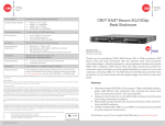
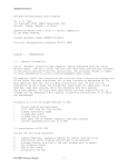
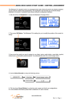
GreenArrays ™ AN004 Getting Started with Eval Board EVB001 Application Note AN004 Revised 10/08/11 Getting Started with Evaluation Board EVB001 The GreenArrays EVB001 Evaluation Board is a versatile and powerful application development platform for the GA144-1.20 chips. As such it has many configuration options. The current Printed Circuit Board (PCB) revision shown on the silkscreen is 0.1.1, and it is currently shipped with a starter eForth that may be booted from flash and with configuration settings as shown herein. Please familiarize yourself with this information before connecting anything to your new board. It will walk you through initial connection, check-out and use of the board. In addition, please download and read the other relevant documentation such as the Programmers' Reference for the F18 computers (DB001), the G144A12 Chip Data Book (DB002), the Evaluation Board Data Book (DB003), and the Programmers' References for arrayForth™, eForth, polyFORTH®, and other software as appropriate. The current editions of all GreenArrays documents, including this one, may be found on our website at http://www.greenarraychips.com . It is always advisable to ensure that you are using the latest documents before starting work. Your satisfaction is very important to us! Please contact [email protected] if you have questions or need help with using your board. In this edition, the photographs have been improved for greater clarity. Contents 1. Initial Check-Out ................................................................................. 2 1.1 1.2 1.3 1.4 1.5 1.6 Recommended Working Area ...................................................................................... 2 Factory Default Jumper Settings .................................................................................. 2 Check the Power Supply .............................................................................................. 3 Identify and Set-up COM Ports for USB A, B, C ............................................................. 4 Simple Confidence Test using eForth ........................................................................... 4 Test GA144 Chips ......................................................................................................... 4 2. Move On to Programming .................................................................. 5 3. Resources and Details ......................................................................... 5 3.1 3.2 3.3 What's in the Box ........................................................................................................ 5 Getting Help ................................................................................................................ 5 Errata in Current PCB Revision ..................................................................................... 5 AN004 Getting Started with Eval Board EVB001 1. Initial Check-Out This section outlines procedures for inspecting a board and verifying its configuration and function. These procedures are very similar to those we follow in the factory before shipping boards to you. 1.1 Recommended Working Area Since the purpose of this board is to provide you with direct access to the very sensitive pins of your chips, you should set up a working area to protect the chips against Electrostatic Discharge (ESD) from your body. We recommend, as a basic precaution, that you use an antistatic mat connected to a single-point earth ground in common with any other equipment in use, and that you wear a wrist strap, as shown in the adjacent photo, while handling or probing the board. It is always a good idea to avoid wearing clothing that tends to accumulate static charges, and to touch the mat or a grounded part of the board when approaching the work area and before touching other parts of the board. Note that the metal shield of the SD card slot is a good ground for this purpose; the shields of the USB connectors are not grounded in rev 0.1.1. If you have any questions about correct procedures, please check our website or contact the hotline for more information 1.2 Factory Default Jumper Settings Begin by setting all jumpers to the default settings as we shipped the board to you. Please refer to this illustration and to the detailed information that follows: 2 Copyright© 2010-2011 GreenArrays, Inc. 10/08/11 AN004 Getting Started with Eval Board EVB001 1.2.1 Table of Jumpers Host and Target Power Select J10 1 2 3 J11 1 2 3 J23 External Host Pwr VDDC to Host External Host Pwr VDDI and A to Host Main 1.8v Bus J14 1 2 3 External Target Pwr VDDC to Target Main 1.8v Bus J15 1 2 3 External Target Pwr VDDI to Target Main 1.8v Bus J16 1 2 3 USB Port Data Connections to Chips From Port A To Port A From Port B To Port B From Port C To Port C 1 3 5 7 9 11 2 4 6 8 10 12 Host 708.17 Host 708.1 Host 200.17 Host 100.17 Target 708.17 Target 708.1 Target Chip Reset J22 Host 500.17 USB C RTS signal Target reset circuit 1 3 5 2 4 6 Target RESETpin SD/MMC Socket Signals Socket pins CLK/SCLK DAT3/CSCMD/SI DAT0/SO VDD J38 1 2 3 4 5 J40 1 2 3 4 5 SPI bus signals SPI CLK MMC SPI CS- MMC SPI DO SPI DI 1.8v Host-Target Communication J35 1 2 Host 300.17 Target 300.17 J34 1 2 Host 300.1 Target 300.1 Host Chip Reset and Boot External Target Pwr VDDA to Target Main 1.8v Bus SPI Bus Expansion J20 RESET pin USB A RTS J25 1 2 3 J26 1 2 1 3 2 4 RESET pin Reset ckt & J25.3 Ground SPI Flash RST- pin Host reset ckt & J20.4 J39 1 2 3 Host 600. 17 FLASHENABLEGround FLASH ENABLE- on SPI bus. J37 1 2 3 4 Inputs to NAND. Output low enables MMC on SPI bus. Host 705.17 NO BOOT when IN 1.3 Check the Power Supply In the factory, we check the power supply before applying DC power to most of the board. Begin by removing all of the power select jumpers J10, J11, J14, J15 and J16 as shown here. Connect a voltmeter as shown; all four pins of header J29, near the Target chip, are ground and pin 3 (right side) of any of the power select headers is connected to the output of the on-board switching regulator. After setting the board up in this way, provide input power to the regulator, using either a "wall-wart" in J2 or any of the three USB connections J3, J9 or J18. Your voltmeter should indicate very nearly 1.8 volts. We do not recommend checking resistance between VDD and ground on this board, because many meters apply high voltages exceeding many chips' limits. When the checks are complete, re-insert the power select jumpers. If you use a "wall-wart" power source, it needs to provide 3.6 to 19.5 volts (a lower limit of 4v is more practical) on a type "N" connector, positive voltage on center pin. If the supply can produce 4.5 to 5 watts then it should be able to power the 80% efficient switching regulator at its maximum rated output of 2A at 1.8v. Copyright© 2010-2011 GreenArrays, Inc. 10/08/11 3 AN004 Getting Started with Eval Board EVB001 1.4 Identify and Set-up COM Ports for USB A, B, C Each USB connector identified as A, B, and C reading left to right goes to an FTDI USB to serial adaptor chip. These have unique serial numbers for the benefit of systems that use them to assign a permanent COM port number to each device. If using Windows or Parallels, attach the cables one at a time, identify the COM port numbers, and using Device Manager find Advanced Port Settings. Change Latency Timer from default 16 ms to 1 ms, and change USB Transfer Sizes from default 4096 to 128 bytes. These settings will greatly improve performance. Subsequently each port may be used at any baud rate from 19,200 to 921,600. See the arrayForth User's Manual installation sections for more information and for other platforms. Please contact us right away if this information does not meet your needs. However you do it, you must keep track of which COM port numbers connect to which of the board's USB ports. 1.5 Simple Confidence Test using eForth Connect any serial terminal emulator program such as PuTTY or HyperTerm to USB port B, 8 data bits, no parity, one stop bit and no flow control. Remove NO-BOOT jumper J26 and press the host chip reset button (C0-RST) on the lower left corner of the board, then hit the space bar on the terminal to auto-baud eForth. The terminal should display this: eForth btc:20110826 ga144:20110826 ok Hit the enter key. You should see another ok which indicates that a great deal of the board is working. Please contact us right away if you do not see these things! 1.6 Test GA144 Chips To completely self-test the chips, download the arrayForth User's Manual and the current Windows Installer from our website (see 3.2 below). Follow instructions in the User's Manual for your host platform to install the arrayForth software and identify and configure your COM ports. You do not need to edit the colorForth code at this point but you do need to get the COM ports identified and the connections to USB ports A and C configured as instructed for your platform. With USB ports A and C connected, and with NO-BOOT jumper J26 installed, run arrayForth as per instructions for your platform. Type the following phrases to run self-tests, substituting the actual COM port for USB A (host IDE) for 10 and the port for USB C (target IDE) for 12: 10 selftest 12 selftest 10 autotest (runs factory tests on host chip) (runs factory tests on target chip) (tests target chip under host chip control using synchronous boot, and tests SERDES between the chips) Each word or number is entered by the space or ENTER keys. To delete a word or number before entering it, use backspace. While a test is running you will see a screen like the one shown here. The "test status" is initially busy in grey, and while the test is running the green numbers following the the magenta variable names are updated as the testing progresses. When testing is completed, the busy status changes to ok! as shown in green, or fail! in red. The expected result is, obviously, ok! . Please contact us right away if you do not see the expected results or if you have any difficulty in running these tests! 4 Copyright© 2010-2011 GreenArrays, Inc. 10/08/11 AN004 Getting Started with Eval Board EVB001 2. Move On to Programming Now that you've verified the integrity of your board and its connections with a host machine, it's time to take a closer look at the three main development tools used in programming our chips. arrayForth is currently the main tool for working with F18 code: Editing its source in colorForth representation, compiling it, making HTML listings, debugging it interactively using the IDE, generating boot streams, and writing flash. This system is written in the Intel IA32 instruction set (x86) and runs on Microsoft Windows systems (including Windows hosted by Mac Parallels), as well as unix systems using WINE. eForth is a very simple and portable implementation of ANS Forth. This particular implementation runs on a 16-bit Virtual Machine that runs on our chips. eForth requires only a terminal emulator on USB port B, although the supplied emulator provides additional useful capabilities. polyFORTH is a full blown, self -reproducing professional application development operating system that also runs on a Virtual Machine programmed for our chips. Mass storage is provided by the evaluation board and terminal services by an external system. Eventually all the F18 programming tools will be implemented by this polyFORTH system. Please see our website for to download these tools, their documentation, and other relevant code, documentation and application notes. 3. Resources and Details 3.1 What's in the Box In addition to the Eval Board itself, there is an antistatic bag containing parts you may find useful. The exact composition of this bag is subject to change, but as of the time of this writing it contains the following items: One Dual voltage, 2 GB MMC card intended for use as primary mass storage by polyFORTH when that system is released. One USB cable. Two Clip-leads. One each DB9, RJ48, and USB-B sockets. Three TRS audio jacks. Long single and double row male headers that may be cut up and soldered where needed. Five LEDs and five 47Ω resistors for diagnostic and general use. 3.2 Getting Help There is a special webpage for customers who have bought our evaluation boards; please visit it now at this URL: http://www.greenarraychips.com/home/support This page is updated frequently and will always have the latest information for you. Email [email protected] for prompt replies to your questions. The hotline team will provide you with additional contact information for direct, personal support such as Skype ID and phone numbers upon request. General documentation and downloads are posted in http://www.greenarraychips.com/home/documents 3.3 Errata in Current PCB Revision PCB REV 0.1.1 The FTDI transmit and receive LEDs are not populated due to an error in circuit design. FIX OR WORK-AROUND Do not use J70. The pattern and wiring will be corrected in the next board revision. Do not use. Circuit and layout will be corrected in the next board revision. 0.1.1 The general purpose LEDs (see J57) are not populated due to an error in circuit design. Do not use. Circuit and connectors will be changed in the next board revision. 0.1.1 DESCRIPTION The VGA connector hole pattern J70 is rotated 180 degrees.. Copyright© 2010-2011 GreenArrays, Inc. 10/08/11 5 GreenArrays ™ Application Note AN004 Revised 10/08/11 IMPORTANT NOTICE GreenArrays Incorporated (GAI) reserves the right to make corrections, modifications, enhancements, improvements, and other changes to its products and services at any time and to discontinue any product or service without notice. Customers should obtain the latest relevant information before placing orders and should verify that such information is current and complete. All products are sold subject to GAI’s terms and conditions of sale supplied at the time of order acknowledgment. GAI disclaims any express or implied warranty relating to the sale and/or use of GAI products, including liability or warranties relating to fitness for a particular purpose, merchantability, or infringement of any patent, copyright, or other intellectual property right. GAI assumes no liability for applications assistance or customer product design. Customers are responsible for their products and applications using GAI components. To minimize the risks associated with customer products and applications, customers should provide adequate design and operating safeguards. GAI does not warrant or represent that any license, either express or implied, is granted under any GAI patent right, copyright, mask work right, or other GAI intellectual property right relating to any combination, machine, or process in which GAI products or services are used. Information published by GAI regarding third-party products or services does not constitute a license from GAI to use such products or services or a warranty or endorsement thereof. Use of such information may require a license from a third party under the patents or other intellectual property of the third party, or a license from GAI under the patents or other intellectual property of GAI. Reproduction of GAI information in GAI data books or data sheets is permissible only if reproduction is without alteration and is accompanied by all associated warranties, conditions, limitations, and notices. Reproduction of this information with alteration is an unfair and deceptive business practice. GAI is not responsible or liable for such altered documentation. Information of third parties may be subject to additional restrictions. Resale of GAI products or services with statements different from or beyond the parameters stated by GAI for that product or service voids all express and any implied warranties for the associated GAI product or service and is an unfair and deceptive business practice. GAI is not responsible or liable for any such statements. GAI products are not authorized for use in safety-critical applications (such as life support) where a failure of the GAI product would reasonably be expected to cause severe personal injury or death, unless officers of the parties have executed an agreement specifically governing such use. Buyers represent that they have all necessary expertise in the safety and regulatory ramifications of their applications, and acknowledge and agree that they are solely responsible for all legal, regulatory and safetyrelated requirements concerning their products and any use of GAI products in such safety-critical applications, notwithstanding any applications-related information or support that may be provided by GAI. Further, Buyers must fully indemnify GAI and its representatives against any damages arising out of the use of GAI products in such safety-critical applications. GAI products are neither designed nor intended for use in military/aerospace applications or environments unless the GAI products are specifically designated by GAI as military-grade or "enhanced plastic." Only products designated by GAI as militarygrade meet military specifications. Buyers acknowledge and agree that any such use of GAI products which GAI has not designated as military-grade is solely at the Buyer's risk, and that they are solely responsible for compliance with all legal and regulatory requirements in connection with such use. GAI products are neither designed nor intended for use in automotive applications or environments unless the specific GAI products are designated by GAI as compliant with ISO/TS 16949 requirements. Buyers acknowledge and agree that, if they use any non-designated products in automotive applications, GAI will not be responsible for any failure to meet such requirements. The following are trademarks of GreenArrays, Inc., a Nevada Corporation: GreenArrays, GreenArray Chips, arrayForth, and the GreenArrays logo. polyFORTH is a registered trademark of FORTH, Inc. (www.forth.com) and is used by permission. All other trademarks or registered trademarks are the property of their respective owners. For current information on GreenArrays products and application solutions, see www.GreenArrayChips.com Mailing Address: GreenArrays, Inc., 774 Mays Blvd #10 PMB 320, Incline Village, Nevada 89451 Printed in the United States of America Phone (775) 298-4748 fax (775) 548-8547 email [email protected] Copyright © 2010-2011, GreenArrays, Incorporated