1
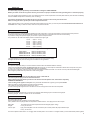
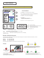
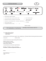
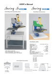
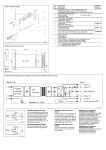
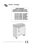
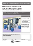
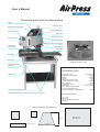
User´s Manual
Pneumatic press with two base platens
Display
Pressure indicator
Temperature and time setting
Pressure adjustment
Pressure switch ON
Main switch
Circuit breaker 12 A
Emergency switch
Pressure switch OFF
Connection cable from heat platen
Clamping bolts
for heat platen
Grease nipples
Base platen
Heat platen
Base platen
Replaceable plates for caps
Clamping mechanism
for the caps
TECHNICAL DATA
Dimensions in cm:
170 x 60 x 85
Weight with cabinet stand:
160 kg
Voltage:
230VAC
Power:
2 KW
Air demand per work cycle:
3,3 l
Pressure efficiency at 6 bar:
2490 kg
Max. pressure:
6 bar
Temperature range:
0 - 220 °C
Time range:
0 - 9 min. 59 sec.
Max. variation of temperature
of the heat platen at 180°C
(interior temperature of heat platen):
-1/+3°C
Cabinet stand
Clamping bolts 4 pieces M10
Use clamping bolts to bolt the cabinet stand and the press together
Replaceable heat platens
10 x 13 cm
20 x 20 cm
38 x 45 cm standard version
40 x 50 cm
Replaceable base platens
20 cm
12 x 12 cm
38 cm
20 x 20 cm
10 x 45 cm
38 x 45 cm
40 x 50 cm
43 cm
1
SWITCH ON
This device may only be operated by trained staff after reading the USER’s MANUAL.
Before you switch on the device, please check if your socket is in proper condition and if the grounding wire is connected properly.
The green toggle switch activates the press. The display shows the current temperature of the heat platen and the press will heat immediately
until the indicated temperature is reached ( LED 1 is shining).
Connect the compressed air hose with the device. The max. pressure in the line may not exceed 6 bar.
When not using the device, please pull out the compressed air hose.
When using the device over a period of several days without switching it off, then you have to press the black knob left underneath the air
connection once a day, to drain the water, which has composed in the filter.
PRESSURE ADJUSTMENT
The contact pressure is changed through operating the right push-button. Turning the push-button to the right will increase pressure.
Turning the push-button to the left will decrease pressure. Impressing the push-button will freeze the current setting.
If you want to change the pressure again you will have to pull out the push-button.
The pressure can be read off the display which is located in the upper right.
1,0 bar
2,0 bar
3.0 bar
4.0 bar
5.0 bar
6.0 bar
-
approx. 415 kg
approx. 830 kg
approx. 1245 kg
approx. 1660 kg
approx. 2075 kg
approx. 2490 kg
It is recommended to use the following pressure settings:
Caps option:
Platens 20 x 20 cm
Platens 38 x 45 cm
Platens 40 x 50 cm
from 0,2
from 0,2
from 0,5
from 0,5
to max. 0,6 bar
to max. 1,0 bar
to max. 4,0 bar
to max. 4,5 bar
After each change you should close the press once to check the new pressure setting.
Damages due to excess pressure settings are excluded from the guarantee.
SAFETY
For optimum output and safety it is recommended to read and follow the USER’s MANUAL carefully.
Please note that only one person is allowed to work with the press. No second person is allowed to stand next to the press at any time.
In case of an emergency push the EMERGENCY SWITCH immediately.
By pushing the emergency switch the press will open immediately and block the switch. You cannot move the press downwards again.
The emergency switch has to be pulled out to start working again.
MAINTENANCE
All maintenance works should be done when the device is switched off.
You have to pull the plug out of the socket beforehand.
When replacing the heat platens you will have to wait until the heat platens have cooled down completely.
DANGER OF BURNING !!!
There are two grease nipples on the press. They should be lubricated with a grease gun every four weeks.
Make sure that the grease infiltrates the bearing when lubricating.
The grease has to be temperature-resistant up to 160° C.
You can find the grease nipples down at the stack on the left and right as well as above the heat platen.
CLEANING
The device should be cleaned with a soft cloth. Use domestic dish washing liquid or window cleaning liquid.
Scrubbing sponges, solvents or petrol are not recommended.
REPLACE SILICONE PAD
The device has to be cold.
Remove old silicone pad completely from the base platen.
Use a pallette knife to equally spread out temperature-resistant silicone. Then apply the new silicone pad.
Base plate
straight:
Put a plate onto the silicone pad and load with weights (approx. 20kg).
Let dry for 24 hours.
Part for caps:
Apply cold heat platen onto the new silicone pad. Fix both plates with paper adhesive tape.
Let dry for 24 hours.
The silicone pad should be about 1-2 cm bigger than the base platen. Use a cutter to cut edges off after you have sticked both plates together.
2
USER`s MANUAL
This press may only be operated by trained staff after reading the user’s manual.
PROGRAMMING
Temperature
Contact pressure
17 x 7 cm
20 x 20 cm
38 x 45 cm
2
max.0,6 bar
3. Use buttons -2 or +3 to set new temperature.
Confirmation
max.1,0 bar
2,0 bar
max.4,0 bar
2,5 bar
40 x 50 cm
1. Hold button 1 for 5 seconds until LED 1 is blinking.
2. LED 1 is blinking and the display shows the preset temperature.
The programming mode has been switched on.
Time
0,3 bar
0,6 bar
3
max.4,5 bar
Programming
1. Confirmation 5 sek.
2. Temperature +/3. Confirmation 1 sek.
4. Time +/5. Confirmation 1 sek.
6. Done
1
4. Press button 1.
The display shows the preset time.
Change time setting with buttons -2 or+3.
5. Press button 1 to switch off programming mode.
LED 1 - The press is heating.
LED 2 - Blink diode, programming mode switched on.
LED 3 - Temperature range (not active)
LED 4 - Temperature setting (not active)
The temperatur in °C
Example:
The time setting is 15 seconds.
Minutes
Press button 2, the preset time setting is shown on the display.
Max. time setting is 9 minutes 59 seconds.
TIME
TEMPERATURE
Press button 3, the preset temperature is shown on the display.
Example: Settings for the press
This press is used to apply transfers and transfer foils on textiles. Please get in touch with the manufacturer of the textiles, in order to
achieve good results. Some settings:
Foil Flex Foil Flex S Foil Flock Foil Velcut-
150° - 160° C time 12 sec.
155° - 160° C time 12 sec.
150° - 160° C time 15 sec.
150° - 160° C time 15 sec.
All information without engagement. Please arrange own tests before manufacturing.
OFF
OFF
Control
PRE-PRESS
To open the press before time is up, push the two yellow
OFF-buttons at the same time and hold them until the heating
platen has reached its top position. Do not swing the press
aside until the heat platen has fully stopped.
EMERGENCY SWITCH
ON
ON
Pneumatic
PRESS
In case of a danger situation push the red button
in front of the press.
The press will open automatically.
Pull the red plug out to start working again.
Push the green buttons at the same time and hold until
the heat platen has moved to its lowest position.
The press will open automatically after preset time is over.
3
4
1F25
FILTER
3
1
Stecker/Wtyczka/plug
7
Temperatur(e)sensor
4
230W
Heizplatte/plyta grzewcza/heat platen 8 x 16 cm
230W
Heizelement/grzalka/heating element
6
S1 time start. . . . . . . . . . . (czarny / schwarz / black )
S4 setup . . . . . . . . . . . . . . . . . . . (zolty / gelb / yellow )
S5 [ - ] Temperatur(e) . . . . . . . . . (zielony / grün / green)
S6 [ +] Zeit / time . . . . . . . . . . . . (Brazowy / braun / brown)
Temperatur(e)sensor ( - ). . . . . . . .(niebieski / blau / blue)
Temteratur(e)sensor (+). . . . . . . . . (czerwony / rot / red)
F1 bezpiecznik / Sicherung / fuse 10A
F2 bezpiecznik / Sicherung / fuse 12VDC 1,5A
12V+ czerwony / rot / red
12V- niebieski/ blau / blue
3 + 6 grzalka / Heizelement / heating element
1 + 4 czujnik / Temperatur(e)sensor
7 uziemienie / Schutzleitung / grounding wire
S10 Hauptschalter/ Wlacznik glówny / main switch
N
0
F1
Power supply unit
czerwony/ rot/red +
Temperatur(e)sensor
czarny
schwarz 230VAC
black
4
5
6
Stecker/Wtyczka/plug
F2
1,5A
7
1
2
3
-
12VDC
+
3
12VDC
230VAC
6
CRYDOM 50A
+
CRYDOM
K
F
S S1
ROM-3
A3K1 Z 540
Temperatursicherung/
thermal fuse
1
4
0 - 220°C
7
S2
Zusatzschalter/
additional switch
Temperatur(e)sensor
KTY 84-1
Stecker/wtyczka/plug
Relais 50A
Przekaznik
elektroniczny
relay
+ -+ -
12VDC
Thermoregulator-timer
niebieski/ blau/blue
Heizelement/grzalka/heating element
Temperatur(e)sensor Heizplatte/plyta grzewcza/heat platen
2000W
czarny
schwarz 230VAC
black
Netzteil/zasilacz 12VDC
SCHALTPLAN POLACZEÑ
SCHEMATIC (Electrical Diagram)
blau
L
S10
Setup
230VAC
Zeit aus 12V+
Time off
S1
S6
S5
S4
Rot/czerwony/red
10
Blau/niebiesk/blue
13
Blau/niebieski/blue
Mikroschalter/micro switch
Aktiviert die Schaltung nur in Position
über der Arbeitsplatte.
Only activates the circuit above the
base platen.
7
6
Rot/czerwony/red
+ 12V
- 12V
230VAC
11
Ein/ON
Ein/ON
Rot/czerwony/red
Druckschalter EIN
Pressure switch ON
Elektromagnet/
electro magnet
+
12
+
-
Rot/czerwony/red
8
9
Bewegung der
Heizplatte
Movement of
heat platen
2
Rot/czerwony/red
Druckschalter EIN
Pressure switch ON
Rot/czerwony/red
Rot/czerwony/red
14
Rot/czerwony/red
S1
5
Mikroschalter
Micro switches
Weiß/bialy/white
3
Rot/czerwony/red
Zeit aus 12V+
Time off
+-+12V
44
Weiß/bialy/white
33
Weiß/bialy/white
S2
Weiß/bialy/white
S2
Druckschalter AUS/
Pressure switch OFF
K
S S1
F
CRYDOM
Weiß/bialy/white
Druckschalter AUS/
Pressure switch OFF
ROM-3
0 - 220°C
0
10
Rot/czerwony/red
1
4
Setup
Netzgerät/Zasilacz/power supply
Zweihandrelais
Wlacznik Obureczny
two-hand relay
Control of pneumatic for Airpress
Blau/niebieski/blue
Pneumatikventil/pneumativ valve
Druckmesser/
pressure gauge
Druckzylinder/
printing cylinder
Heizplatte/heat platen
+
Druckluft max.6 bar/
compressed air max. 6 bar
5
E
TESTING REPORT
vis-CAP
vis-PRESS4050
o
Base (varnish, greasing of shafts)
o
Heat and base platens, symmetry, silicone, teflon
o
Hours of work at 220°C . . . . . . .
o
Electrical connection, grounding wire, power cable
o
Test with transfer foil
o
Electronics, max temperature 220° C, inspection of all functions o
o
Hours of work at 180 °C . . . . . . .
o
Temperature tolerance at 180°C . . . . - / . . . . . +°C
Warning stickers
o
Packaging
Serial number . . . . . . . . . . . . . . . . . . . .
EC declaration of conformity
According to the EC directive 89/37 EC
The Walter Schulze GmbH
Schmalenbachstr.15
12057 Berlin
hereby declares as European agent for the manufacturer Romanik that the following described machine:
heat press. . . . . . . . . . . . . . . serial number . . . . . . . . . . . .
accords to the terms of the following EC directives:
Machine directive ( 89/37)
Low voltage directive (72/23)
EMV-directive (89/336)
Used standards and technical specifications:
EN 292-1, EN 292-2 “safety of machines”
EN 60204-1 “electrical equipment of machines”
Berlin . . . . . . . . . .
__________________________
Peter Meidinger
CEO
6