1
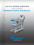
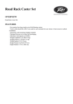
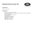
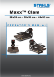
AUTO OPEN SERIES CLAM/HOVER PRESS ™ O P E R A T O R’ S M A N U A L HOVER PRESS™ 11″ x 15″ 16″ x 20″ 16″ x 16″ Safety Instructions When using your heat press, basic precautions should always be followed, including the following: 1. Read all instructions. 2. Use heat press only for its intended use. 3. To reduce the risk of electric shock, do not immerse the heat press in water or other liquids. 4. Never pull cord to disconnect from outlet, instead grasp plug and pull to disconnect. 5. Do not allow cord to touch hot surfaces, allow heat press to cool completely before storing. 6. Do not operate heat press with a damaged cord, or if the equipment has been dropped or damaged. To reduce the risk of electric shock, do not disassemble or attempt to repair the heat press, take it to a qualified service person for examination and repair. Incorrect reassembly or repair could cause a risk of fire, electric shock, or injury to persons when the equipment is used. 7. Close supervision is necessary for any heat press being used by or near children. Do not leave equipment unattended while connected. 8. Burns can occur when touching hot metal parts. 9. To reduce the likelihood of circuit overload, do not operate other high voltage equipment on the same circuit. 10. If an extension cord is necessary, then a 20 amperage rated cord should be used. Cords rated for less amperage may overheat, care should be taken to arrange the cord so that it cannot be pulled or tripped over. SAVE THESE INSTRUCTIONS SERVICE HOTLINE: 800.727.8520 AUTO OPEN Table of SERIES Contents Safety Instructions 2 Machine View 4 Control Panel Guide 5 Operating Instructions 6-12 Connecting the System Turning the System On Adjusting the Temperature Adjusting the Time Adjusting the Pressure Printing and Pressing (Auto Open Clam) Pressing (Hover Press™) 6 7 8 9 10 11 12 Auto Open Clam/Hover Press™ Overview 13 Replacement Parts List and Location Guide 14-17 HOTRONIX.C OM Electrical Schematic 18 Contact 19 AUTO SERIES MachineOPEN View FRONT VIEW LED Display Located on the opposite side of the press Circuit Breaker Power Supply Lift Handle SIDE VIEW 12V Magnet Over-the-Center Pressure Adjustment Knob Power ON/OFF Switch ON PAGE 4 OFF SERVICE HOTLINE: 800.727.8520 AUTOControl OPEN SERIES Panel Guide Digital Display Temperature Indicator Set Indicator Time Indicator Pressure Indicator Increase Mode Select Decrease HOTRONIX.C OM PAGE 5 AUTO OPEN SERIES Operating Instructions A U T O O P E N C L A M / H O V E R P R E S S™ The Auto Open Clam/Hover Press™ Operating Instructions are designed with the user in mind. Carefully read and follow the step-by-step instructions for best results. To avoid burns, do not touch the heated platen during use. Keep hands clear of the upper platen of the press during platen lock down as the pressure may cause injury. Press should be placed on a sturdy, suitable stand at least 36”L x 24”W x 29”H. Work area must be kept clean, tidy and free of obstructions. Power supply cord must be disconnected before cleaning or servicing press. Connecting the System 1. CONNECT THE POWER CORD 1.1 Connect the power cord into a properly grounded electrical outlet with a sufficient amperage rating. VOLTAGE 120 Volt - The Auto Open Clam/Hover Press™ requires a full 20 amp grounded circuit for 120 volt operation. 240 Volt - The Auto Open Clam/Hover Press™ requires a full 10 amp grounded circuit for 240 volt operation. EXTENSION CORDS If used, should be as short as possible and not less than 12 gauge. Heavy duty cords are recommended. CIRCUITS that have less than 15 amps or that have other high demand equipment or appliances (especially more than one heat seal machine) plugged in, should not be used. NOTE: If the supply cord is damaged, it must be replaced by the manufacturer, its service agent or a similarly qualified person in order to avoid hazard. Use HSJ type, rated 250 V - 10 AMP for replacement. CAUTION Failure to follow these instructions will cause: 1. Erratic controller functions. PAGE 6 2. Inaccurate displays and slow heat-up. 3. The circuit breaker to disengage. SERVICE HOTLINE: 800.727.8520 AUTO OPEN SERIES Turning the System On 2. SWITCH THE SYSTEM ON See the diagram below for switch placement. Locate the packaging bolt positioned on the top-center of the press. Packaging bolt must be removed prior to turning the press on or operating the press. Now, locate the Power ON/OFF Switch on the side of the press, then turn the Power Switch on. Power ON/OFF Switch ON HOTRONIX.C OM OFF PAGE 7 AUTO OPEN SERIES Adjusting the Temperature 3. ADJUST THE TEMPERATURE Locate the LED Display on the Press. 3.1 Press the Mode Select button located in the center of the Control Panel. The (SET) and (TEMP) lights located next to the display will illuminate indicating you are in the adjust temperature mode. 3.2 Next, press the (-) button located to the left of the Mode Select button to lower the temperature setting, or press the (+) button located to the right of the Mode Select button to raise the temperature setting. The temperature can be set from 170° F (76° C) to 430° F (220° C). The LED will display changes as you make them. Digital Display Temperature Indicator Set Indicator Time Indicator Pressure Indicator Increase Mode Select Decrease PAGE 8 SERVICE HOTLINE: 800.727.8520 AUTO OPEN SERIES Adjusting the Time 4. ADJUST THE TIME The Auto Open Clam/Hover Press™ has two time settings. This will allow you to set different times when a two step application is required. For single hit applications, you simply set both time settings the same. Once you have adjusted the temperature, press the Mode Select button again. This will advance you to the Time #1 mode. The set and time lights will illuminate, indicating that you are in the Time # 1 mode. Adjust the time in the same manner that you adjusted the temperature. Once you have the Time # 1 set, push the Mode Select button again to advance to the Time # 2 setting. All three red LED lights will illuminate indicating that you are in the Set Time # 2 Mode. Select the desired time and push the Mode Select button again to exit the time settings. All lights will be off and the press will return to the print mode. REMEMBER: Press the Mode Select button ONCE to advance to the Adjust Temperature Mode Press the Mode Select button A SECOND TIME to advance to the Time #1 mode. Press the Mode Select button A THIRD TIME to advance to the Time #2 Settings. Press the Mode Select button A FOURTH TIME to return to the Heat Up/Operating Mode. HOTRONIX.C OM PAGE 9 AUTO OPEN SERIES Adjusting the Pressure 5. ADJUST THE PRESSURE First, locate the LED Display on the Press. (See figure 1) The Pressure Adjustment Knob is located in the center of the heat platen (See figure 2) Adjust the pressure by turning the knob clockwise to increase pressure and counter clockwise to decrease pressure. PRESSURE READOUT A visual Pressure Readout is located on the lower right side of the LED Display. When the handle is locked into the Print Position, a pressure number will be displayed. Readout will be on a scale of 0 - 9. A 0 Pressure readout would indicate no pressure at all and 9 would indicate very heavy pressure. (See figure 1) Figure 1 1 - 3 = Light Pressure 4 - 7 = Medium Pressure 8 - 9 = Heavy Pressure To adjust the Pressure, simply turn the Pressure Adjustment Knob to the right or clockwise to increase the Pressure and to the left or counter clockwise to decrease the Pressure. The readout will display the Pressure when locked down in the print position. REMEMBER: To allow for the thickness of your garment when adjusting the pressure. Pressure Adjustment Knob Figure 2 WARNING: Structural damage caused by excessive pressure is not covered under the limited warranty! PAGE 10 SERVICE HOTLINE: 800.727.8520 AUTO OPEN SERIES Printing / Pressing 6a. PRESS (FOR AUTO OPEN CLAM ONLY) NOTE: This step pertains to the Auto Open Clam Press only. For printing/pressing instructions on the Hover Press™, please refer to page 12. Once your equipment has reached the designated temperature: Position the garment and application and proceed to press. Lower and lock the heat platen into the press position. This procedure will start the automatic timing process. The timer will automatically count down and lift the heat platen into the “UP” position when the press cycle is complete. NOTE: Please be aware after time is complete, gas shocks will automatically release the platen into the “UP” position. The time will automatically re-set and you are ready to continue with the next application. HOTRONIX.C OM PAGE 11 AUTO OPEN SERIES Printing / Pressing 6b. PRESS (FOR HOVER PRESS™ ONLY) NOTE: This step pertains to the Hover Press™ only. For printing/pressing instructions on the Auto Open Clam, please refer to page 11. Your Hover Press™ can be set up to utilize four different settings on hover or direct pressure. The options are listed below: 001 = Pressure 002 = Hover 003 = Hover 004 = Pressure (Time 1) (Time 1) (Time 1) (Time 1) Pressure Pressure Hover Hover (Time 2) (Time 2) (Time 2) (Time 2) Once you have decided what setting is best for your application (1,2,3 or 4), follow the simple steps below: 6.3 With Power switched to OFF position, hold down both Decrease (-) and Increase (+) mode buttons on the Control Panel. Switch power to ON position and continue to hold mode buttons down for 3-5 seconds. 6.4 Press the Mode (center) button once. The number 555 should appear on the display. 6.5 Press the mode (center) button again, at this time you may choose option 1,2,3 or 4 by pressing the increase (+) button. Once desired setting is selected, press the mode (center) button twice to return to the temperature mode (step 3). 6.6 Once your equipment has reached the designated temperature, position the garment and application and proceed to press and/or hover. 6.7 Lower and lock the heat platen into the press position. This procedure will start the automatic timing process. 6.8 The timer will automatically count down and lift the heat platen into the “UP” position when the first press or hover cycle is complete. Lower and lock the heat platen for the second press or hover cycle. The timer will automatically count down and lift the heat platen when the second cycle is complete. CAUTION: Please be aware after time is complete, gas shocks will automatically release the platen into the “UP” position. NOTE: The time will automatically re-set and you are ready to continue with the next application. PAGE 12 SERVICE HOTLINE: 800.727.8520 AUTO OPEN Auto Open Clam/Hover Press™SERIES Overview HOTRONIX® AUTO OPEN CLAM HOTRONIX® HOVER PRESS™ Patented, state-of-the-art auto open feature enables you to multi-task, helps avoid over application and ruined garments, bringing you the convenience of an airpress without an air compressor. Maximize the production of digital direct-to-garment printing with the new Hotronix® Hover Press™, a brand new patent pending heat press manufactured exclusively by Stahls’ Hotronix®. Includes digital time, temperature and pressure displays and allows the operator to set the press for two functions: hover or pressure. The Hotronix® Hover Press™ also features the Twin Timer™ function which allows the user to program two independent time settings to count down any two-step process without resetting the timer. 11” x 15” • Shipping Dimensions: 31”L x 21”W x 21”H • Shipping Weight: 72 lb 16” x 16” • Shipping Dimensions: 35”L x 25”W x 22”H • Shipping Weight: 90 lb. 16” x 20” • Shipping Dimensions: 35”L x 25”W x 22”H • Shipping Weight: 100 lb. 16” x 20” • Shipping Dimensions: 35”L x 25”W x 22”H • Shipping Weight: 100 lb. Features Features • Twin Timer feature • Patented, Magnetic Auto Open feature • Patented, Magnetic Assist Lock Down • 3/4” thick Teflon® coated upper platen • Digital time and temperature controls • Space saving clam shell design • Wide opening for easy layout • Quick change lower platen • Platinum RTD heat sensor • UL/ULC/CE/RoHS Compliant • Cast in tubular heating element every 2” to ensure no cold spots • Patented, Over-the-Center Pressure Adjustment • CE approved • Temp. range 170°- 430°F (76°-220°C) • °F or °C available ™ • New Twin Timer™ feature • Patented, Magnetic Assist Lock Down • Assisted Auto Open feature • Digital time and temperature controls • Live Digital Pressure Display • Twin Timer™ for Two Step Applications with the 999 second Dwell Time. • Patented, Over-the-Center Pressure Adjustment • Space saving clam shell design • Wide opening for easy layout • Platinum RTD heat sensor • UL/ULC/CE/RoHS Compliant • Cast in tubular heating element every 2” to ensure no cold spots • Temp. range 170°- 430°F (76°-220°C) • °F or °C available International voltage available, call for pricing LIFETIME WARRANTY on heating element • 5 yrs. on framework • 2 yrs. on circuit board • 1 yr. parts & labor HOTRONIX.C OM PAGE 13 AUTO OPEN SERIES Clam Replacement Parts List PAGE 14 Item # Part Name 1 2 3 4 A-B 5 6 7 A-B 7C 8 9 10 A-B 10 C 11 12 13 14 15 16 17 A 17 B 17 C 18 A 18 B 18 C 19 A 19 B 19 C 20 A 20 B 20 C 21 22 23 24 25 26 A-B 26 C 27 28 29 30 31 32 33 34 35 A-B-C 36 37 38 39 40 41 42 43 44 A-B-C 45 46 47 A-B-C 48 49 50 51 52 53 54 55 56 Hex Soc Button HD # 10 - 32 x 1/2” Rubber Foot Acorn Hex Nut Hex Cap HD Screw - 3/8“ -16 x 3/4” 16 x 20 Lock Spring Washer Hex Soc Screw 1/4 - 20 x 1 1/4” 16 x 20 Lower Platen Spacer Lower Platen Spacer Nylon Hex Nut Ball Stud - 10mm 16 x 20 Gas Spring Gas Spring Steel Spacer Bridle Links Nylon Washer Threaded Pin 1/4” - 20 x 3” PVC Spacer 1/2” I.D. x 2.48 Threaded Pin 3 5/8” x .5” Dia. _1/4” - 20 16 x 20 Lower Platen Lower Platen Lower Platen 16 x 20 Silicone Pad Silicone Pad Silicone Pad 16 x 20 Heat Platen Heat Platen Heat Platen 16 x 20 Heat Platen Cover Heat Platen Cover Heat Platen Cover Finish Washer Cover Screw 10 - 24 x 1/2” Adjustment Spindle Pressure Adj. Knob Safety Bolt “ - 18 x 4 1/2” 16 x 20 Elbow 90 degress with tubing Topaz Connector with flex tubing Hex Soc HD Shoulder Screw - 5/16” x 1/2” Steel Pin 1/2” Dia. x 4.38 Soc HD Cap Screw 1/4” - 20 x 3/8” Hex HD Nut - 1/4 “ - 20 Steel Pin - 1/2” Dia. x 6.45 PVC Spacer - 1/2” 1.D. x 1.1 Silicone Pad - 5/16“ 1.D. x 1 3/4” O.D. x 1/4” Electromagnet 16 x 20 Adjustment Arm Assembly JCN Nut Blue Foam Grip PVC Spacer 1/2” I.D. x 5” All Thread Pin - 1/4” - 20 x 4 3/4” Lift Links Hucap 1/2” Magnet Magnet Bracket 16 x 20 Handle Assembly Phillips Pan HD Screw - #6-32 x 1/2” STX Housing 16 x 20 Base Assembly Proximity Switch Terminal Block Triac Controller Bracket SSTT Control Board On/Off Switch Circuit Breaker Display Overlay Probe 16 x 16 16 x 16 11 x 15 16 x 16 11 x 15 16 x 16 11 x 15 16 x 16 11 x 15 16 x 16 11 x 15 16 x 16 11 x 15 16 x 16 11 x 15 16 x 16 11 x 15 16 x 16 11 x 15 16 x 16 11 x 15 Part # Qty. 3 - 1011 - 164 1 - 1256 3 - 1011 - 182 3 - 1011 - 41 2 - 1006 - 43 3 - 1011 - 62 1 - 1279 0140 2 - 1006 - 20 1 - 1939 1 - 2243 1 - 2246 1 - 2114 KIT 3 - 6906 1 - 1048 - 3 1 - 2091 1 - 2098 1 - 2092 2 - 1029 2 - 1059 3 - 1199 - 1 1 - 2136 1 - 2135 1 - 2134 2 - 1002 - 3 2 - 1015 3 - 1199 3 - 1332 3 - 1333 3 - 1331 1 - 1063 3 - 1011 - 217 2 - 1081 1 - 1012 3 - 1011 - 238 1 - 1940 1 - 1353 3 - 1011 - 233 1 - 2093 3 - 1011 - 215 2 - 1006 - 12 1 - 2094 1 - 2097 1 - 2104 1 - 1945 - 1 KIT 3 - 6903 2 - 1006 - 2 1 - 2115 1 - 2096 1 - 1042 - 1 KIT 3 - 6905 1 - 1107 - 1 1 - 1219 1 - 2085 KIT 3 - 6904 3 - 1011 - 152 4 - 1172 KIT 3 - 6901 1 - 1211 1 - 1290 1 - 1059 2 - 1661 1 - 2129 1 - 2087 1 - 1331 1 - 2018 - 1 1 - 1272 - 1 4 4 4 2 2 4 2 1 2 4 2 2 2 2 6 1 1 1 1 1 1 1 1 1 1 1 1 1 1 1 4 4 1 1 1 1 1 1 2 2 2 2 4 1 1 1 2 1 1 1 2 8 1 1 1 4 1 1 1 1 1 1 1 1 1 1 1 SERVICE HOTLINE: 800.727.8520 AUTO OPEN SERIES Clam Parts Location Guide The Auto Open Clam is available in three sizes: 16 x 20, 16 x 16, 11 x 15 When ordering replacement parts, refer to the following color codes For a 16″x20″ press - use color code A For a 16″x16″ press - use color code B For a 11″x15″ press - use color code C 26 A 26 C 20 A 20 B 20 C 19 A 19 B 19 C 18 A 18 B 18 C 17 A 17 B 17 C 7A 7C 10 A 10 C HOTRONIX.C OM PAGE 15 ™ AUTO OPEN SERIESParts List Hover Press Replacement Item # 1 2 3 4 5 6 7 8 9 10 11 12 13 14 15 16 17 18 19 20 21 22 23 24 25 26 27 28 29 30 31 32 33 34 35 36 37 38 39 40 41 42 43 44 45 46 47 48 49 50 51 52 53 54 55 56 57 58 59 60 PAGE 16 Part Name Hex Soc Button HD # 10 - 32 x 1/2” Rubber Foot Acorn Hex Nut Hex Cap HD Screw 3/8“ -16 x 3/4” Lock Spring Washer Hex Soc Screw 1/4 - 20 x 1 1/4” Lower Platen Spacer Nylon Hex Nut Ball Stud - 10mm Gas Spring Steel Spacer Bridle Links Nylon Washer Threaded Pin 1/4” - 20 x 3” PVC Spacer 1/2” I.D. x 2.48 Threaded Pin 3 5/8” x .5” Dia. _1/4” - 20 Lower Platen 16 x 20 Silicone Pad 16 x 20 Blue Heat Platen 16 x 20 Heat Platen Cover 16 x 20 Finish Washer Cover Screw 10 - 24 x 1/2” Adjustment Spindle Pressure Adj. Knob Safety Bolt “ - 18 x 4 1/2” Elbow 90 degress with tubing - 16 x 20 Hex Soc HD Shoulder Screw 5/16” x 1/2” Steel Pin 1/2” Dia. x 4.38 Soc HD Cap Screw 1/4” - 20 x 3/8” Hex HD Nut 1/4 “ - 20 Steel Pin 1/2” Dia. x 6.45 PVC Spacer 1/2” 1.D. x 1.1 Silicone Pad 5/16“ 1.D. x 1 3/4” O.D. x 1/4” Electromagnet Adjustment Arm Assembly JCN Nut Blue Foam Grip PVC Spacer 1/2” I.D. x 5” All Thread Pin 1/4” - 20 x 4 3/4” Lift Links Hucap 1/2” Magnet Magnet Bracket Handle Assembly Phillips Pan HD Screw #6-32 x 1/2” STX Housing Base Assembly Proximity Switch Terminal Block Triac Controller Bracket SSTT Control Board On/Off Switch Circuit Breaker Display Overlay Probe Hex Soc HD Shoulder Screw 5/16 x 1/2” Silicone Pad Hover Electromagnet Compression Spring Part # Qty. 3 - 1011 - 164 1 - 1256 3 - 1011 - 182 3 - 1011 - 41 2 - 1006 - 43 3 - 1011 - 62 1 - 1279 2 - 1006 - 20 1 - 1939 1 - 2243 1 - 2114 KIT 3 - 6906 1 - 1048 - 3 1 - 2091 1 - 2098 1 - 2092 2 - 1029 1 - 2136 2 - 1002 - 3 3 - 1332 1 - 1063 3 - 1011 - 217 2 - 1081 1 - 1012 3 - 1011 - 238 1 - 1940 3 - 1011 - 233 1 - 2093 3 - 1011 - 215 2 - 1006 - 12 1 - 2094 1 - 2097 1 - 2104 1 - 1945 - 1 KIT 3 - 6916 2 - 1006 - 2 1 - 2115 1 - 2096 1 - 1042 - 1 KIT 3 - 6905 1 - 1107 - 1 1 - 1219 1 - 2085 KIT 3 - 6904 3 - 1011 - 152 4 - 1172 KIT 3 - 6917 1 - 1211 1 - 1290 1 - 1059 2 - 1661 1 - 2129 1 - 2087 1 - 1331 1 - 2018 - 1 1 - 1272 - 1 3-1011-233 1-1561 1-2157 1-2163 4 4 4 2 2 4 2 2 4 2 2 2 6 1 1 1 1 1 1 1 4 4 1 1 1 1 1 2 2 2 2 4 1 1 1 2 1 1 1 2 8 1 1 1 4 1 1 1 1 1 1 1 1 1 1 1 2 1 1 1 SERVICE HOTLINE: 800.727.8520 OPEN SERIES Hover AUTO Press™ Parts Location Guide 44 42 32 37 43 25 40 28 34 13 36 24 33 41 38 60 39 35 32 56 27 29 26 30 22 23 21 55 53 20 46 54 19 45 18 31 17 48 14 15 57 7 12 16 13 6 41 9 11 10 9 12 8 47 5 4 HOTRONIX.C OM 3 2 1 58 59 PAGE 17 AUTO SERIES ElectricalOPEN Schematic US 120 V VERSION (1000 W for 11 x 15) (1000 W for 11 x 15) (240 V) US 240 V VERSION (1000 W for 11 x 15) GERMAN 240V VERSION PAGE 18 14 Contact Us Stahls’ Hotronix® One Paisley Park Carmichaels, PA 15320 U.S.A. Technical Support 800 . 727 . 8520 Monday - Friday 8am - 7pm EST Customer Service 800 . 727 . 8520 Monday - Friday 8am - 5pm EST Replacement Parts 800 . 727 . 8520 8am - 7pm EST Web Hotronix.com This document includes multiple trademarks and describes equipment covered by many patents that are owned by GroupeSTAHL and/or its subsidiaries. GroupeSTAHL enforces its rights to protect these intellectual properties. © 2011 Proudly made in the U.S.A. One Paisley Park . Carmichaels, PA 15320, U.S.A. Tech Support - Customer Service - Replacement Parts: 800 . 727 . 8520 Web: Hotronix.com