1
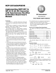
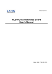
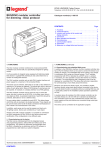
I-Chip Programmer
User ’s Manual
A. LCD and Buttons Illustrations
Power LED
S/N
Previous
Next
Read
Next
TYPE
AUX
-----------
-----
PWR
FUNC
TIMER
CH
Reset
Previous
Copy
Read
I-Chip Slot #1
Copy
Slot #1 LED
Power
I-Chip Slot #2
Light
Slot #2 LED
B. Choose Type Model
Press “1” for Flex EX model (go to page 2) and press “2” for Flex Mini model (go to page 5).
Page 1
Flex ES/EX Programming
C. Copy I-Chip
You can temporarily store the I-Chip information in the programmer unit if you do not have another
I-Chip on hand and then perform the copying at later dates.
Steps: Insert the original I-Chip onto I-Chip slot #1, press READ button to store the I-Chip information
into the programmer unit (red light will appear on the I-Chip LED and then green), insert a new I-Chip
onto the same I-Chip slot, press COPY button to transfer the previously stored I-Chip information into
the new I-Chip (red light appears on the I-Chip LED and then green), programming complete.
D. Duplicate I-Chip
If you have both the original I- Chip and an empty I-Chip on hand at the time of programming, rather
than store information into the programmer unit first then into the empty I-Chip, you can perform I-Chip
duplication altogether.
Steps: Insert the original I-Chip onto I-Chip slot #1, insert the new I-Chip onto slot #2, press COPY
button to transfer information from slot #1 to slot #2 (red light appears on both I-Chip LED and then
both green). Now both I-Chips are with identical information.
E. Program System Serial Number
Select system serial number by moving the black arrow on the LCD screen to the S/N location via the
NEXT and PREVIOUS buttons, then press ↑ & ↓ arrows to scroll and select or enter the numbers
directly on the keypad.
When finished, take out the I-Chip and insert it onto the I-Chip programming port located on the
decoder module to transfer the new serial number from the I-Chip to the receiver. Make sure JP6
jumper is inserted when transferring I-Chip information into the receiver.
F. Program System Type
Select system type by moving the black arrow on the LCD screen to the TYPE location via the NEXT and
PREVIOUS buttons, then press ↑ & ↓ arrows to scroll and select. For standard system, set the value to
“00”. For tandem system, set it to “01” for tandem transmitter-A and “02” for tandem transmitter-B.
When finished, take out the I-Chip and insert it onto the I-Chip programming port located on the
decoder module to transfer the new system type from the I-Chip to the receiver. Make sure JP6 jumper
is inserted when transferring I-Chip information into the receiver.
Page 2
G. Program START/AUX function
After initiating the START function, the same location becomes an AUX function. You can set the
FUNCTION relay in the receiver to work momentarily, toggled, etc… when rotate the power key to the
START position. Some of the functions listed below are automated thus do not require rotate to START.
When START/AUX function is selected, the external warning function set via the receiver dipswitches is
ineffective. Activate the START/AUX function by moving the black arrow on the LCD screen to the AUX
location via the NEXT and PREVIOUS buttons, then press ↑ & ↓ arrows to scroll and select.
---
:
START function only, no AUX function thereafter.
NOR
:
START function + AUX with normal momentary output.
TOG
:
START function + AUX with toggled/latching output.
T/E
:
START function + AUX with toggled/latching output affected by the Stop command
(FUNCTION relay opens when e-stop button is pressed down).
EXT
:
FUNCTION relay works simultaneously with the receiver MAIN relays.
A+B
:
FUNCTION relay closes when selector switch is rotated to the A+B position and opens
when rotate to A or B positions (tandem monitoring output).
S/P
:
FUNCTION relay closes when Start command is initiated and opens only when
transmitter power is turned off.
HORN
:
FUNCTION relay closes for up to 3 seconds when Start command is initiated at
transmitter power on and then becomes normal momentary outputs thereafter.
When finished, take out the I-Chip and insert it onto the I-Chip programming port located on the
decoder module to transfer the new START/AUX setting from the I-Chip to the receiver. Make sure JP6
jumper is inserted when transferring I-Chip information into the receiver.
H. Program Transmitter Output Power
Select transmitter output power by moving the black arrow on the LCD screen to the PWR location via
the NEXT and PREVIOUS buttons, then press ↑ & ↓ arrows to scroll and select. “-23” setting offers the
shortest transmitting range with the longest battery life and “+12” setting offers the longest transmitting
range but with the shortest battery life. We recommend “0” to “+3” settings for indoor applications and
“+6” to “+10” settings for outdoor applications.
Page 3
I. Program Transmitting On time (CE Version Only)
Select transmitting on time from 1 to 60 minutes, or constantly on until the transmitter power is turned
off or the Stop button is pressed down. Select transmitting on time by moving the black arrow on the
LCD screen to the TIMER location via the NEXT and PREVIOUS buttons, then press ↑ & ↓ arrows to
scroll and select.
J. Program System Frequency Range
Select system frequency range by moving the black arrow on the LCD screen to the FREQ location via
the NEXT and PREVIOUS buttons, then press ↑ & ↓ arrows to scroll and select.
K. Program System Channel
Select system channel by moving the black arrow on the LCD screen to the CH location via the NEXT
and PREVIOUS buttons, then press ↑ & ↓ arrows to scroll and select or enter the numbers directly on
the keypad.
L. Program Transmitter Pushbutton Functions
Program transmitter pushbutton functions by moving the black arrow on the LCD screen to the FUNC
location via the NEXT and PREVIOUS buttons, then press ↑ & ↓ arrows to scroll and select or enter
the numbers directly on the keypad. The transmitter pushbutton function table followed after page 6
will tell you which number value corresponds to which pushbutton function.
M. Brake Function
There are 3 different types of brake configurations made available, Demag 1, Demag 2 and
P&H.
Demag 1 :
When releasing pushbutton from 2nd speed up to 1st speed, the 1st speed output
relay will open for up to 1.0 second and then closes again.
Demag 2 :
When pushbutton is pressed down to 2nd speed directly from 0 speed, the 1st
speed output relay will maintain closure for up to 0.4 second before 2nd speed
output relay closes. When pushbutton is released from 2nd speed up to 0 speed,
the 1st speed output relay will maintain closure for up to 0.5 second before
going to 0 speed.
P&H
:
When releasing pushbutton from 2nd speed up to 0 speed, the 1st speed output
relay will maintain closure for up to 0.1 second before going to 0 speed.
When finished, take out the I-Chip and insert it onto the I-Chip programming port located on the
decoder module to transfer the new Brake setting from the I-Chip to the receiver. Make sure JP6 jumper
is inserted when transferring I-Chip information into the receiver.
Page 4
N. Password / Security Code Function
Only pushbuttons 1 through 4 are used for the password function. “1” represents PB1, “2”
represents PB2, “3” represents PB3 and “4” represents PB4.
1111
:
Password function disabled (manufacture preset)
O. Exit Programming
Exit programming by pressing “0” on the keypad.
P. “RESET” button
Press “RESET” button when the programmer is not responding to any input. Then press “POWER”
button again to restart.
Flex Mini Programming
Press the READ button to display system information on the screen.
Press the COPY button to transfer the newly selected settings to the encoder and decoder board.
Page 5
Q. Program System Serial Number
Select system serial number by moving the black arrow on the LCD screen to the S/N location via the
NEXT and PREVIOUS buttons, then press ↑ & ↓ arrows to scroll and select or enter the numbers
directly on the keypad.
R. Program System RF Channel
Select system channel by moving the black arrow on the LCD screen to the CH location via the NEXT
and PREVIOUS buttons, then press ↑ & ↓ arrows to scroll and select.
S. Program Transmitter Output Power
Select transmitter output power by moving the black arrow on the LCD screen to the PWR location via
the NEXT and PREVIOUS buttons, then press ↑ & ↓ arrows to scroll and select. “-20” setting offers the
shortest transmitting range with the longest battery life and “+10” setting offers the longest transmitting
range but with the shortest battery life. We recommend “0” to “+3” settings for indoor applications and
“+6” to +10” settings for outdoor applications.
T. Program System Type
Select system type by moving the black arrow on the LCD screen to the TYPE location via the NEXT and
PREVIOUS buttons, then press ↑ & ↓ arrows to scroll and select.
P B2
PB1
P B2
ON
OF F
PB4
PB3
PB4
PB3
PB4
PB3
P B6
PB5
P B6
PB5
P B6
PB5
P B8
PB7
P B8
PB7
P B8
PB7
Type 1
Type 2
U. Exit Programming
Exit programming by pressing “0” on the keypad.
Page 6
START STOP
Type 3