1
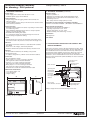
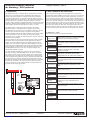
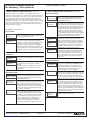
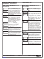
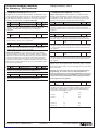
87045 LIMOGES Cedex France
Telephone: (+33) 05 55 06 87 87 - Fax: (+33) 05 55 06 88 88
BUS/KNX modular controller
for dimming - DALI protocol
Catalogue number(s): 0
026 35
CONTENTS
Page
1. Functions . . . . . . . . . . . . . . . . . . . . . . . . . . . . . . . . . . . . . . . . . . . 1
2. Technical features . . . . . . . . . . . . . . . . . . . . . . . . . . . . . . . . . . . . 2
3. Location and function of the control and
display elements . . . . . . . . . . . . . . . . . . . . . . . . . . . . . . . . . . . . . 2
4. Connection . . . . . . . . . . . . . . . . . . . . . . . . . . . . . . . . . . . . . . . . . 3
5. Menu operation and structure . . . . . . . . . . . . . . . . . . . . . . . . . . . 3
6. Commissioning . . . . . . . . . . . . . . . . . . . . . . . . . . . . . . . . . . . . . . 7
7. Communication objects . . . . . . . . . . . . . . . . . . . . . . . . . . . . . . . . 9
8. Parameters . . . . . . . . . . . . . . . . . . . . . . . . . . . . . . . . . . . . . . . . 11
9. Behaviour on voltage failure and recovery . . . . . . . . . . . . . . . . 14
1. FUNCTIONS
1. FUNCTIONS (continued)
The DALI modular controller combines the cross-functional KNX
installation bus and the DALI bus specifically designed for lighting
control.
1.2 Commissioning via embedded Web server
In addition to the KNX/DALI interface, the DALI modular controller also
has an RJ 45 interface which can be used to connect the device to an
existing IP network. The embedded Web server makes it very simple
to commission DALI using any Internet browser. The IP address,
programmed with ETS or allocated by a DHCP server, is entered
in a browser. It is also possible to access the Internet via a WLAN
connection. The commissioning site is designed so that it can be
displayed on a portable PDA. This allows the technician responsible
for commissioning to move freely around the device.
It is thus possible to integrate lamps equipped with light-duty digital
DALI ECGs in a global KNX architecture and control them from a
number of existing KNX devices.
The DALI modular controller acts as both DALI master interface and
power supply for a maximum of 64 connected ECGs.
The ECGs can be switched, attenuated or set with a value defined in a
maximum of 16 groups per gateway. The actual light value or the error
status of each group (error status of ECGs/lamps in each group) can
be exported, for example, to a display interface via a KNX gateway.
The DALI modular controller can be used not only to control the
group, but also to control up to 64 ECGs. In the latter case, there is
one object per ECG. A parameter determines if each ECG should be
switched, attenuated or set to a defined value.
An error status object is available for each ECG. This allows lamps
and ECGs with an anomaly to be located precisely. Three objects can
be used for total control of all the ECGs connected via Broadcast (no
DALI needs to be commissioned in this case).
Moreover, the device has binary inputs. It is possible to enable
functions directly using simple push-buttons connected to the device.
The push-button function is available without an existing KNX bus and
is particularly useful for the installation phase (operations performed
on site).
A modular device (6 modules), the DALI modular controller can be
mounted directly on a 35 mm DIN rail in standard sub-distribution.
The connection to the bus uses a standard bus coupler. DALI, the
power supply and the push-buttons are connected using screw-type
connectors.
The device can be controlled via the application program.
In addition, each group can be used to program and load up to
16 lighting scenes. Scenes are controlled by a 1-byte object.
Thanks to the DALI modular controller, it is possible to commission
the DALI (assignment of DALI ECGs to the various groups and
modification of the configuration) in two different ways.
1.1 Commissioning via the device
The DALI can be commissioned from the integrated screen
and programming buttons, without KNX and without prior ETS
programming. This method is particularly recommended when
the DALI is installed by an electrician and the ETS software is
programmed at a later date by a systems integrator.
Technical data sheet: S000064593EN-1
CONTENTS
Updated on:
Created on: 15/06/2012
1/14
BUS/KNX modular controller
for dimming - DALI protocol
Catalogue number(s): 0 0
26 35
2. TECHNICAL FEATURES
2. TECHNICAL FEATURES (continued)
Power supply
• Power supply 110 to 240 V, 50 to 60 Hz, 0.1 A max.
• Additional power supply via the KNX bus
Electrical safety
• Degree of pollution: 2
• Protection (in accordance with standard EN 60529): IP20
• Protection class: (in accordance with standard IEC 1140) I
• Overvoltage class: III
• Bus: Safety extra low voltage (SELV) 24 V DC
Control elements
• Programming button for toggling between normal mode and
addressing mode
• 3 buttons (MOVE, Prg/Set, ESC) on the front can be used to set the
device and the parameters
Conformity to electromagnetic compatibility standards
Conforms to standards EN 50081-1, EN 50082-2 and EN50090-2-2
Display elements
• Red LED indicating whether the device is operating in normal mode
or in addressing mode
• Green PWR LED indicating that the device is ready to operate
(flashes in normal operating mode)
• Red ERR LED indicating error status.
• 2 x 12-character display for navigating through the menus for
commissioning and parameter setting
Environmental specifications
• Resistance to the weather: EN 50090-2-2
• Operating temperature: 0°C to +45°C
• Storage temperature: -25°C to +70°C
• Relative humidity (non-condensing): 5 to 93%
Inputs
• Volt-free binary input, passive for connecting push-buttons or the
9-32 V DC or 8-26 V AC presence sensor, max. wire length: 15 m
CE certified
DALI bus
• Connection of 64 ECGs maximum, in accordance with standard
IEC 60926
• DALI 18-21 V DC voltage, short-circuit protection
• No other control device (master DALI devices) should be used
Ethernet
• IP connection via Ethernet, rate 10 Mbps, only used for
commissioning DALI
• IP address assignment by a DHCP service or fixed IP address
Connectors
• Bus line: KNX bus coupler
• Power supply: 3 x 1.5 mm² screw-type connector
with single-core cable or threaded conductor
• DALI bus: 3 x 1.5 mm² screw-type connector
with single-core cable or threaded conductor
• Binary input: 3 x 1.5 mm² screw-type connector
with single-core cable or threaded conductor
• Ethernet: RJ 45 socket for standard connection cable
Certification
KNX approved
3. L
OCATION AND FUNCTION OF THE CONTROL AND
DISPLAY ELEMENTS
The device connectors and the LED and programming button, which
are necessary elements for commissioning, are only accessible once
the switchboard cover has been lifted out of the way. However, the
programming buttons (MOVE, Prg/Set, ESC), which are necessary
elements for commissioning the DALI interface and setting the
parameters, can be enabled with the cover closed. The two-line menu
display and the control LEDs (PWR and ERR) can also be read with
the cover closed.
Connector passive
binary input 1
Connector passive
binary input 2
DALI connector
Operating LED
Mechanical characteristics
• Case: Plastic PA66 – V0
• Case dimensions:
• Weight : 200 g
MOVE button
Prg/Set button
ESC button
2 x 12-character display
for configuring the DALI
interface
86
106
Programming button
Programming LED
55
RJ 45 socket
for the Ethernet connection
Error LED
Always comply with the connector labelling on the case.
• Mounting: On 35 mm DIN rail
Technical data sheet: S000064593EN-1
CONTENTS
Updated on:
Created on: 15/06/2012
2/14
BUS/KNX modular controller
for dimming - DALI protocol
Catalogue number(s): 0 0
26 35
4. CONNECTION
5. MENU OPERATION AND STRUCTURE
The DaliControl SC64 is a modular device, designed to be mounted
directly on a 35 mm DIN rail in the switchboard. After clipping the
device on the rail, the DALI bus should be linked to the connector
in the top left-hand corner. In accordance with IEC 90929, the DALI
interface control wires can be part of a 5-wire cable which also powers
the ECGs (the basic insulation is adequate). However, each wire
should be clearly marked and identified precisely. The maximum wiring
length of a complete DALI installation on the same segment must not
exceed 300 m. (Recommended cable cross-section: 1.5 mm²).
The connected DALI segment can be switched on using the three
programming buttons (MOVE, Prg/Set, ESC) and the 2 x 12-character
display on the front of the device. The DALI parameters can then be
set or changed using these buttons and the display. Operation of this
device is controlled using menus. Depending on the current position in
the menus, up to two submenus can be accessed. The selected menu
element is displayed on screen. The user navigates around the menu
by pressing the buttons briefly. The Move button can be used to select
the next menu element on each level. The Prg/Set button can be
pressed quickly to select the submenu. The ESC button can be used
to exit the current menu level and return to the higher menu element.
The power supply is connected to the connector in the bottom
right‑hand corner, in accordance with the diagram on the device.
The KNX cable is connected using a standard bus connector, already
inserted in the unit when the device is supplied. A basic double
insulation adapted between the KNX installation and the power supply
must be provided. It is therefore necessary to sheath, using the
retractable sleeve supplied, the KNX control wires, from the end of the
cable to the bus connector.
Once the device has been connected and the power supply enabled,
the product name and the firmware version appear on the device
display. The green PWR LED flashes to indicate that the device is
ready to use. If the device is switched on without KNX, the red error
LED lights up. If the ERR LED remains lit after connecting the KNX,
there is probably a short-circuit in the DALI interface segments (see
SYSTEM TEST submenu). In this case, check the wiring on the
relevant DALI interface segment.
The DALI modular controller also makes it easy to commission a
Dali segment via the embedded Web server. To do this, the device
has an RJ 45 socket on top of the bus coupler, in the device bottom
right-hand corner. The device can be connected to a selector switch
or an IP network router (Ethernet) using a standard connection cable.
The connection is usually only required for commissioning and can
therefore be temporary. Once the commissioning process is complete,
the Ethernet connection is no longer necessary. When the power
supply is connected, ensure sufficient distance is kept between the
IP cable and the power supply cable.
5.1 Main menu – Level 1
The main menu (level 1) is structured as follows:
DALI Control
SC64IP,V.2.1
The product name and the firmware version are
displayed. This screen has a submenu which can
be used to select the display language.
IP
ADDRESS
This submenu displays the IP address assigned
by the DHCP server or defined in the ETS
software.
NEW
INSTALLATION
POSTINSTALLATION
GROUP
ASSIGNMENT
In the submenus in this screen, the user can
assign the detected ECGs to the DALI groups of
his choice.
GROUP
PARAMETERS
The submenus in this screen can be used to
define and change the parameters in each
group.
SCENE
ASSIGNMENT
DALI
ECG
x 64
max.
BUS (RJ 45)
Ethernet
This submenu can be used to switch the whole
installation (Broadcast) and each of the channels
for test purposes.
TEST
SCENES
This submenu can be used to invoke the
programmed scenes individually for test
purposes.
FUNCTION
INPUT B1
FUNCTION
INPUT B2
Technical data sheet: S000064593EN-1
CONTENTS
Updated on:
In these submenus, the user can assign the
groups to DALI scenes.
GROUP
TEST
SYSTEM
TEST
KNX
This submenu can be used to reset all the
connected DALI devices and launches automatic
detection of the ECGs when a new DALI
segment is installed.
This submenu can be used to detect and
automatically synchronize the DALI ECG
configuration once these have been installed.
This submenu displays all the existing system
errors one by one.
In the submenus in this screen, it is possible to
define the function of binary input B1.
--- Same as above ---
Created on: 15/06/2012
3/14
BUS/KNX modular controller
for dimming - DALI protocol
Catalogue number(s): 0 0
26 35
5. MENU OPERATION AND STRUCTURE (continued)
5. MENU OPERATION AND STRUCTURE (continued)
If a function needs to be enabled or if a parameter needs to be
changed in a given submenu, it is necessary to switch to programming
mode at the selected point. To do this, press the Prg/Set button and
hold it down for at least 2 seconds. Once the selected function is
in programming mode, the → symbol appears on the screen. Once
programming mode has been enabled, use the Move button to modify
the setting or the parameter. The Prg/Set button can be pressed
briefly to end the procedure. The updated parameter is saved or the
selected function is enabled.
POST-INSTALLATION
POSTINSTALLATION
SEARCH ECG
via P-MODE
5.2 Submenu – Level 2 and 3
DALI CONTROL
DALI Control
SC64IP,V.2.1
LANGUAGE
FRENCH
The DALI CONTROL main menu is used to
access the LANGUAGES submenu. To do this,
press the Prg/Set button briefly.
The currently selected language is displayed in
the submenu. Enable programming mode by
pressing the Prg/Set button and holding it down
for at least 2 seconds. Use the Move button
to browse the available languages: GERMAN,
ENGLISH, FRENCH, SPANISH, SWEDISH. The
Prg/Set button can be pressed briefly to enable
the new language and change the display as a
result.
Detected
ECGs : 3
New
ECGs: 1
DEL./NEW
ECGs: 3/1
IP ADDRESS
IP
ADDRESS
IP: 192.
168.004.101
The Prg/Set button can be pressed briefly to
change from the IP ADDRESS main menu to the
submenu.
This submenu displays the IP address assigned
by the DHCP server or defined in the ETS
software.
This setting cannot be modified on the device.
This is done in the ETS software or via the
DHCP server.
NEW
INSTALLATION
SEARCH ECG
via P-MODE
Detected
ECGs: 47
The Prg/Set button can be pressed briefly to
change from the NEW INSTALLATION main
menu to the SEARCH ECG submenu via the
PROGRAMMING mode.
Pressing and holding down the Prg/Set button
sets the device to programming mode. Pressing
again, briefly this time, launches the reset and
search procedure. Initially, all the new ECGs
connected to the DALI segment are automatically
reset and the previous group parameters and
assignments are deleted.
The connected ECGs are searched for using
their long randomly-generated address and
are automatically identified in ascending order.
Depending on the number of ECGs connected,
the search process can take several minutes.
Once the search process is complete, the
number of deleted ECGs is displayed on the
screen. Press the ESC button (or wait 30
seconds) to go back to the higher menu level.
Technical data sheet: S000064593EN-1
CONTENTS
GROUP ASSIGNMENT
GROUP
ASSIGNMENT
ECGs Nr.: 12
NEW INSTALLATION
Updated on:
The Prg/Set button can be pressed briefly to
change from the POST-INSTALLATION main
menu to the SEARCH ECG submenu via the
PROGRAMMING mode.
Pressing and holding down the Prg/Set button
sets the device to programming mode. Pressing
again, briefly this time, launches the verification
and search procedure. The connected ECGs are
searched for using their long address. The result
is compared with the previous configuration. If
any ECGs have been removed from the DALI
segment, the corresponding inputs and settings
are automatically deleted from the DALI gateway.
During the verification process, the number of
deleted ECGs is displayed on the screen
The gateway then searches for new ECGs
connected to the DALI segment. The new
ECGs are automatically reset and the previous
group parameters and assignments are deleted.
Depending on the number of ECGs connected,
the search process can take several minutes.
During the verification process, the number of
deleted ECGs is displayed on the screen
Once the whole process is complete (verification
and search), the number of deleted ECGs and
the number of new ECGs are displayed on the
screen (deleted ECGs/new ECGs from left to
right, see image on left). Press the ESC button
(or wait 30 seconds) to go back to the higher
menu level.
ECGs Nr.: 12
GROUP: 1
ECGs Nr.: 12
GROUP: 1
The Prg/Set button can be pressed briefly to
change from the GROUP ASSIGNMENT main
menu to the submenu. In the submenu, the
ECGs detected during the search process can
be assigned to the 16 DALI groups and the
existing assignments can be modified
To navigate from one ECG to another in the
submenu, press the Move button briefly. The first
line of the screen indicates the number of ECGs
selected. The corresponding lamp will flash as
long as its ECG is selected. This makes it easy
to identify the number assigned to each lamp.
Pressing and holding down the Prg/Set button
sets the device to programming mode. Define
the group to which the ECG should be assigned
by pressing the Move button briefly. Once the
group has been selected, confirm and save the
setting by pressing the Prg/Set button briefly. In
the case of a new installation, this task should be
performed once for each of the ECGs detected
during the search process.
Press the ESC button (or wait 30 seconds) to go
back to the higher menu level.
Created on: 15/06/2012
4/14
BUS/KNX modular controller
for dimming - DALI protocol
Catalogue number(s): 0 0
26 35
5. MENU OPERATION AND STRUCTURE (continued)
5. MENU OPERATION AND STRUCTURE (continued)
GROUP PARAMETERS
SCENE ASSIGNMENT
GROUP
PARAMETERS
GROUP: 01
PARAMETERS
GROUP: 01
PARAMETERS
GROUP: 12
ON-VALUE: 100
GROUP: 12
MIN VAL: 0
GROUP: 12
MAX VAL: 100
GROUP: 12
DURATION: 10s
The Prg/Set button can be pressed briefly to go
from the GROUP PARAMETERS main menu
to the submenu. In this menu, it is possible to
set the various parameters in each group. As a
general rule, the group parameters must be set
in the ETS software when commissioning the
KNX bus. The parameters should only be set
directly on the device when quickly changing
individual parameters. Caution: Whenever ETS is
downloaded, it deletes all the manual parameter
settings in the device!
To scroll through the various groups, press
the Move button briefly. The first line of the
screen indicates the group currently selected.
Pressing and holding down the Prg/Set button
sets the device to programming mode. The
parameter type and its value are then displayed
on the second line of the screen. The following
parameters can be modified directly on the
device:
• Initial (ON) value: 0 to 100%
in steps of 5%
• Minimum dimming value: 0 to 40%
in steps of 5%
• Maximum dimming value: 50 to 100%
in steps of 5%
• Dimming time for dimming from
0 to 100%: 5 to 60 s.
In programming mode, the selected parameter
can be modified by pressing the Move button
briefly. Pressing the Prg/Set button briefly saves
the setting value and, at the same time, enables
programming mode automatically for the next
group parameter.
This means that, for example, only the maximum
dimming value parameter needs to be modified,
the user should first enter the initial value and
the minimum dimming value (level 2 menu).
Press the ESC button (or wait 30 seconds) to go
back to the higher menu level.
SCENE
ASSIGNMENT
SCENE01 XXX
XXXXXXXXXX
SCENE03 −−−
XXXX−−−−XX
SCENE03 −−−
XXXX−−−−XX
GROUP TEST
GROUP
TEST
GROUP: 6
TEST
GROUP: 6
—>off
Technical data sheet: S000064593EN-1
CONTENTS
Updated on:
The Prg/Set button can be pressed briefly to go
from the SCENE ASSIGNMENT main menu to
the submenu. In this menu, the DALI groups
can be assigned to a maximum of 16 different
scenes
To navigate from one scene to another, press
the Move button briefly. The first line of the
screen indicates the number of the scene
currently selected. Symbols indicate which of the
16 groups is assigned to this scene. An "X" in
the corresponding place means that the group
is assigned to the scene. The – symbol means
that the group has not been assigned. The four
characters following the scene number on the
first line represent, from left to right, groups 1 to
4. The 12 characters on the second line of the
screen correspond, in ascending order from left
to right, to groups 5 to 16.
Pressing and holding down the Prg/Set button
sets the device to programming mode. A flashing
cursor on the first X indicates that Group 1 is
currently selected. By pressing the Move button
briefly, the user can choose whether or not to
assign this group to the selected scene (toggle
between symbols X and -). To move the cursor
to the next Group, press the Prg/Set button
briefly. Once you have gone through all 16
groups, the configuration is saved and taken into
account as soon as the scene is reprogrammed.
Press the Prg/Set button to go back to the higher
menu level automatically. Press the ESC button
(or wait 30 seconds) to go back to the higher
menu level without saving the changes made.
The Prg/Set button can be pressed briefly
to go from the GROUP TEST main menu to
the submenu, which allows all the groups to
be switched individually or collectively (ALL
CHANNELS: Broadcast) in order to test the
installation
To go from one channel to another, press the
Move button briefly. The active channel number
appears on the first line of the display
Pressing and holding down the Prg/Set button
sets the device in programming mode. To
choose whether the selected channel should be
enabled or not, press the Move button briefly. To
perform the selected operation, press the Prg/
Set button briefly. Press the ESC button (or wait
30 seconds) to go back to the higher menu level.
Created on: 15/06/2012
5/14
BUS/KNX modular controller
for dimming - DALI protocol
Catalogue number(s): 0 0
26 35
5. MENU OPERATION AND STRUCTURE (continued)
5. MENU OPERATION AND STRUCTURE (continued)
TEST SCENES
FUNCTION INPUT B1
TEST
SCENES
SCENE: 2
TEST
SCENE: 2
—>invoke
The Prg/Set button can be pressed briefly to
go from the TEST SCENES main menu to the
submenu. In this submenu, it is possible to
invoke all the scenes for test purposes or assign
the recently-defined lighting scenarios to the
corresponding scene.
To go from one scene to another, press the
Move button briefly. The number of the currently
selected scene appears on the first line of the
display.
Pressing and holding down the Prg/Set button
sets the device to programming mode. To go
from the Invoke a scene function to the Save a
scene function, press the Move button briefly.
To perform the selected operation (invoke a
scene or save a scene), press the Prg/Set
button briefly. Press the ESC button (or wait
30 seconds) to go back to the higher menu level.
FUNCTION
INPUT B1
TOG/DIM
INPUT B1
TOG/DIM
GROUP: ALL
SCENE: 2
—>invoke
SYSTEM TEST
SYSTEM
TEST
SYSTEM
NO ERROR
SYSTEM
DALI ERROR
SYSTEM
L. -ERROR: 23
SYSTEM
ECG-ERROR:34
SYSTEM
KNX ERROR
The Prg/Set button can be pressed briefly to
go from the SYSTEM TEST main menu to the
submenu. This menu is used to display any error
messages
If there is no error, this is also indicated on the
display. The following errors, which result in the
red error LED lighting up, can be detected by the
system and displayed on the screen:
• Short-circuit on the DALI
• Error on a lamp with display of the relevant
lamp or ECG number
• Error on an ECG with display of the relevant
ECG number
• No KNX bus
In the event of a short-circuit on the DALI, no
other error can be detected. For other types
of error, it is possible to detect several errors
simultaneously. To go from one error to another,
press the Move button briefly. In the event of an
error on a lamp or an ECG, the relevant ECG
number is displayed so the error can immediately
be located in the group. Press the ESC button
(or wait 30 seconds) to go back to the higher
menu level.
Technical data sheet: S000064593EN-1
CONTENTS
Updated on:
TOG/DIM
CHANNEL: 07
The Prg/Set button can be pressed briefly to
go from the FUNCTION INPUT B1 main menu
to the submenu. This submenu can be used to
define the function of the volt-free push-button
connected to binary input B1
To go from one available function to another,
press the Move button briefly. The number of the
currently selected function appears on the first
line of the display. The following functions can
be set:
• ON: The function is enabled by pressing the
push-button.
• OFF: The function is disabled by pressing the
push-button.
• TOGGLE: Switches between On and Off when
the push-button is pressed.
• ON/DIM: Push-button pressed briefly: lights
up; push-button pressed and held
down: increasing dimming with stop
telegram.
• OFF/DIM: Push-button pressed briefly: goes
off; push-button pressed and held
down: gradual decrease with stop
telegram.
• TOG/DIM: Push-button pressed briefly:
switches between On and Off;
push‑button pressed and held down:
dimming by simply holding down the
button.
• SCENE: A scene is invoked by pressing the
push-button.
Pressing and holding down the Prg/Set button
sets the device to programming mode. To
choose the scene or the channel to which the
selected function will be connected, press the
Move button briefly. Press the ESC button (or
wait 30 seconds) to go back to the higher menu
level.
Created on: 15/06/2012
6/14
BUS/KNX modular controller
for dimming - DALI protocol
Catalogue number(s): 0 0
26 35
5. MENU OPERATION AND STRUCTURE (continued)
6. COMMISSIONING (continued)
FUNCTION INPUT B2
6.1 Commissioning DALI using buttons and the
device screen (continued)
If push-buttons are connected to the device inputs, use the
FUNCTION INPUT B1 and B2 menus to define the push-button
function and assign the inputs to the various DALI groups. This allows
the DALI functions to be executed (operations performed on site) even
before the KNX is up and running. In addition, the binary inputs can
also be used in normal operating mode to integrate standard light-duty
push-buttons or presence sensors in the system.
FUNCTION
INPUT B2
TOG/DIM
INPUT B2
TOG/DIM
GROUP: ALL
SCENE: 2
—>invoke
The Prg/Set button can be pressed briefly to
go from the FUNCTION INPUT B2 main menu
to the submenu. This submenu can be used to
define the function of the volt-free push-button
connected to binary input B2.
To go from one available function to another,
press the Move button briefly. The number of the
currently selected function appears on the first
line of the display. The following functions can
be set:
• ON: The function is enabled by pressing the
push-button.
• OFF: The function is disabled by pressing the
push-button.
• TOGGLE: Switches between On and Off when
the push-button is pressed.
• ON/DIM: Push-button pressed briefly: lights
up; push-button pressed and held
down: increasing dimming with stop
telegram.
• OFF/DIM: Push-button pressed briefly: goes
off; push-button pressed and held
down: gradual decrease with stop
telegram.
• TOG/DIM: Push-button pressed briefly:
switches between On and Off;
push‑button pressed and held down:
dimming by simply holding down the
button.
• SCENE: A scene is invoked by pressing the
push-button.
Pressing and holding down the Prg/Set button
sets the device to programming mode. To
choose the scene or the channel to which the
selected function will be connected, press the
Move button briefly. Press the ESC button (or
wait 30 seconds) to go back to the higher menu
level.
Finally, groups can be assigned to the various scenes using the
SCENE ASSIGNMENT menu (see menu operation and structure
above).
Commissioning the DALI segment is then complete.
Commissioning the KNX parameter setting can be started immediately
or later using the ETS software and the corresponding application
program.
x 64
KNX
power
supply
035 12
KNX/DALI
controller
**
ETS software
035 43
**
026 35
OR
035 47
b USB
**
ETS software
SCS OFFER
Control units and detectors in
the SCS offer
6. COMMISSIONING
Assign the devices detected to the various DALI groups using the
GROUP ASSIGNMENT menu (see menu operation and structure
above). The basic installation is complete when all the ECGs have
been assigned to the desired groups.
a RJ 45
Manual
SCS*
power
supply
6.1 C
ommissioning DALI using buttons and the
device screen
Once the device has been wired up in accordance with the above
instructions, the DALI line can be commissioned. This operation can
be performed independently of commissioning the KNX bus. While
KNX is not connected, the red error LED lights up to indicate an error.
DALI can still be commissioned, however. For the initial installation,
start by finding the DALI line for all the connected ECGs using the
NEW INSTALLATION menu (see menu structure described above).
Once all the connected devices have been detected (indicated by
(ESC) behind the number of devices detected indicated on screen),
quit this menu element.
Configuration option **
KNX OFFER
035 67
KNX/SCS
interface
026 34
*SCS power supply Cat. No. 035 67 supplied with Cat. No. 026 34 (KNX/SCS
interface)
**Option of configuring the KNX/DALI controller directly via the RJ 45
connection (requires use of a software program... supplied with the commonly
used product)
a b: product software configuration possible via
a: IP using the IP communication module Cat. No. 0 035 43
b: USB using the BUS/KNX interface - USB Cat. No. 0 035 47
Using the GROUP TEST menu (see menu operation and structure
above), each of the groups can be enabled or disabled for test
purposes.
Technical data sheet: S000064593EN-1
CONTENTS
Updated on:
Created on: 15/06/2012
7/14
BUS/KNX modular controller
for dimming - DALI protocol
Catalogue number(s): 0 0
26 35
6. COMMISSIONING (continued)
6. COMMISSIONING (continued)
6.2 Commissioning DALI via the Web server
DALI can also be commissioned easily via a Web server embedded
in the device. The DaliControl SC64Ip can be connected directly to
the IP network for this purpose. An RJ 45 socket is located above the
KNX bus connector, on the bottom left-hand side of the device. The
device can be connected to a selector switch, a hub or an IP network
router using a standard connection cable. As the network connection
is only needed for the commissioning process, a temporary connection
is usually sufficient. Once the process is complete, the network
connection can be disabled. It is, of course, also possible to use a
Wi-Fi access point as a network coupler. In this case, commissioning
can be performed using a laptop, a PDA or any other control device.
6.2 Commissioning DALI via the Web server (suite)
Once connected to the network, load the commissioning website
into a web browser (Microsoft Internet Explorer or Mozilla Firefox, for
example). Enter the IP address (URL) assigned by the DHCP server
or set in the ETS for this purpose, in the browser.
Note: The full URL is made up of the IP address preceded by the
prefix http://.
Thus, for example, you need to enter http://192.168.101 in the
browser to access the page.
As can be seen in the figure below, the website will then appear in the
browser.
The fields under the toolbar are used to identify ECGs and assign
groups. To identify the ECGs, the Broadcast function should first of all
be used to set all the lamps to a defined value (OFF, for example).
After selecting the toggle
button, the ECGs can be switched on
or off individually with just a click of the mouse. ECGs arranged in
random order can thus be identified.
Once the ECGs have been identified, each of them can be assigned
to groups. Start by selecting the Assignment
button. Select the
group to which the ECG should be assigned by clicking the mouse.
Click on the ECG again to assign it to the selected group. A blue field
containing the group number appears in the list of ECGs to indicate
that the ECG has been assigned to the group. ECGs which have not
yet been assigned to a group are followed by a yellow field containing
a question mark.
The ECG position (long address) in the DALI segment is usually
random. During a new installation, the addresses are detected and
assigned automatically to a short address 0..63. The ECGs are
added to the list randomly. If an ECG needs to be placed in a specific
position in the list (special short address), its position can be changed
using the Reverse
button. To change an ECG's position, press
the Reverse button, then click on both devices which you wish to swap
position.
In addition to identification and assignment to groups, a different web
site is used to set the scene values and assign scenes. To access the
scene page from the commissioning page, use the
button. The
page looks like this:
To set a scene, first select the right-hand side. Once selected, the
A toolbar at the top of the Web page provides access to the main
commissioning functions. The various ICONS displayed in the toolbar
have the following meanings and functions:
Update
New
installation
Postinstallation
Cancel
Broadcast
enabled
This function is used to update the displayed
ECG assignments. It should mainly be used
when assignments have been modified
manually on the device or using the software.
This button is used to start a new installation
of the connected DALI segment. Warning: If a
new installation is launched, any pre-existing
configuration in the DALI segment will be
deleted.
This button is used to start post-installation of
the connected DALI segment, by deleting any
ECG which would no longer exist and adding
any new devices.
Pressing this button stops all the current
processes.
Using a DALI Broadcast telegram, all ECGs/
lamps on the DALI segment can be switched
on or off simultaneously.
Broadcast
disabled
Display a
scene page
Using this button, the user can display a scene
setting page.
Technical data sheet: S000064593EN-1
CONTENTS
Updated on:
scene (if it already exists) will be loaded into the DALI segment. The
currently defined light values are displayed in the corresponding
group window. The buttons can be used to modify the light values
individually. To do this, select one of the following buttons:
(On, Off, + Dimming, - Dimming).
A short (switching) or long (dimming) click of the mouse button on the
corresponding group window can modify the light value for the whole
group. Press the
button.
The Back
button allows you to return to the previous page.
Created on: 15/06/2012
8/14
BUS/KNX modular controller
for dimming - DALI protocol
Catalogue number(s): 0 0
26 35
7. COMMUNICATION OBJECTS
7. COMMUNICATION OBJECTS (continued)
A maximum of 252 communication objects allow the device to
communicate via KNX. The objects are displayed or hidden according
to how the parameters are set. Communication objects can be
connected to 255 group addresses via 255 associations.
The DALI modular controller can also be used to control each of the
64 ECGs/lamps individually. However, in this case, there is only one
object available per ECG. The type of control and, as a result, the
object type can be defined by a specially-designed parameter (see
below). Each ECG/lamp is controlled by objects 112 to 175.
5 objects are assigned to each of the DALI 16 groups.
The objects in group 1 are:
Obj. Function
Object name
Type
Flag
0
On/Off
Switch, group 1
1-bit
CWT
This object is used to switch the lamps assigned to DALI group 1
according to the value attributed to it (ON or OFF). It is possible
to determine in the parameters whether switching should happen
immediately or whether the final switching value should be reached
by dimming on receipt of the object. The dimming time can be set
independently of the time needed to receive a dimming telegram.
1
Lighter/
Dimming, group 1
4-bit
CWT
Darker
This object is used to modify the light intensity of lamps assigned to
DALI group 1. The time needed to go from zero dimming to 100%
dimming can be set in the parameters.
2
Value
Value, group 1
1-byte CWT
lamps assigned to DALI group 1 are set to a given level of light value
by means of this object. It is possible to determine in the parameters
whether the value should be accepted immediately or whether the
final value should be reached by dimming on receipt of the object.
The dimming time can be set independently of the time needed to
receive a dimming telegram.
Obj. Function
Object name
Type
Flag
112 On/Off
Switch, ECG 1
1-bit
CWT
Value
Dimming, ECG 1
4-bit
CWT
Lighter/
Setting value, ECG 1
1-byte CWT
Darker
This object is used to apply switching, dimming or to define a light
value (according to the parameters) on the lamp controlled by
ECG 1, individually and independently of the group it belongs to.
Warning: An inconsistency can occur between the actual lamp
light value and the group status value when individual control of
ECGs and their assignment to a group are used simultaneously.
As a result, when using individual controls, we recommend that
you don't assign the corresponding ECG to a group or use it
via group controls. This is the only way to be sure of avoiding
incorrect status reports.
In the same way as object 112 is assigned to ECG 1, objects 113 to
175 are used for ECGs 2 to 64.
The DALI modular controller offers the possibility of making the error
status of each connected ECG available via a KNX communication
object. Objects 176 to 239 are used for this purpose.
On/Off
Status, group 1
1-bit
CRT
Value
Status, group 1
1-byte CRT
The status of lamps assigned to DALI group 1 can be accessed
by means of this object. If a 1-bit status (On/Off) or a status with a
value of 1 byte (0…100%) is sent, it can be set in the parameters.
The object type changes according to the parameter settings. The
obligation to send the object can be set.
Object name
Type
Flag
Error status,
1-bit
CRT
ECG 1
1-byte CRT
This object is used to inform the user of the error status of ECG 1.
It is possible to determine in the parameters whether the object is
defined for a malfunctioning lamp, a malfunctioning ECG or both
types of malfunction. If an error has occurred, the 1-bit object has
the value 1, if no error has occurred, it has value 0. An error status
can also be configured as a 1-byte object. In this case, the object
values are as follows:
Warning: When parameters are set as value states, the value is
sent as soon it is modified during the dimming process. This
results in an extra load on the bus during dimming.
No error:
lamp error:
ECG error:
3
4
Failure
Error status, group 1
1-bit
CRT
This object is used to inform the user of an error status within a DALI
group. It is possible to set in the parameters the sending of an error
status in the event of a malfunctioning lamp, a malfunctioning ECG
or both types of malfunction. An object value of 0 means that no
error has occurred in the group. A value of 1 means that at least one
error has been detected within the group. The obligation to send the
object can be set.
Obj. Function
176 Failure
0
1
2
In the same way asobject 176 is assigned to ECG 1, objects 177 to
239 are used for ECGs 2 to 64.
In the same way as objects 0 to 4 assigned to DALI group 1, objects
7 to 11 are assigned to DALI group 2, objects 14 to 18 to group 3,
etc., up to objects 105 to 109 assigned to DALI group 16.
Technical data sheet: S000064593EN-1
CONTENTS
Updated on:
Created on: 15/06/2012
9/14
BUS/KNX modular controller
for dimming - DALI protocol
Catalogue number(s): 0 0
26 35
7. COMMUNICATION OBJECTS (continued)
7. COMMUNICATION OBJECTS (continued)
In addition to the group and individual controls, the application can be
used to control all the ECGs. In this case, communication is provided
by DALI Broadcast telegrams and there is no need for a new DALI
installation. For total control, use objects 240 to 242.
Objects 245 to 248 are used to inform the user about the status
of errors on the whole DALI segment. Objects are sent each time
a modification is made. However, they can also be requested. The
following error objects are available for the whole segment:
Obj. Function
Object name
Type
Flag
240 On/Off
Switching, Broadcast
1-bit
CWT
This object is used to switch all the lamps connected to the DALI
segment to the value ON or OFF defined using DALI Broadcast
telegrams. For Broadcast switching, always use the group 1
parameters.
Obj. Function
Object name
Type
Flag
245 Error
Error status, all errors
1-bit
CRT
This object is used to inform the user of the error status on the Dali
segment, regardless of the type of error. Value 0 means that no
error has occurred. Value 1 means that an error has occurred on the
segment.
241
246 Error
Error status, DALI bus
1-bit
CRT
This object is used to inform the user of an error status generated
by a short-circuit on the DALI. Value 0 means that no error has
occurred. Value 1 means that a short-circuit has occurred on DALI.
247 Error
Error status, general lamp
1-bit
CRT
error
This object is used to inform the user of the error status of lamps on
the DALI segment. Value 0 means that no error has occurred. Value
1 means that an error has occurred in at least one of the lamps on
the segment.
Lighter/
Dimming, Broadcast
4-bit
CWT
Darker
This object is used to modify the light intensity of all lamps
connected to DALI using DALI Broadcast telegrams. For Broadcast
dimming, always use the group 1 parameters.
242 Value
Value, group 1
1-byte CWT
This object is used to set all the lamps connected to DALI to a
light value given using DALI Broadcast telegrams. For Broadcast
switching, always use the group 1 parameters.
Objects 243 and 244 are used to make the volt-free push-button
signal also available on the KNX. The push-button function is defined
directly on the device via the operating menu (see Assembly and user
manual). Don't forget that even when the push-button is configured
as a dimming button for the DALI groups, only the switching object
(short press on the button) is available for the KNX. If the push-button
parameters are set to invoke a DALI scene, the corresponding object
does not have any function.
Obj. Function
Object name
Type
Flag
243 On/Off
Switching, input 1
1-bit
CRWT
This object issues a switching signal which depends on the function
defined for the push-button connected to volt-free input 1.
244 On/Off
Switching, input 2
1-bit
CRWT
This object issues a switching signal which depends on the function
defined for the push-button connected to volt-free input 2.
248
Error
Error status, general ECG
1-bit
CRT
error
This object is used to inform the user of the error status of ECGs on
the DALI segment. Value 0 means that no error has occurred. Value
1 means that an error has occurred in at least one of the ECGs on
the segment.
Object 252 is needed to program and invoke previously-defined
lighting scenes. Don't forget that each of the DALI groups is assigned
to the various device scenes using the operating menu (see Assembly
and user manual).
Warning: The scene light values are saved in the ECGs during
programming. As a result, make sure that all the ECGs are
connected and ready for use during programming. If a scene has
been programmed and the required ECG is not connected, there
may be inconsistency between the actual setting value and the
status signalled by the gateway.
Obj. Function
Object name
Type
Flag
252 Invoke/save
Scenes 1 to 16
1-byte CW
scenes
This object is used to invoke scenes 1 to 16 on receipt of a telegram
containing values 0 to 15. If the highest significant bit has also been
defined (on a value between 128 and 143), the defined lighting is
saved in the corresponding scene.
Invoke
Save
Scene 1
0
128
Scene 2
1
129
Scene 3
2
130
...
Scene 14
13
141
Scene 15
14
142
Scene 16
15
143
Technical data sheet: S000064593EN-1
CONTENTS
Updated on:
Created on: 15/06/2012
10/14
BUS/KNX modular controller
for dimming - DALI protocol
Catalogue number(s): 0 0
26 35
8. PARAMETERS
8. PARAMETERS (continued)
For greater clarity, the parameters are spread out over several pages.
The available parameters are as follows:
8.1 General page
Parameter
Settings
Sending condition of status
Sending on demand only
object
Sending on change
This parameter is used to define the sending condition of a lamp
status in the DALI groups (4th communication object in each group).
Behaviour on KNX bus voltage No change
failure
Change to failure value
Switch off
This parameter is used to determine the lighting conditions to be
applied if there is a KNX bus voltage failure.
Behaviour on KNX bus voltage No change
recovery
Change to last value
Change to failure value
Switch off
This parameter determines the lighting conditions to be applied when
there is a KNX bus voltage recovery.
Behaviour on recovery after
DALI failure
No change
Change to last value
Switch off
This parameter is used to determine the lighting condition to be
applied after a DALI error (ECG short-circuit or error).
Sending condition failure
Sending on demand only
object
Sending on change
This parameter is used to define the sending condition of an error
status in the DALI groups (5th communication object in each group).
All the error statistics (objects 245 to 248) are still sent if there is a
change.
Light value on DALI and KNX
failure
No change
0%
5%
10%
.... (etc., in increments of 5%)
90%
95%
100%
Adjustment in groups
This determines the light value to be applied if there is an error on
the DALI or KNX. If the "Adjustment in groups" parameter is enabled,
two extra pages appear and allow the user to select the error values
in each group individually.
Start of DALI new and postEnabled
installation by push-buttons:
Disabled
This parameter is used to determine whether a new installation
or additional installation of the DALI can be performed using the
device push-buttons. It is thus possible to protect the device against
unauthorised access.
You will find a page for each group which allows you to set the
specific group parameters.
Technical data sheet: S000064593EN-1
CONTENTS
Updated on:
Created on: 15/06/2012
11/14
BUS/KNX modular controller
for dimming - DALI protocol
Catalogue number(s): 0 0
26 35
8. PARAMETERS (continued)
8. PARAMETERS (continued)
8.2 Group 1 - 16 page
Parameter
Maximum value for dimming
Settings
50%
55%
60%
.... (etc., in increments of 5%)
90%
95%
100%
Defines the maximum dimming value.
Accept value immediately
Dimming to the defined value
This parameter is used to determine whether the switch-on value
needs to change directly to the defined switch-on value or should
gradually increase to this value on receipt of a telegram 1.
Behavior when receiving On
Accept value immediately
Dimming to the defined value
This parameter determines whether the switch-off value needs to
change directly to the defined switch-off value or should gradually
decrease to this value on receipt of a telegram 0.
Behavior when receiving Off
Parameter
Switch on value:
Settings
0%
5%
10%
.... (etc., in increments of 5%)
90%
95%
100%
Last value
This parameter is used to define the light value which should be set
in the corresponding DALI group on receipt of a telegram 1.
If the "last value" setting has been selected, the switching value on
receipt of a telegram 1 is the value defined in the dimming setting or
the value before receipt of telegram 0.
Dimming time
2.5 seconds
5 seconds
10 seconds
15 seconds
20 seconds
30 seconds
1 minute
…..
30 minutes
1 hour
This parameter is used to define the time needed to go from 0%
lighting to 100% lighting on receipt of a dimming telegram (dimming
speed).
Minimum value for dimming
0%
5%
10%
15%
20%
25%
30%
Defines the minimum dimming value. The 0% setting means that the
dimmer can also be used to switch off the light. It is always possible
to switch off the light using the dimmer.
Technical data sheet: S000064593EN-1
CONTENTS
Updated on:
Behavior when receiving value Accept value immediately
Dimming to the defined value
This parameter is used to determine whether the light value needs
to change directly to the defined light value or should gradually
increase or decrease to this value on receipt of a 1-byte telegram.
Dimming time for "On", "Off",
"Set value"
2.5 seconds
5 seconds
10 seconds
15 seconds
20 seconds
30 seconds
1 minute
…..
30 minutes
1 hour
This parameter is used to set the time needed for dimming from 0
to 100% on receipt of a "On", "Off" or "Set value" telegram if this
parameter has been set to "Dimming to the defined value".
Switch status, 1 bit
Value status, from 0 to 100%
This parameter is used to determine whether the status object
needs to make the ON/OFF switching status available for just the
corresponding DALI group or whether it should also make the
0…100% value status available.
Type of status object
Type of recognized failures
No error status
Lamp error only
ECG error only
ECG and lamp error
This parameter is used to determine the error types for which the
error object in each group makes an error status available.
If, in the General Parameters page, the "Light value on DALI and KNX
failure" parameter is set to "Adjustment in groups", two extra pages
appear and allow the user to select the error values individually.
Created on: 15/06/2012
12/14
BUS/KNX modular controller
for dimming - DALI protocol
Catalogue number(s): 0 0
26 35
8. PARAMETERS (continued)
8. PARAMETERS (continued)
8.3 Failure value group 1 to 8 page
Parameter
ECG individual control
Settings
No
Yes
The user can define here whether or not the ECGs should be
controlled individually. If the "Yes" parameter is selected, additional
parameters will appear so that the user can set the various controls.
No individual control
Switching via a 1-bit object only
.....
Dimming via a 4-bit object only
Setting the value via a 1-byte object
ECG 64
only
This parameter allows the user to determine the type of object to use
for individual ECG control. A single object is available for each ECG
in this case. The type of object appears according to the parameter.
ECG 1
Parameter
Value group 1:
Settings
No change
0%
...
5%
10%
Value group 8:
.... (etc., in increments of 5%)
90%
95%
100%
This parameter allows the user to define the light value to be applied
in the corresponding group if there is an error on the DALI or KNX.
In addition to the group and individual controls, the application can
also be used to control all the connected ECGs simultaneously. In this
case, communication is provided by DALI Broadcast telegrams and
there is no need for a new DALI installation.
8.5 Common control page:
The purpose of the "Error value group 9 to 16" page is similar to that
described on the previous page.
In addition to the group controls, the DALI modular controller can also
be used to control the ECGs individually. Enabling individual controls
and the type of individual control can be defined on a separate page.
8.4 ECG individual control page
Parameter
Settings
Common control by DALI
No
broadcast feasible:
Yes
This parameter allows the user to determine whether complete
control of all ECGs is possible. If the answer is yes, the group 1
parameters (dimming time, max. dimming value, etc.) are applied to
all ECGs.
Warning: In the event of total control via DALI Broadcast, the
group 1 parameters are applied (switch-on value, dimming time,
etc.). They can be set on the corresponding parameters page.
The DALI modular controller can also be used to commission a DALI
via a temporary or permanent IP network. Operations required for
the commissioning process can be performed via the Web pages in
the embedded Web server. The IP address is usually assigned by
the DHCP service of a network DHCP server. If no DHCP server is
available, the settings must be entered manually.
The required network configurations are defined using parameters.
Technical data sheet: S000064593EN-1
CONTENTS
Updated on:
Created on: 15/06/2012
13/14
BUS/KNX modular controller
for dimming - DALI protocol
Catalogue number(s): 0 0
26 35
8. PARAMETERS (continued)
9. B
EHAVIOUR ON VOLTAGE FAILURE AND RECOVERY
8.6 IP configuration page
The various scenarios in the event of voltage failure and recovery can
be set via the parameters on the General parameters page.
The behaviour of connected lamps can be set via the "Behavior on
KNX bus voltage failure and recovery" parameters. If the "No change"
setting is selected, the last defined light value is retained. If the
"Switching on error value" setting is selected, the value defined on the
lamp is the one defined in "Light value on DALI and KNX failure". The
"Switching on last value" setting is only possible for KNX bus voltage
recovery. If the error value has been enabled in the event of bus
voltage failure, this parameter will automatically reset the light values
and will assign them the values defined before the voltage failure once
the power is restored. Don't forget that the last correct value can only
be set if, when there is a bus voltage failure, no other voltage failure
occurs on the gateway. If a voltage failure occurs on the gateway,
the lamps will switch off when the power is restored if the parameter
has been set to "Switching on last value" (value 0). If the "Switch off"
setting has been defined, the lamps will switch off in all cases.
Parameter
Settings
Device name
DaliControl
(30 char max.)
The device name (self-explanatory name) allowing its IP to be
identified can be entered here.
by DHCP server
manually
The user can indicate here whether the IP address will be
automatically assigned by a network DHCP server or whether a fixed
IP address should be entered manually.
IP Address assignment
IP address: Byte 1
0 [0..255]
If the address is assigned manually, it is possible to define byte 1 of
the IP address here. Bytes 2 to 4 are set in the same way.
IP subnet mask: Byte 1
255 [0..255]
If the address is assigned manually, it is possible to define byte 1 of
the IP subnet mask here. Bytes 2 to 4 are set in the same way. The
subnet mask settings must correspond to the settings of the PC used
for commissioning.
Standard IP gateway: Byte 1
0 [0..255]
If the address is assigned manually, it is possible to define byte 1
of the standard IP gateway here. Bytes 2 to 4 are set in the same
way. A standard gateway is only necessary to connect via a router
(Internet, for example). Normally no setting is necessary.
An error can occur on the DALI in the event of a short circuit or when
the DALI line is cut. In the event of error, the error light value saved
in the ECGs (Setting via the light value on DALI and KNX failure)
should be applied. If the behaviour on DALI error parameter is set to
"Switching on last value" or to "Switch off", a safe correct lamp setting
can only be guaranteed if the error lasted at least 1 to 2 minutes
(depending on the number of connected ECGs). For the gateway to be
capable of recognising the error, all the ECGs must be interrogated in
succession. Depending on the number of ECGs, this process can take
up to 2 minutes. It can happen that in the event of a very brief error,
the gateway has not yet detected the error and does not execute the
desired function. In this case, inconsistencies can appear between the
defined light value and the displayed status. This problem is inherent
in the DALI system.
A gateway power supply failure always leads to a complete device
reset. Behaviour after a device reset is also determined by the
Behavior on bus voltage failure parameter. Don't forget that if the
"Switching on last value" parameter has been defined, the device
switches off, since the device's internal memory is wiped during the
reset.
If the gateway power supply and the ECG voltage return
simultaneously, please note down the following characteristics: As
a general rule, all the DALI ECGs light up when the power supply
is enabled. If the parameter applicable to behaviour on bus voltage
recovery is set to "Switch off", the disable command needs around
1 second to be taken into account on restarting the system. When
the voltage returns, all the ECGs will light up automatically before
switching off. As a result, the lamps will light up briefly when the
respective parameters are set. This behaviour is inherent to the
system and cannot therefore be avoided.
Warning: Please agree the IP settings with the network
administrator. If no DHCP service is available on the network,
the IP settings must be set manually. It is therefore important
to make sure that the selected settings are permitted on the
network.
Note: All technical information is available at
www.legrandoc.com
Technical data sheet: S000064593EN-1
CONTENTS
Updated on:
Created on: 15/06/2012
14/14