1
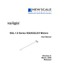
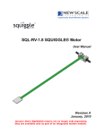
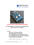
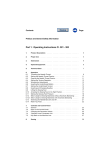
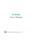
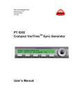
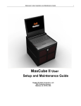
MC-3300-RV Motor Controller
for SQL-RV-1.8 Series
Reduced Voltage SQUIGGLE® Motors
User Manual
Revision A
January, 2010
January 2014 - Discontinued Product
New Scale Technologies, Inc
121 Victor Heights Parkway
Victor NY, 14564
Phone: (585)-924-4450
Fax: (585)-924-4468
Sales: [email protected]
Service: [email protected]
Web: www.newscaletech.com
© 2009 New Scale Technologies, Inc. All rights reserved. No part of this publication may be
reproduced, stored in a retrieval system or transmitted, in any form or by any means, electronic
or mechanical, including photocopying, recording, or otherwise, without the prior written
permission of New Scale Technologies, Inc
SQUIGGLE is a registered trademark of New Scale Technologies, Inc.
Windows, Vista and ActiveX are registered trademarks of Microsoft Corporation.
02558-6-0000, MC-3300-RV Controller User Manual
Rev A
Table of Contents
Table of Contents................................................................................................................. i
Introduction......................................................................................................................... 1
New Scale Pathway Software ......................................................................................... 1
Open-Loop or Closed-Loop Operation........................................................................... 2
Mother Board/Daughter Board Configuration................................................................ 2
Difference between MC-3300 and MC-3300-RV .......................................................... 2
System requirements....................................................................................................... 2
Safety .................................................................................................................................. 3
General Safety Summary ................................................................................................ 3
Safety Terms and Symbols ............................................................................................. 4
Warnings and Cautions ............................................................................................... 4
Set up the SQUIGGLE® Motor ......................................................................................... 5
The MC-3300-RV Controller Pin Connections ................................................................ 13
Power Connector (J1) ................................................................................................... 13
Analog and Limit Flag Input Connector (J2)................................................................ 14
USB Connector (J3)...................................................................................................... 14
Program Connector (J4)................................................................................................ 15
SQ-2301/SQ-2301M Multi-Axis (Motor) Handset Connector (J5) ............................. 15
Mother/Daughter Board Connector (J6) ....................................................................... 16
Daughter Board Motor Connectors (J3, J4).................................................................. 16
Daughter Board Motor Flex Circuit FPC Connectors (J6, J5)...................................... 16
Specifications.................................................................................................................... 17
MC-3300-RV Controller............................................................................................... 17
New Scale Pathway Software ....................................................................................... 17
SQL-RV-1.8 Motor....................................................................................................... 18
Troubleshooting ................................................................................................................ 19
Troubleshooting chart ................................................................................................... 19
Maintenance...................................................................................................................... 21
Re-threading the Screw................................................................................................. 21
Cleaning the Screw ....................................................................................................... 21
To Clean the Screw:.................................................................................................. 21
Schematics ........................................................................................................................ 22
Register Map................................................................................................................. 27
Control Register ............................................................................................................ 27
Period Counter .............................................................................................................. 27
Pulse Counter ................................................................................................................ 28
Pulse Width Control...................................................................................................... 28
Phase Shift .................................................................................................................... 29
Period Offset ................................................................................................................. 29
Hybrid Speed Register .................................................................................................. 30
Index ................................................................................................................................. 31
02558-6-0000, MC-3300-RV Controller User Manual
Rev A
Page: i
Introduction
The MC-3300-RV (Reduced Voltage) Motor Controller generates ultrasonic signals to drive two
SQL-RV-1.8 Series SQUIGGLE Motors in open-loop or closed-loop operation.
Figure 1. MC-3300-RV Motor Controller for SQL-1.8 RV Series SQUIGGLE® Motors
The controller sends drive signals to one or two SQUIGGLE motors based on the input from a computer
or a manual handset.
•
•
Computer Control – Connect the MC-3300-RV to a PC USB port: The control software
enables simple point-and-click operation of the motor. You can also build and run scripts
using the intuitive scripting environment, or write routines using your own software and
the included ActiveX function library.
Manual Control – Use the optional handset to control the motor (See page Error!
Bookmark not defined.).
New Scale Pathway Software
The control software provided with the MC-3300-RV
Motor Controller enables point-and-click control via a PC
USB port. It also includes a scripting interface and an
ActiveX command library.
Each MC-3300-RV Motor Controller can operate one or
two SQUIGGLE motors, and you can manage multiple
motor controllers simultaneously from a single control
software window.
The control software and scripting interface allow you to
easily evaluate open-loop and closed-loop performance of
SQL Series SQUIGGLE motors.
02558-6-0000, MC-3300-RV Controller User Manual
Rev A
Page: 1
Open-Loop or Closed-Loop Operation
We recommend closed-loop operation when repeatable step size, absolute position or precise velocity
control is needed. The MC-3300-RV accepts input from remote position sensors or switches for
closed-loop motion control.
With a digital (incremental) encoder as a position sensor, the resolution of the encoder determines
closed-loop position resolution. With an analog position sensor, closed-loop position resolution is
determined by the A/D converter, the resolution of the position sensor, and the resolution of the motor.
For more information see the New Scale Application Note: Creating Closed-Loop Positioning Systems
Using SQUIGGLE Motors.
In open-loop mode, you can calibrate a motor’s average step size in response to a number of drive pulses.
Open-loop resolution is listed on the motor data sheets.
Mother Board/Daughter Board Configuration
The MC-3300-RV Motor Controller is a mother board/daughter board configuration. The mother board
includes the processor, position sensor input with 12-bit A/D converter, limit switch input and PC/handset
interface. The daughter board contains the motor driver ASIC, related boost circuit, and two motor
connectors.
Both the daughter board (MC-33DB-RV) and ASICs (two NSD-2101) are also available separately for
integration into OEM systems. See the separate data sheets for more information. We work closely with
OEM customers to develop integrated SQUIGGLE motor systems including position sensors, housings,
and controllers designed for your unique needs.
Difference between MC-3300 and MC-3300-RV
The MC-3300 Motor Controller uses the MC-33DB daughter board which incorporates a single NSD1202 dual motor driver ASIC. This ASIC uses an external inductor, diode and capacitor to boost the
supply voltage (2.3V to 5.5V) to up to 40V to drive the SQL motor. One ASIC drives up to two motors.
The MC-3300-RV Motor Controller uses the MC-33DB-RV daughter board which incorporates two
NSD-2101 driver ASICs. Each ASIC can drive a single SQL-RV-1.8 motor at the supply voltage (2.3V
to 5.5V, there’s no voltage boost). The NSD-2101 ASIC, in the WLCSP package is much smaller than
the NSD-1202 QFN (1.8x1.8mm vs. 4x4mm) and it requires only two external capacitors (0.47 uF and 10
uF respectively).
The SQL-RV-1.8 motors, although the same size as the SQL-1.8 motors use multi-layer piezo plates
rather than the single layer piezos used by the SQL-1.8 motors. These extra layers boost the motor
capacitance and reduce the required voltage needed to achieve equivalent motor performance.
System requirements
•
Computer with a CD drive; Windows 2000, XP Pro or Vista.
02558-6-0000, MC-3300-RV Controller User Manual
Rev A
Page: 2
Safety
Review the following safety precautions to prevent injury and avoid damage to this product. Use this
product only as specified. Service procedures should only be performed by qualified personnel.
Follow these guidelines to insure safe and reliable operation of this product:
•
•
•
•
•
•
•
Use Proper Power Cord. Use only the power cord specified for this product and certified
for the country of use.
Connect and Disconnect Properly. Do not connect or disconnect components while
power is on. Unplug the power connection from the back of the unit before connecting or
disconnecting any cables.
Avoid Physical Shocks to the Motor. The motor contains a piezoelectric actuator
susceptible to excessive shock
Do Not Apply Side Loads the Motor Shaft. Excessive side loads may damage the motor.
Always apply loads axially to the motor shaft.
Do Not Retract Beyond Limit. Do not allow the motor to overrun its travel limits when
moving backwards. The threaded shaft may disengage from the internal threads. If this
happens gently re-insert the screw until the threads are re-engaged and turning smoothly.
Avoid Contact with Internal Electronic Circuitry. High voltage is present inside the
controller and motor when activated. Do not touch connections and components when
power is on.
Call Us If You Have a Problem or Question. If your system is not operating within
specifications or you have questions please contact us. Our service and support team is
eager to help.
General Safety Summary
•
•
•
•
Do Not Operate in Wet/Damp Conditions.
Do Not Operate in an Explosive Atmosphere.
Do not Operating in the corona vacuum pressure range from 100 Torr to 10-3 Torr.
Keep Product Surfaces Clean and Dry.
02558-6-0000, MC-3300-RV Controller User Manual
Rev A
Page: 3
Safety Terms and Symbols
This symbol indicates potentially dangerous voltages may be present when
the motor is operating.
Only use an approved DC power supply or as provided by New Scale
Technologies, Inc.
Certain components are susceptible to damage from electrostatic discharge.
Observe all ESD procedures to avoid component damage
Warnings and Cautions
These terms may appear in this manual:
WARNING identifies conditions or practices that could result in damage, injury or loss of life.
CAUTION identifies conditions or practices that could result in damage to this product or other
property.
DANGER indicates an injury hazard immediately accessible as you read the marking.
02558-6-0000, MC-3300-RV Controller User Manual
Rev A
Page: 4
Set up the SQUIGGLE® Motor
Use the following instructions to set up and begin using your SQUIGGLE® motor and MC-3300-RV
controller. If you have purchased a Developer’s Kit, connections will already have been made. Proceed
to Section 2 below.
1. Connect the motor(s) to the controller.
You can connect the motor directly to the controller, or use the extension cable (provided) if
you need more length between the motor and controller. The MC-3300-RV controller is
capable of driving to one or two motors.
a. Direct Connection
Flex circuit
Flip up the brown tab on the controller
daughter board at J6 (and J5, if you
have two motors).
With the copper connection side down,
gently slide the motor flex circuit into
place. Close the tab.
Caution: Allow some bend in the flex
circuit to avoid damaging solder
connections.
Flip brown tab to open
Controller
Pre-mounted
motor
J6 (motor 1)
J5 (motor 2)
02558-6-0000, MC-3300-RV Controller User Manual
Rev A
Page: 5
2. Connect the controller to your PC or handset
Connect the Mini USB connector to the controller at J3
on the mother board. Then connect the USB cable to your
computer.
Mini USB connector
J3
3. Connect the power
If you have purchased a Developer’s Kit, batteries are
provided, so there is no need to connect an input cable
and external power supply. Press the On/Off switch on
the Developer Kit to the “On” position and proceed to
Section 4.
J1 is a keyed
connector observe
polarity. Do
not force.
Power
input
cable
Connect the power input cable to the controller at J1 on
the mother board.
Caution: The power input cable has a keyed connector
that fits only one way. It should never be forced. The red
wire should connect to pin 1.
J1
Plug the power input cable into the power supply.
Be sure to connect the power input cable to the controller
before you apply power.
Power supply
Plug the power supply to a power source. An LED on the
controller lights when power is applied.
Power input cable
Install the New Scale Software
Next, install the New Scale software to control the motor from your PC.
(You may skip this step if you will be using ONLY the optional manual handset.)
02558-6-0000, MC-3300-RV Controller User Manual
Rev A
Page: 6
a. Locate the software
installation disk.
b. Place the disk in the
computer drive.
The NST installer window will
appear automatically.
Do not connect the MC-3300RV controller yet!
c. Identify the motor/encoder
controller provided with
your order.
d. Select the controller from
the list in the “Choose Your
Controller” menu.
e. If an encoder is included
in the order, check the
“Include Support for
Tracker Sensor” check box.
f. Click “Install” to install the
software.
If a Microsoft warning appears,
click OK to continue.
02558-6-0000, MC-3300-RV Controller User Manual
Rev A
Page: 7
You may also view the New Scale
manuals or save them to disk at this
time.
When the installation is complete,
remove the disk.
g. Connect the USB cable
from the computer to the
controller as shown.
The first time the USB
connection is made, the system
will install a USB driver and
motor driver on the local hard
drive
Instruct the system to find the
drivers locally.
02558-6-0000, MC-3300-RV Controller User Manual
Rev A
Page: 8
Do the following to run the Pathway
demo software and select the
communication port.
h. Double Click on the New
Scale Pathways icon on
desktop to start
application.
i. Click on “Setup Connection”
to open connection dialog.
j. Select the desired USB port
(that you wish to connect
the controller to).
Highlight the desired USB
port and click “Select” to
select the port.
k. Click the “Test Selected
USB/COM Ports…” button
to test the selected port.
Click “Close” when the
connection is complete.
02558-6-0000, MC-3300-RV Controller User Manual
Rev A
Page: 9
4. Begin Using the Motor
•
Click the Connect button in
the main menu to connect to
the controller.
•
Two motors are always listed
in the motor control window.
Highlight the desired motor.
•
Click the Fwd and Rev Run
Control and Jog Control
buttons to move the motor as
you observe motor operation.
Encoder equipper systems
will display position.
See the New Scale Pathways
Software manual for more
detailed operating
instructions.
02558-6-0000, MC-3300-RV Controller User Manual
To change the motor speed: change the
Motor Step Control values or use the
%Max Speed slide bar. Note that the motor
step values are only used with the Rev &
Fwd buttons contained within the same group
box.
Rev A
Page: 10
IMPORTANT NOTE:
When you wish to shut down the
controller click the Disconnect
button before you remove the USB
cable.
•
Test encoder (Tracker)
operation.
Select the Tracker tab to
display the Tracker data
screen, which shows
available axes plus detailed
information for encoder
program development.
See the New Scale Pathways
Software manual for full
programming details.
02558-6-0000, MC-3300-RV Controller User Manual
Rev A
Page: 11
5. What’s Next?
Consult the SQL-RV-1.8 Series SQUIGGLE® Motors Use Manual or New Scale
Pathway Software Manual on the enclosed CD for more details on how to use the
controller to drive the SQUIGGLE motor.
Your SQL-RV-1.8 SQUIGGLE motor is mounted in a sheet metal frame. Refer to the
Mechanical Integration section of the SQL-RV-1.8 Series SQUIGGLE® Motors Use
Manual for details on how to mount and integrate the SQL-RV-1.8 motor into your
product.
Contact New Scale if you need assistance with your evaluation unit, or to discuss custom
motors and motion control modules.
02558-6-0000, MC-3300-RV Controller User Manual
Rev A
Page: 12
The MC-3300-RV Controller Pin Connections
The MC-3300-RV consists of two printed circuit boards: A mother board, which contains the power,
PC/Handset, position sensor and travel limit interfaces, and a daughter board which contains the motor
driver ASIC (NSD-2101) and motor connector interface. The daughter board may be removed and
interfaced to 3rd party hardware as it supports an I2C command interface.
Figure 2. MC-3300-RV Controller Pin Connections
Power Connector (J1)
Pin
Pin Name
Description
1
Vin
Main supply input (2.3 to 5.5 volts).
2
GND
Ground reference
02558-6-0000, MC-3300-RV Controller User Manual
Rev A
Page: 13
Analog and Limit Flag Input Connector (J2)
Pin
Pin Name
Description
1
AN5
Axis (Motor) 1 Quadrature Input B
2
INT1
Axis 1 (Motor) AF Reverse Limit. Active Low
3
AN4
Axis 1 (Motor) Quadrature Input A
4
INT0
Axis 1 (Motor) AF Forward Limit. Active Low
5
AN3
Axis 2 (Motor) Quadrature Input B (or Axis 2 Analog
Sensor Input)
6
RD3
Axis 2 (Motor) Zoom Reverse Limit. Active Low
7
AN2
Axis 2 (Motor) Quadrature Input A (or Axis 1 Analog
Sensor Input)
8
RD2
Axis 2 (Motor) Zoom Forward Limit. Active Low
9
Vcc
3.3 Volts
10
GND
Ground Connection
Note: AN5 and AN4 are connected to the processor’s internal quadrature counter. AN3 and AN2 are
polled in firmware. This limits either the resolution of the incremental encoder for Axis (Motor) 2 or the
maximum speed of Axis 2 so that encoder edges are not missed.
USB Connector (J3)
This is a standard USB connector jack. The pins beneath the jack are defined as follows.
Pin
Pin Name
Description
1
Vbus
USB Voltage
2
D+
Data
3
D-
Data
4
GND
Ground
5
Shell
Shell Connection to Ground
6
Shell
Shell Connection to Ground
02558-6-0000, MC-3300-RV Controller User Manual
Rev A
Page: 14
Program Connector (J4)
Pin
Pin Name
Description
1
PDC
dsPIC data clock
2
Vcc
3.3 Volts
3
PGD
dsPIC data
4
VIN
Power from J1 pin 1
5
/MCLR
Processor reset and Vpp program voltage connect
6
GND
Ground connection
7
SDA
I2C Data Line
8
ACM
Analog Drive Current Monitor
9
SCL
I2C Clock Line
10
NC
Not Connected
SQ-2301/SQ-2301M Multi-Axis (Motor) Handset Connector (J5)
The SQ-2301M may be used to control motor 1 or 2.
Pin
Pin Name
Description
1
Vcc
3.3 Volts
2
GND
Ground connection
3
B
RS485 connection B
4
A
RS485 connection A
02558-6-0000, MC-3300-RV Controller User Manual
Rev A
Page: 15
Mother/Daughter Board Connector (J6)
Pin
Pin Name
Description
1
VIN
Power from J1 pin 1 (2.3V to 5.5V)
2
GND
Ground connection
3
NC
Not used by MC-33DB-RV
4
SDA
I2C Data Line
5
SCL
I2C Clock Line
6
XPD
NSD-2101 Enable Line
Daughter Board Motor Connectors (J3, J4)
Use these connectors if you use the motor extension cable.
If the forward direction of motion is the opposite of what you would like, reverse the FOUT1/ZOUT1 and
FOUT2/ZOUT2 connections.
Pin
Pin Name
Description
1
FOUT1/ZOUT1
Motor Focus (J2) or Zoom (J6) Phase 1
2
GND
Motor return connect
3
FOUT2/ZOUT2
Motor Focus (J2) or Zoom (J6) Phase 2
Daughter Board Motor Flex Circuit FPC Connectors (J6, J5)
Use these connectors if you are connecting the motor flex circuit directly to the MC-3300-RV Controller without using
the extension cable.
Pin
Pin Name
Description
1
GND
Motor return connect
2
GND
Motor return connect
3
FOUT1/ZOUT1
Motor Focus (J6) or Zoom (J5) Phase 1
4
FOUT2/ZOUT2
Motor Focus (J6) or Zoom (J5) Phase 2
5
FOUT1/ZOUT1
Motor Focus (J6) or Zoom (J5) Phase 1
6
FOUT2/ZOUT2
Motor Focus (J6) or Zoom (J5) Phase 2
02558-6-0000, MC-3300-RV Controller User Manual
Rev A
Page: 16
Specifications
MC-3300-RV Controller
Item
Specification
Input power
2.3 to 5.5 V DC
Output signals
Motor 1 – Phase 1, Phase 2, Ground
Motor 2 – Phase 1, Phase 2, Ground
Computer control
Via USB port
Demo software and ActiveX command library
included
Position sensor input
Digital or analog
A / D converter resolution
12 bits
Manual commands
See Appendix C
Dimensions (L x W x H)
1.150 x 2.275 x 0.875 inches
(29.21 x 57.785 x 22.225 mm)
New Scale Pathway Software
System Requirements
PC running Windows XP or Vista
20 MB storage (minimal)
02558-6-0000, MC-3300-RV Controller User Manual
Rev A
Page: 17
SQL-RV-1.8 Motor
Electrical specifications below assume that the motor is driven by an MC-3300-RV controller.
Item
SQL-RV-1.8
Travel range
6 mm
SQL-RV-1.8-6-12: 12
mm screw length
Stator dimensions
1.82 x 1.82 x 6 mm
Housing dimensions
2.8 x 2.8 x 6 mm
Stall force
30 gram force (0.3 N)
Speed at ½ stall force
>7 mm/s
Resolution
0.5 µm
Input power to MC-3300RV (moving)
1.45 W
Input power to motor
(moving)
< 500 mW (direct drive)
Input power (stopped)
0 mW (0 V) to hold
position
Lifetime (load-dependent)
>1,000,000 cycles
Operating temperature
-30 to +80 degrees C
Storage temperature
-40 to +85 degrees C
Shock resistance
2500 Gs
Operating frequency
~ 171 KHz
Capacitance per phase
~ 42 nF
Mounting
Potting or flange; see
the Mounting section of
the SQL-RV-1.8 Series
SQUIGGLE® Motors
User Manual.
Weight
0.16 grams
02558-6-0000, MC-3300-RV Controller User Manual
Rev A
Page: 18
Troubleshooting
Troubleshooting chart
If the following remedies do not work, call New Scale Technologies for service.
Symptom
Causes
Remedies
Controller LED does
not light.
Power supply not connected
or improperly connected.
Connect the power input cable to the
controller at J1 on the mother board.
Caution: The power input cable has a
keyed connector that fits only one way.
It should never be forced. The red
wire should connect to pin 1.
Controller set on metallic
surface.
Properly insulate the bottom of the
controller.
Motor incorrectly installed.
Lift tab on FPC connector and fully
insert motor connector.
Wrong axis (motor) selected
in New Scale Pathways
software.
Select the correct axis (motor) on the
Motor Control tab of the New Scale
Pathways software..
Too much load on motor.
Check the Test Data sheet shipped
with the motor and motor specifications
for maximum motor load.
Motor shorted.
Move metallic surfaces away from the
motor.
Crimped or broken flex
circuit.
Check for damage to the flex circuit.
Too much progressive load
on motor.
Reduce progressive load.
Dirty screw.
Clean screw. See “Cleaning the
Screw” on page 21.
Controller timeout error.
Recycle power and restart Demo
software.
Motor mount not securely
fastened.
Verify that motor mount is securely
fastened to your test bench or fixture.
Too much load on motor.
Reduce motor load.
Low speed setting in Demo
software.
Raise the speed setting in the Demo
software.
Dirty screw.
Clean screw. See “Cleaning the
Screw” on page 21.
Too much load on motor.
Reduce the motor load.
Check mounting fixture.
Motor does not move.
Motor moved initially
but stopped moving.
Motor does not push
to spec.
Slow motor speed.
02558-6-0000, MC-3300-RV Controller User Manual
Rev A
Page: 19
Symptom
Causes
Remedies
No available USBbased controllers
listed after using
Setup Connection
button.
The USB driver may not be
installed or after the
controller was connected to
the PC and powered,
Windows may have asked to
reinstalled the driver and this
request was ignored by the
operator
Reinsert the NST demo software CD
and select the MC-3300-RV controller
to see if the USB driver must be
installed. If it is shown, click Install to
force an installation.
If it’s not shown in the list box below, it
is already on the system.
If already installed, disconnect and
reconnect the USB cable and see if
Windows prompts to reinstall the
driver, if so, let it find the driver locally.
Screw runs completely
out of motor shaft.
Motor run for too long in one
direction.
Re-thread the screw. See
“Re-threading the Screw“ on page 21.
02558-6-0000, MC-3300-RV Controller User Manual
Rev A
Page: 20
Maintenance
Re-threading the Screw
If you run the motor for too long in one direction, it can run completely out of the motor shaft.
If this occurs, carefully re-thread the screw clockwise, with either end facing into the motor shaft.
Cleaning the Screw
The SQUIGGLE motor normally performs well in an open setting without any contamination. This is true
whether or not the motor is integrated in a module or housing.
Occasionally, dirt particles may accumulate on the screw, which can reduce motor performance. If this
happens, clean the screw.
To Clean the Screw:
1. Clean the screw using acetone in an ultrasonic cleaner. If an ultrasonic cleaner is not
available, simply rinse the screw with acetone.
2. Allow the screw to air dry or dry it using clean compressed air, such as an air can duster.
02558-6-0000, MC-3300-RV Controller User Manual
Rev A
Page: 21
Schematics
This section includes top layout view of each board followed by the schematics.
Figure 3. Mother Board Layout.
Figure 4. Daughter Board Layout.
02558-6-0000, MC-3300-RV Controller User Manual
Rev A
Page: 22
Figure 5. Mother Board Schematic (1 of 2).
02558-6-0000, MC-3300-RV Controller User Manual
Rev A
Page: 23
Figure 6. Mother Board Schematic (2 of 2).
02558-6-0000, MC-3300-RV Controller User Manual
Rev A
Page: 24
Figure 7. Daughter Board Schematic (1 of 1).
02558-6-0000, MC-3300-RV Controller User Manual
Rev A
Page: 25
NSD-2101 I2C Control
This section is intended for use by individuals who will be interfacing directly to the MC-33DB-RV
daughter board (rather than via the MC-33MB Mother Board).
The connector pins of the MC-33DB-RV Board
which contains the
NSD-2101 Motor Driver
The I2C interface is used to control the NSD-2102 SQL Motor Driver chip
(via the MC-33DB-RV Daughter board) and to set the value of several
registers. These registers will define the output voltage (by changing the
resistive feedback divider) as well as the direction and duration of the output
driver signals. Period count and pulse count registers can be set separately
for both motors.
A HIGH to LOW transition on the SDA line while SCL is HIGH is the start
condition for the bus. A LOW to HIGH transition on the SDA line while
SCL is HIGH is the stop condition.
Every byte put on the SDA line must be 8-bits long. Each byte has to be
followed by an acknowledge bit. Data is transferred with the most significant
bit (MSB) first.
Data transfer with acknowledge is obligatory. The acknowledge-related clock
pulse is generated by the master. The receiver must pull down the SDA line
during the acknowledge clock pulse.
The NSD-2101 is a slave device on the bus. The device can be addressed
using 7-bits addressing.
There are two different access modes to the slave possible. These are:
Note: The XPD input
(above) must be
HIGH in order to
communicate with
the NSD-2101
•
•
byte write
page write
Provision will be made for data collision due to non-synchronization
between the external clock and the internally generated clock.
7-Bit Addressing: the first 6 bits are fixed (could be modified by metal mask change) and the last bit can
be set via package pin.
Motor 1
Address: 54
Byte Write
7 bit device
address
Page Write
7 bit device
address
Typ identifier
7 bit addressing
Pin selectable
Address
1 0 1 0 1 0 X
X X X X X X X X
Slave Address
Register Address
Typ identifier
7 bit addressing
X X X X X X X X
Data Byte (n)
Motor 2
Address: 55
Pin selectable
Address
1 0 1 0 1 0 X
X X X X X X X X
Slave Address
Register Address
X X X X X X X X
X X X X X X X X
X X X X X X X X
Data Byte (n+1)
Data Byte (n)
Data Byte (n+2)
Figure 8. 7-Bit Addressing (54 and 55 Hexadecimal Respectively)
02558-6-0000, MC-3300-RV Controller User Manual
Rev A
Page: 26
Register Map
The table below shows the registers which can be addressed over the I²C interface.
Description
Address
Data Byte
Note
MSB
Control Register
Period count
Pulse count (high byte)
Pulse count (low byte)
Pulse width
Phase shift
Period offset
Hybrid speed
Reserved register
00h
01h
02h
03h
04h
05h
06h
07h
10h
X
P
X
X
X
IDL
X
X
LSB
PS[1]
X
D
X
X
X
HB
X
X
PS[0]
X
DS[1]
X
X
X
HYB
X
X
X
DS[0]
X
X
X
DT
X
X
CN[1]
X
X
X
X
X
X
CN[0]
X
X
X
X
X
X
X
X
P1
X
X
X
X
X
X
X
X
P2
X
X
X
X
X
X
X
X
(1)
(2)
(4)
(3)
Notes:
(1)
P: period count MSB; D: direction bit; DS: dead time selection bits: ‘00’=2, ‘01’=4, ‘10’=6 and ‘11’=8 VCO clocks;
(2)
CN needs to be 00 to enable Period offset, Period offset is not used when either Incremental or Sweep Frequency Tracking is
active. IDL: sets idle mode; HB: enable half bridge operation if VDD > HBth; HYB: enable hybrid speed control; DT: enable
signal for increased dead time; Selection bits(DS[1:0]) are only valid when DT=1; Selection bits should not be changed when
the output driver is active.
(3)
Reserved register used for device test only, not accessible during normal operation.
(4)
Hybrid Speed register: 0 .. half bridge; 128 .. full bridge operation; linear transition for values in between; Default: 128. Values
from 1 to 127 are used for linear speed control.
Control Register
The control register is used to trigger frequency calibration as well as to select and enable the drive phases.
Control flag mask
Abbr
1000 0000
Default
Description
0
Reserved (leave 0)
0100 0000
PS[1]
1
Phase Select for sensing: PS[1] PS[0]:
0010 0000
PS[0]
1
00=None; 01=Phase1; 10=Phase2; 11= Both Phases;
0
Reserved (leave 0)
0001 0000
0000 1000
CN[1]
0
Calibrate Now: CN[1] CN[0]:
0000 0100
CN[0]
0
00=None; 01=Incremental; 10=Sweep; 11=reserved;
0000 0010
P1
1
Enable Phase1
0000 0001
P2
1
Enable Phase2
Period Counter
The period counter is used to define the switching frequency of the motor. The pulse period is generated by dividing the
internal VCO clock frequency by the given period counter value. The MSB of high byte of the pulse counter (p) is used as
MSB of the period counter.
At 25MHz clock a decimal period counter value of 125 gives an output frequency of 200 kHz. A period counter value of
126 results in a switching frequency of 198.41 kHz. This is equal to a maximum frequency step of 1.59 kHz. The
frequency resolution gets better for lower switching frequencies assuming a fixed VCO clock frequency.
02558-6-0000, MC-3300-RV Controller User Manual
Rev A
Page: 27
In the following table a few examples are given to define period counter and output switching frequency relation ship. The
values are given for 25MHz typical VCO clock frequency.
The switch frequency is given as: fD = 25MHz / period counter value;
Period counter value
Typ
0 0111 1101
200.00
Unit
kHz
0 0111 1110
198.41
kHz
0 1000 1010
181.16
kHz
0 1010 0110
150.60
kHz
0 1010 0111
149.70
kHz
1 1111 0011
50.10
kHz
1 1111 0100
50.00
kHz
Pulse Counter
The pulse counter sets the number of pulses the motor should be active. When a new value is written to the pulse count
register an internal counter is started to count generated output pulses. Writing all zeros to the pulse counter stops the
motor even if the previous set counter value is not completed, all outputs pulled to ground. The same is valid for power
down mode. Bit 6 in the pulse counter (d) is used to set the direction of motor motion.
Pulse counter value
XXXX X000 0000 0000
XXXX X100 0000 0000
XXXX X111 1111 1111
Typ
0
1024
2047
Unit
pulses
pulses
pulses
Conditions
Motor is off, driver outputs are low
Maximum possible number of pulses
Pulse Width Control
A register is used to define the duty cycle of the driver output signal. The default value for this register set during power
up or power down (XPD = LOW) is equal to 00h. In this case the default duty cycle of 50% is generated. The resulting
duty cycle and resolution of single steps is depending on the master clock frequency and the switching frequency of the
driver output. In the following table an example for 25MHz master clock and 200kHz driver frequency is given. The value
of the duty cycle register should not exceed 50.4% of the period counter value. Pulse Width Modulation is used for speed
control when motor is operating in half bridge mode.
Pulse width register
Typ
Unit
0000 0000
49.6/50.4
%
0000 0001
0.8
%
0000 1101
10.4
%
0001 1011
21.6
%
0011 0101
42.4
%
0011 1110
49.6
%
0011 1111
50.4
%
Conditions
default
02558-6-0000, MC-3300-RV Controller User Manual
Rev A
Page: 28
If operating in half bridge mode, the pulse width can be used to adjust speed. At 50% the motor will operate
at its maximum speed. To reduce the speed, the pulse width may be reduced. However, below ~15%, there
may not be enough energy in the signal to move the motor.
Phase Shift
A register is used to define the phase shift between the two phases of the driver output signal. The default value for this
register set during power up or power down (XPD = LOW) is equal to 00h. In this case the default phase shift of 90° is
generated. The resulting phase shift and resolution of single steps is depending on the master clock frequency and the
switching frequency of the driver output. In the following table an example for 25MHz master clock and 200kHz driver
frequency is given. The value of the phase shift register should not exceed 50.4% of the period counter value.
Negative phase shift values are achieved by changing the direction bit: -160deg = 20deg and inverted direction bit.
Phase shift register
Typ
Unit
0000 0000
90.5
deg
0000 0001
2.88
deg
0000 1101
37.44
deg
0000 1110
40.32
deg
0001 1111
89.28
deg
0010 0000
92.16
deg
Conditions
Default (Normal for both SQL and UTAF)
Period Offset
Period Offset register defines the offset which is added to the period counter to shift the switching frequency. It also
provides some additional control bits.
This offset is only activated when frequency tracking is stopped. An offset has been provided as some types of motors
operate better at slightly below mechanical resonance. The table below gives an example for 25MHz master clock and
200kHz nominal driver frequency. Period offset is only supposed to lower drive frequency.
Period offset register
Typ
Unit
Conditions
0000 0000
0
%
0000 0001
-0.8
%
0000 0010
-1.6
%
0000 0111
-5.6
%
Maximum period offset
1000 0000
0
%
Idle mode enabled
0100 0000
0
%
Half bridge mode enabled
0010 0000
0
%
Hybrid speed control enabled
0001 0000
0
%
Increased dead time enabled
default, no change of drive frequency
02558-6-0000, MC-3300-RV Controller User Manual
Rev A
Page: 29
Idle mode reduces power consumption while preserving the most recent frequency calibration. To further reduce power,
the XPD pin must be pulled to ground.
Hybrid Speed Register
The hybrid speed register allows the average voltage as seen by the motor to be set from VDD to 2 x VDD. This provides
a power efficient method of reducing the speed of the motor. The value of the register can vary from 0 (half bridge) to
128 (full bridge). The average voltage can be calculated in the following manner.
VAVG = VDD + (RegisterValue * VDD/128);
Hybrid speed register
Where VDD is the supply voltage.
Typ
Unit
Average Voltage
0000 0000
0
%
VDD (half bridge)
0010 0000
25
%
VDD + 0.25 * VDD
0110 0000
75
%
VDD + 0.75 * VDD
1000 0000
100
%
VDD + VDD (full bridge)
02558-6-0000, MC-3300-RV Controller User Manual
Rev A
Page: 30
Index
7-Bit Addressing, 27
Analog and Limit Flag Input Connector (J2),
14
Begin Using the Motor, 10
Cleaning the Screw, 22
Closed-Loop Operation, 2
Connect the controller to your PC or handset,
6
Connect the motor(s) to the controller, 5
Connect the power, 6
Connector (J1)
Mother Board, 13
Connector (J2)
Mother Board, 14
Connector (J3)
Daughter Board, 16
Mother Board, 14
Connector (J4)
Daughter Board, 16
Mother Board, 15
Connector (J5)
Daughter Board, 16
Mother Board, 15
Connector (J6)
Daughter Board, 16
Mother/Daughter Board, 16
Daughter Board, 2
Daughter Board
Connectors (J3, J4), 16
Daughter Board
Connectors (J6, J5), 16
Daughter Board Layout, 23
Daughter Board Motor Connectors (J3, J4), 16
Daughter Board Motor Flex Circuit FPC
Connectors (J6, J5), 16
Daughter Board Schematic, 26
Electrostatic discharge, 4
ESD, 4
Flex Circuit FPC Connectors (J6, J5), 16
General Safety Summary, 3
Install the New Scale Software, 7
Introduction, 1
02558-6-0000, MC-3300-RV Controller User Manual
Maintenance, 22
MC-3300 Controller Pin Connections, 13
Mother Board, 2
Connector (J1), 13
Connector (J2), 14
Connector (J3), 14
Connector (J4), 15
Connector (J5), 15
Mother Board Layout, 23
Mother Board Schematic, 24
Mother Board/Daughter Board Configuration,
2
Mother/Daughter Board Connector (J6), 16
New Scale Pathway Software, 1, 17
NSD-1102 I2C Control, 27
Open-Loop Operation, 2
Pathway Software, 1, 17
Pin Connections, 13
Power Connector (J1), 13
Program Connector (J4), 15
Register Map, 28
Re-threading the Screw, 22
Safety, 3
Safety Terms and Symbols, 4
Schematic
Daughter Board, 26
Mother Board, 24
Schematics, 23
Screw
Cleaning, 22
Re-threading, 22
Set up the SQUIGGLE® Motor, 5
Software, 1, 17
SQ-2301/SQ-2301M Multi-Axis (Motor)
Handset Connector (J5), 15
SQL-1.5 and SQL-1.8 Motors, 18
System requirements, 2
Troubleshooting, 20
Troubleshooting chart, 20
USB Connector (J3), 14
Warnings and Cautions, 4
What’s Next?, 12
Rev A
Page: 31
Notes:
New Scale Technologies, Inc.
121 Victor Heights Parkway
Victor NY, 14564
Phone: (585) 924-4450
Fax: (585) 924-4468
Sales: [email protected]
Service: [email protected]
Web: www.newscaletech.com