1
Home
Contents
Page:
Preface and General Safety Information
Part 1: Operating Instructions Cl. 381 - 382
1.
Product Description
. . . . . . . . . . . . . . . . . . . . . . . . . . .
5
2.
Proper Use . . . . . . . . . . . . . . . . . . . . . . . . . . . . . . . . .
5
3.
Subclasses . . . . . . . . . . . . . . . . . . . . . . . . . . . . . . . . .
6
4.
Optional Equipment . . . . . . . . . . . . . . . . . . . . . . . . . . . .
6
5.
Technical Data . . . . . . . . . . . . . . . . . . . . . . . . . . . . . . .
7
6.
6.1
6.2
6.3
6.4
6.5
6.6
6.7
6.8
6.9
6.10
6.11
6.12
6.12.1
6.13
6.14
Operation
Threading the Needle Thread . . . . . . . . . . . . . . . . . . . .
Setting the Needle Thread Tension . . . . . . . . . . . . . . . . .
Opening the Needle Thread Tension . . . . . . . . . . . . . . . .
Setting the Tension Regulator . . . . . . . . . . . . . . . . . . . .
Winding the Underthread . . . . . . . . . . . . . . . . . . . . . .
Inserting the Underthread Bobbin . . . . . . . . . . . . . . . . . .
Setting the Underthread Tension . . . . . . . . . . . . . . . . . .
Inserting and Changing Needles . . . . . . . . . . . . . . . . . .
Lifting the Sewing Feet . . . . . . . . . . . . . . . . . . . . . . . .
Arresting the Sewing Feet in the High Position . . . . . . . . . . .
Setting the Sewing Foot Pressure . . . . . . . . . . . . . . . . . .
Stitch Length on Sewing Machines without Automatic Bartacking
Stitch Length on Sewing Machines with Automatic Bartacking . .
Switching the Needle Bars On and Off . . . . . . . . . . . . . . .
Roller Top Feed . . . . . . . . . . . . . . . . . . . . . . . . . . . .
.
.
.
.
.
.
.
.
.
.
.
.
.
.
.
.
.
.
.
.
.
.
.
.
.
.
.
.
.
.
.
.
.
.
.
.
.
.
.
.
.
.
.
.
.
9
11
11
12
13
14
15
16
17
17
18
19
20
21
22
7.
7.1
7.2
7.3
7.4
7.5
Controls and Control Panel
General . . . . . . . . . . . . .
Keys on the Control Panel . . .
Changing the Parameter Values
"Operator Level" Parameter List
Key Bank on the Machine Arm .
.
.
.
.
.
.
.
.
.
.
.
.
.
.
.
23
24
25
26
27
8.
Sewing . . . . . . . . . . . . . . . . . . . . . . . . . . . . . . . . . . .
28
.
.
.
.
.
.
.
.
.
.
.
.
.
.
.
.
.
.
.
.
.
.
.
.
.
.
.
.
.
.
.
.
.
.
.
.
.
.
.
.
.
.
.
.
.
.
.
.
.
.
.
.
.
.
.
.
.
.
.
.
.
.
.
.
.
.
.
.
.
.
.
.
.
.
.
.
.
.
.
.
.
.
.
.
.
.
.
.
.
.
.
.
.
.
.
9.
9.1
9.2
Maintenance
Cleaning and Inspection . . . . . . . . . . . . . . . . . . . . . . . . .
Oil Lubrication . . . . . . . . . . . . . . . . . . . . . . . . . . . . . . .
30
33
10.
10.1
Optional Equipment
Thread Wiper . . . . . . . . . . . . . . . . . . . . . . . . . . . . . . .
34
1. Product Description
The DÜRKOPP ADLER 381 - 382 are special sewing machines for first-class
two-needle decorative seams.
•
•
•
•
•
•
•
Two-needle flat bed double-saddle-stitch machine with bottom and needle feed.
The needles can be turned on and off.
Class 382 additionally with roller top feed.
Slit presser bar (international standard), thus allowing normal commercial sewing
devices to be used.
Existing sewing devices of class 380 can be used.
Central oil wick lubrication with visible reserve in the arm.
Manual hook lubrication.
Integrated winder.
Integrated adjustment disk.
2. Proper Use
The 381 - 382 are special sewing machines which can properly be used for sewing light
sewing material. Such material is, as a rule, fabric composed of textile fibers or leather.
These sewing materials are used in the garment and furniture industries.
Furthermore, it may be possible to also execute so-called technical seams with this
special sewing machine. Here, however, the operator (DÜRKOPP ADLER AG would be
pleased to help) must make an evaluation of the possible dangers since such
applications are, on the one hand, relatively rare and, on the other, their variety is
immense. Depending on the results of this evaluation it may be necessary to adopt
appropriate safety measures.
In general, only dry material may be worked with this special machine. The material
may not be thicker than 8 mm when it is pressed together by the lowered sewing feet.
The material may contain no hard objects because otherwise the sewing unit could only
be allowed to be operated with eye protection.
Such eye protection is not available at this time.
The seam is generally made with sewing yarns of textile fibers with dimensions up to
30/2 Nm (synthetic threads) or 30/3 Nm (core spun threads). Those wishing to use
other threads must also first evaluate the dangers arising herefrom and, if necassary,
take safety measures.
This special sewing machine may only be installed and operated in dry and clean areas.
If the sewing unit is employed in other areas, which are not dry and clean, other, to be
agreed upon, measures may become necessary (see EN 60204-3-1: 1990).
We, as a manufacturer of industrial sewing machines, assume that, at a minimum,
semi-skilled operating personel work on our products so that all normal operations and,
where applicable, their dangers can be presumed to be known.
5
3. Subclasses
Cl. 381 - 160161:
Two-needle flat bed double-saddle-stitch machine with switchable
needles, bottom and needle feed, electromagnetic thread trimmer.
Cl. 381 - 160162:
as Cl. 381 - 160161, additionally with electropneumatic automatic
bartacking and electropneumatic sewing foot lift.
Cl. 382 - 160162:
as Cl. 381 - 160162, additionally with roller top feed
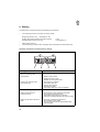
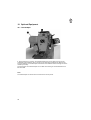
4. Optional Equipment
6
Order no.
Optional Equipment
9822 510001
Sewing light (halogen) WALDMANN,
with 12V/20W lamp, to be attached to the sewing machine head.
OAPP 1241
Sewing light mounting kit, for 9822 510001.
0798 500088
Sewing light transformer
For 230V, with mains cable, without switch,
for sewing lights 9822 510001.
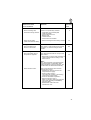
9780 000108
Maintenance unit WE 8
For pneumatic optional equipment.
0797 003031
Pneumatic connection package
For the pneumatic connection of frames with maintenance unit
and pneumatic optional equipment.
Consisting of connection hose (length 5 m, diameter 9 mm),
hose nozzles, hose clamps, coupling socket and coupling
plug.
0381 590014
Electromagnetic thread wiper for Cl. 381
0382 590014
Electromagnetic thread wiper for Cl. 382
N900 001941
Swing rail for apparatus
N900 011038
Edge stop-right, on base plate, fixed
N900 012015
Edge stop-right, on base plate, swing-down
N900 020039
Edge stop-right, on the sewing machine head, swing-up
5. Technical Data
Noise level:
Cl. 381 - 160161
Work station relevant emission value
to DIN 45635-48-A-1-KL2
Lc = __ dB (A)
Stitch length: __ mm
Number of stitches:
3 000 [min-1]
Material: ___________________
Cl. 381 - 160162
Lc = ___ dB (A)
Stitch length: __ mm
Number of stitches:
3 000 [min-1]
Material: ________________
Cl. 382 - 160162
Lc = __ dB (A)
Stitch length: __ mm
Number of stitches:
3 000 [min-1]
Material: ________________
The values were not available at press time !
7
Needle system:
797
Needle thickness (depending on E no.): [Nm]
Seam width / needle clearance:
(depending on E no.)
(70 to 110)
90
[mm]
4.8 11.9 (25.4)
[Nm]
[Nm]
30/2
30/3
[min -1 ]
3 000 *
Max. stitch length:
- Forward:
- Reverse:
[mm]
[mm]
(2 400 stitches/min) 6 *
(2 400 stitches/min) 6 *
Max. sewing foot stroke:
[mm]
10
9
Feed dog stroke:
(above the needle plate)
[mm]
Max. sewing thread thicknesses:
- Synthetic sewing thread
- Core spun thread
Max. number of stitches:
(Cl. 381)
(Cl. 382)
1.1
Max. opening under the sewing feet:
- Sewing
- Raised
[mm]
[mm]
8
10
Operating pressure:
[bar]
6
Air consumption per work cycle: approx. [NL]
0.02
Design voltage:
1 x 230 V, 50 / 60 Hz
Dimensions (H x W x D):
(depending on table top)
[mm]
1750 x 1060 x 500
1750 x 1060 x 600
1750 x 1250 x 900
Work height (ex works):
[mm]
790
approx.[kg]
40
Weight (only machine head):
* At max. stitch length the number of stitches must be reduced to 2 400 stitches/min.
8
6. Operation
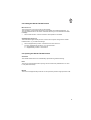
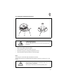
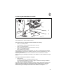
6.1 Threading the Needle Thread
Caution Risk of Injury !
Turn the main switch off !
Thread the needle thread only with the sewing machine
turned off.
–
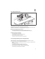
Place the yarn spools on the yarn stand as shown in the illustration and guide the
needle and underthreads through the take-off arms.
The take-off arms 1 and 3 must lie vertically above the yarn spools.
The take-off arms 2 and 4 are to be set as per the drawing.
They prevent the two needle threads from hitting each other.
–
Thread the needle thread as per the drawing on page 10.
3
1
4
2
v a r i o c o n t r o l
7 2 0
P
E
+
6
5
4
1
0
9
8
7
2
3
9
1
A
2
3
10
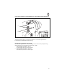
Illus. a:
Correct thread interlacing in the
middle of the material
Illus. b:
Needle thread tension too low
or
Underthread tension too high
Illus. c:
Needle thread tension too high
or
Underthread tension too low
6.2 Setting the Needle Thread Tension
Main tension 3
The main tension 3 is to be set as low as possible.
The interlacing of the threads should lie in the middle of the material (see Illus. a ).
Too high thread tensions can lead to unwanted bunching in thin material and thread
breakage.
–
Set the main tension 3 so that a uniform stitch pattern is achieved.
Supplimentary tension 2
The switchable supplimentary tension 2 serves for the quick change of the needle
thread tension, e.g. at seam thickenings.
–
–
Set the supplimentary tension 2 lower than the main tension 3.
Turn the supplimentary tension 2 on or off with lever 1.
0 = Supplimentary tension 2 is turned off.
1 = Supplimentary tension 2 is turned on.
6.3 Opening the Needle Thread Tension
Automatic
The needle thread tension is automatically opened during thread trimming.
Note
The timing of the thread tension opening can be set with the parameters F-191 and
F-192 (technician level).
Manual
The main and supplimentary tensions can be opened by hand through pressure on A.
11
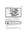
6.4 Setting the Tension Regulator
1
2
3
4
The needle thread quantity required for the hook is adjusted with the tension regulator 2.
The setting is dependent on the following factors:
- Material thickness
- Yarn characteristics
- Stitch length
A prescisely set tension regulator assures an optimal sewing result at the lowest
possible needle thread tension.
With a correct setting, the needle thread loop must glide over the thickest point of the
hook with little tension.
In position " 1 " of the tension regulator the maximum thread quantity is released.
In position " 5 " of the tension regulator the minimum thread quantity is released.
Caution Risk of Injury !
Set tension regular 2 only with the sewing machine turned
off.
–
–
Loosen screws 1 and 3.
–
Tighten screws 1 and 3.
Alter the position of the tension regulator 2.
The scale above the tension regulator serves as a setting aid.
Setting note:
For a correct setting of the tension regulator 2 the following condition must be met:
–
12
When the greatest thread quantity is required, the thread controller spring 4 must
be pulled approx. 0.5 mm up out of its upper end position.
This is the case when the needle thread loop passes the maximum diameter of the
hook.
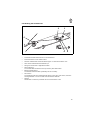
6.5 Winding the Underthread
2
3
5
1
–
–
–
–
–
–
4
6
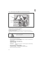
Thread the underthread as shown in the illustrations.
Place the bobbin on the winder shaft 2.
Wind the underthread counterclockwise approx. 5x around the bobbin core.
Tear off the underthread at thread clamp 3.
Swing the winder lever 4 against the bobbin.
Set the tension 1.
The underthread should be wound up uniformly with little tension.
–
Bend the guide plate 5.
The bobbin should be filled cylindrically and not conically.
–
Set screw 6.
The winder should shut off automatically at the correct time, this means, when the
winding diameter is 0.5 mm smaller than the bobbin diameter.
–
Sewing.
Winder lever 4 ends the procedure as soon as the bobbin is full.
13
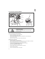
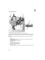
6.6 Inserting the Underthread Bobbin
4
1
2
3
5
6
7
8
Caution Risk of Injury !
Turn the main switch off.
Change the underthread bobbins only with the sewing
machine turned off.
Removing the empty underthread bobbin
–
–
Bring the needle bars into the high position.
–
–
Lift the bobbin case flap.
Open the needle plate slides 1 and 2.
Unlock the right needle plate slide 2 by pressing down on the leaf spring 3.
Remove the bobbin case with empty underthread bobbin.
Threading the underthread
–
Insert a full bobbin 4 into bobbin case 7:
When the thread is being drawn off, the bobbin must turn in the direction of the arrow.
–
–
Pull the underthread through slit 5 under tension spring 6.
–
–
–
–
Cut off the underthread up to approx. 3 cm.
14
Thread the underthread through hole 8 in the bobbin case top.
This assures the thread trimming function.
Insert the bobbin case top with full bobbin into the hook.
Close the bobbin case flap.
Close the needle plate slides 1 and 2 again.
6.7 Setting the Underthread Tension
1
2
3
4
Caution Risk of Injury !
Turn the main switch off.
Set the underthread tension only with the sewing machine
turned off.
–
–
–
–
Take out the bobbin case with bobbin.
To lift the bobbin case reach under the nose 3.
Set tension spring 2 by turning the adjustment screw 1.
Insert the bobbin case with bobbin into the hook again.
Note:
The spring 4 is to be found under the bobbin in the hook.
When thread trimming the underthread automatically it prevents a "running-on" of the
bobbin.
ATTENTION !
The spring 4 must always be in the bobbin case in the
position shown in the sketch.
The spring 4 should not be lost during cleaning work.
15
6.8 Inserting and Changing Needles
1
1
Caution Risk of Injury !
Turn the main switch off.
Change needles only with the sewing machine turned off.
–
–
–
–
Bring the needle bars into the high position.
Loosen screws 1 (right or left, 1.5 Allan key in the accessories pack).
Remove the needles from the needle holder.
Insert new needles up to the stop in the holes of the needle holder.
ATTENTION !
Seen from the operator side, the furrow of the left needle
must face to the left and the furrow of the right needle to the
right.
–
Tighten screws 1 (right or left).
ATTENTION !
The factory-set clearance of the hook to the needle is only
correct for needles with a thickness of Nm 80 to 100. When
inserting a thinner or thicker needle, the clearance must be
corrected (see Service Instructions).
Non-observance of the above correction can lead to the following errors:
When inserting thinner needles:
- Missing stitches
- Damage to the thread
When inserting thicker needles:
- Damage to the hook point
- Damage to the needle
16
6.9 Lifting the Sewing Feet
v a r i o c o n t r o l
7 2 0
+
1
0
6
5
4
E
9
8
7
P
2
3
1
0
I
2
The sewing feet can be raised mechanically or pneumatically.
Depending on the equipment of the special sewing machine, the lifting occurs through
operation of the knee lever 2 or the stepping back on the pedal.
Mechanical sewing foot lift (knee lever 2)
–
To move the material (e.g. for corrections) operate knee lever 2.
The sewing feet remain raised as long as the knee lever 2 is operated.
Pneumatic sewing foot lift (pedal)
–
Step halfway back on the pedal.
The sewing feet rise when the machine stops.
–
Step the pedal completely to the back.
Activate the thread trimmer and lift the sewing feet.
6.10 Arresting the Sewing Feet in the High Position
The mechanically or pneumatically lifted sewing feet can be arrested in the high
position with button 1 (e.g. for winding the underthread).
–
With the sewing machine stopped step half back on the pedal or operate the knee
lever.
The sewing feet rise.
–
Press button 1 and release the pedal or knee lever.
The raised sewing feet are arrested in the high position.
–
Step half back on the pedal or operate the knee lever again.
The arresting of the sewing feet is cancelled.
17
6.11 Setting the Sewing Foot Pressure
1
2
A
The desired sewing foot pressure is set with sleeve 1.
–
Increase sewing foot pressure
Decrease sewing foot pressure
= Turn sleeve 1 clockwise.
= Turn sleeve 1 counterclockwise.
The setting range can be changed by turning the bolt 2.
–
–
Screw off sleeve 1.
–
Replace sleeve 1 again and set the desired sewing foot pressure.
18
Take out bolt 2, turn and insert again.
Fitting position A = Higher sewing foot pressure.
Fitting position B = Lower sewing foot pressure.
B
6.12 Stitch Length on Sewing Machines without Automatic Bartacking
1
2
v a r i o c o n t r o l
7 2 0
8
7
4
5
The desired stitch length is set with the knurled nut 1 in the stitch regulator lever.
It is the same for forward and reverse sewing.
Changing the stitch length during sewing.
With the stitch regulator lever 2 the stitch length can be continuously changed during
sewing between the set forward and reverse stitch length.
–
Stitch regulator lever all the way up.
Forward sewing with the set stitch length.
–
Stitch regulator lever all the way down.
Reverse sewing with the set stitch length.
19
6.12.1 Stitch Length on Sewing Machines with Automatic Bartacking
1
2
3
Sewing machines with automatic bartacking
( Subclass 381-160162 and 382-160162 )
On sewing machines with automatic bartacking the stitch lengths are set with the
knurled nut 3 and the block 1.
The knurled nut in the stitch regulator lever (see pos. 1 page 19) is turned completely
back.
Caution Risk of Injury !
Turn the main switch off.
Set the stitch length only with the sewing machine turned off.
–
–
–
Tilt the sewing machine head back.
Turn the knurled nut in the stitch regulator (see pos. 1 page 19) completely back.
Set the stitch length for reverse sewing.
Loosen screw 2.
Decrease stitch length = Push block 1 up.
Increase stitch length = Push block 1 down.
Tighten screw 2 again.
ATTENTION !
With the moving of block 1, the stitch length for forward sewing
changes.
–
Set the stitch length for forward sewing.
Decrease stitch length = Turn knurled nut 3 clockwise.
Increase stitch length = Turn knurled nut 3 counterclockwise.
–
Right the sewing machine head again.
20
6.13 Turning the Needle Bars On and Off
1
2
The needle bars can be turned off with lever 1.
The position of lever 1 determines which needles are working:
–
Lever 1 in the left position.
Left needle bar turned off (right needle bar is working).
–
Lever 1 in the right position.
Right needle bar turned off (left needle bar is working).
–
Lever 1 in the middle position.
Both needle bars are working.
The needle bar is arrested in its high position. The lever 1 must therefore be operated
in standstill (down) or during the upward movement, before the needle bar lies 3 mm in
front of its high position.
If switching occured too late, then the handwheel must be turned back a suitable
distance. During the subsequent forward turn the needle bar is then arrested in the high
position.
Turning the switched-off needle bar on again:
–
Press switch 2.
The lever 1 moves into the middle position by itself.
The switched-off needle bar is turned on again. It follows the working needle bar
when this has reached its high position.
The switch must be operated in needle low position or during the upward movement so
that the switched-off needle bar can follow the working needle bar by the next stitch.
If switching occured too late, then the handwheel must be turned back a suitable
distance. During the subsequent forward turn the needle bar is coupled in.
21
6.14 Roller Top Feed
1
2
5
3
4
4
The feed distance of the roller top feed is a max. 7 mm.
It can be set differently than the bottom feed with the setting dial 2.
The feed roller 3 is automatically lowered after 10 stitches. The number of stitches prior
to the automatic lowering of the feed roller can be set with parameter F-186 (technician
level).
The feed roller 3 is automatically raised during lifting of the sewing foot and at seam
bartacking.
–
Hand lever 1 up:
The feed roller with drive is completely swung out of the work area. The roller top
feed (puller) has no function.
Hand lever 1 down:
The puller is swung into the work area.
–
Operate switch 4:
The feed roller is raised or lowered.
LED 5 ON = Feed roller raised.
LED 5 OFF = Feed roller lowered.
–
Set the setting dial 2.
The feed distance of the roller top feed can be set independent of the bottom feed.
22
7. Controls and Control Panel
ATTENTION !
These Operating Instructions list only those functions of
the keys and the changes of the parameters to be
conducted by the operator.
Please find the comprehensive description of the controls
in the enclosed current Operating Instructions of the motor
manufacturer.
7.1 General
The controls are programmed and the functions for the seams are set via the control
panel.
Appropriate to the sewing task, sewing can occur manually or with seam programming.
For different sewing tasks the seam procedures can be programmed and their functions
(beginning bartack, end bartack, stitch counting, thread trimming, etc.) and parameter
values (number of stitches, seam length, speed, etc.) individually assigned.
The entry occurs in the programming mode.
The parameters and their assigned values are shown in the display.
The programmed seams remain in memory even after the sewing machine is turned off.
In order to avoid an unintentional changing of preset functions, operations are divided
among different levels ( operator, technician, equipper ).
The operator (seamstress) can program directly.
The access to the other levels is only possible after the entry of a code number or
different keys must be pressed simultaniously.
RESET
If the controls have been totally misadjusted, then the technician can return all setting
values to the delivery status (works setting) with this function.
The function is described in the Service Instructions for the 381 - 382 !
23
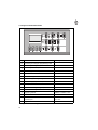
7.2 Keys on the Control Panel
Key
Function
Settings
P
Accessing or exiting the programming mode
E
Confirming a change in a parameter value
+
Increasing the shown parameter value
-
Decreasing the shown parameter value
1
Stitch counting
2
Programming / Working through the seam runs
3
Function key (programmable)
4
Base position of the needle
UP / DOWN
5
Automat. foot lifting during stop in the seam
ON / OFF
6
Automat. foot lifting after thread trimming
ON / OFF
7
Beginning bartack
SINGLE / DOUBLE / OFF
8
End bartack
SINGLE / DOUBLE / OFF
9
Thread trimmer
Thread wiper
ON / OFF
ON / OFF
0
Light barrier function *
ON / OFF
ON / OFF
* = Key function is not assigned in this machine class.
24
7.3 Changing Parameter Values
The changing of parameter values at the operator level occurs via the four green keys
("P", "E", "+", "-") under the display.
In the parameter list on the next page are listed all parameters which can be changed at
the operator level.
1. Accessing the programming mode
- Press the "P" key.
The LED above the key blinks.
It shows that the controls are in the programming mode.
2. Displaying the first parameter of the operator level
- Press the "E" key.
The first parameter with the corresponding parameter value appears in the
display.
Example: "Arv 003"
= Short designation of the parameter
Arv
= Set parameter value
003
3. Changing the parameter value shown
- Increase or decrease the parameter value with the "+" and "-" keys.
If the "+" or "-" key remains pressed the parameter value continues changing until
the key is released.
4. Storing the changed parameter value
- Press the "E" key.
The changed parameter value is stored.
- The next parameter of the operator level appears in the display.
Through repeated pressing of the "E" key, all parameters of the operator level are
called up sequentially.
5. Exiting the programming mode
- Press the "P" key.
The parameter value changed last is stored.
- The controls exit the programming mode.
25
7.4 "Operator Level" Parameter List:
Parameter
Function
Setting
Max.
Min.
Ex works
000 Arv
Beginning bartack stitches-forward
254
0
2
001 Arr
Beginning bartack stitches-reverse
254
0
4
002 Err
End bartack stitches-reverse
254
0
3
003 Erv
End bartack stitches-forward
254
0
3
004 LS
Light barrier compensation stitches *
254
0
4
005 LSF
Number of stitches of the light barrier filter
for knit goods *
254
0
0
006 LSn
Number of light barrier seams *
15
1
1
007 Stc
Number of stitches of a seam with stitch
counting *
254
0
10
5
1
2
255
0
16
008 F
Assignment to key 3 of a
parameter from the technician level
1 = Soft start ON / OFF
2 = Fancy stitch bartack ON / OFF
3 = Stroke adjustment locking = ON
Stroke adjustment tentative = OFF
4 = Needle cooling ON / OFF
5 = Turning back ON / OFF
009 LSI
Sensitivity setting
of the continuous beam light barrier *
010 cLS
PEC compensation stitches with stitch
shortening *
254
0
8
Number of stitches-beginning fancy bartack
forward
254
0
3
Number of stitches-beginning fancy bartack
reverse
254
0
3
082 Ser
Number of stitches-end fancy bartack reverse 254
0
3
083 Sev
Number of stitches-end fancy bartack forward 254
0
3
085 cFW
Number of stitches of the remaining thread
monitor count *
2540
0
0
080 Sav
081 SAR
* = Key function is not assigned in this machine class.
ATTENTION !
Several parameters at the technician level must be
appropriately set for classes 381 and 382.
See Installation Instructions Chapter 6.10.
26
7.5 Key Bank on the Machine Arm
The assignment of the keys of the key bank on the machine arm is dependent on the
class.
1
3
2
4
5
7
Subclass 381 - 160161
381 - 160162
LED
Key
1
8
6
Subclass 382 - 160162
Function
Display: " Sewing Drive Turned On "
Caution Risk of Injury !
With the sewing drive turned on (LED 1 is lit) the
following work may not be conducted:
- Threading the needle and underthreads.
- Changing a bobbin, changing a needle.
- Setting the tension regulator.
- All activities in the motion area of elements.
2
LED display: The next beginning or end bartack will, depending on the setting
of the control panel, be either called up or suppressed
3
Positioning the needle in the high position or low position.
The function of key 3 can be determined with parameter F-144.
1 = Needle high, 2 = Needle high / low, 3 = Single stitch
The factory setting is 1 = Needle high.
4
Manual reverse sewing.
The machine sews in reverse as long as key 4 is pressed.
5
Calling up or suppressing the beginning or end bartack.
If beginning or end bartacking is generally turned on, then
an operation of the switch will suppress the next bartack.
If beginning or end bartacking is generally turned off, then
an operation of the switch will call up the next bartack.
6
Key without function.
7
LED display: Top feed roller raised.
8
Raising or lowering the top feed roller.
27
8. Sewing
The description of sewing assumes the following preconditions:
–
The following functions are set at the control panel:
Beginning bartack: ON
–
–
End bartack: ON
Sewing foot position before and after trimming:
LOW
Needle position before trimming:
LOW (position 1)
Main switch turned on.
The last sewing procedure was completed with end bartack and thread trimming.
Operation and function sequence during sewing:
1
Sewing procedure
2
3
4
Operation / Remarks
Before the sewing start
Initial position
- Pedal in rest position.
Sewing machine is idle.
Needle up. Sewing feet down.
Position the material at the
seam beginning
- Step back on the pedal.
The sewing feet rise.
- Position the material.
- Release the pedal.
The sewing feet lower onto the material.
At the seam beginning
Beginning bartack and
continue sewing
- Step forward on the pedal and hold down.
The beginning bartack is sewn.
Subsequently the machine continues
sewing at the speed determined with the pedal.
Beginning bartack is not to be
sewn
- Press key 3 (bartack suppression).
- Step forward on the pedal.
- The machine sews at the speed determined
with the pedal.
28
Sewing procedure
Operation / Remarks
In the seam middle
Interrupting the sewing
procedure
- Release the pedal (rest position) .
The machine stops in the first position
(needle down).
The sewing feet are down.
Continuing the sewing
procedure
(after release of the pedal)
- Step forward on the pedal.
The machine sews at the speed determined
with the pedal.
The beginning bartack is not sewn.
Sewing a corner
- Release the pedal.
The machine stops in the first position
(needle down).
The sewing feet are down.
- Turn the needle bar right or left off.
- Conduct the required stitches with the second
needle bar.
- Step half back on the pedal
- Turn the material around the needle.
Only one needle may be in the material.
- The sewing feet lower.
Sew the necessary stitchs.
- Turn the needle bar on again.
Sewing an intermediate bartack
- Press key 2 and hold the pedal down.
The machine sews in reverse as long as key 2
is pressed.
The speed is determined by the pedal.
At the seam end
Removing the material
- Step the pedal completely back and hold down.
The end bartack is sewn.
The thread is trimmed.
The machine stops in the second position.
The sewing feet are raised.
End bartack is not to be sewn
- Press key 3 (bartack suppression).
Step the pedal completely back.
The end bartack is not sewn.
The thread is trimmed.
The machine stops in the second position.
The position of the sewing feet is
dependent on press key 6 on the control panel:
a) ON:
- Sewing feet raised.
b) OFF:
- Sewing feet down.
29
9. Maintenance
Caution Risk of Injury !
Turn the main switch off!
The maintenance of the sewing machine may only occur
when it is turned off.
The maintenance work must occur at the latest as per the maintenance intervals listed
in the tables (see column "Operating Hours").
When working very linty materials, shorter maintenance intervals may result.
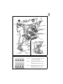
9.1 Cleaning and Inspection
A clean sewing machine protects against malfunctions!
6
4
8
2
10
1
2
3
30
Maintenance work
to be conducted
Remarks
Operating
hours
Machine head
- Remove sewing dust,
thread and cutting residue.
Areas to be particularly cleaned:
- Underside of the needle plate
- Feed dog ridges
- Area around the hook
- Bobbin case
- Thread trimmer
- Area around the needles
- Clean the oil baffle
(under the machine head).
- Remove sewing dust and cutting residue
8
40
Sewing drive
- Check condition and
tension of the V-belt.
The V-belt 1 must be able to be pressed
in approx. 10 mm with a finger at the
center.
160
Pneumatic system
- Check the water level in
the pressure regulator.
The water level should not rise up to the
filter insert 1.
- Blow water out of the water separator 2
under pressure after screwing in the
drain screw 3.
40
Note:
The water separator 2 is equipped with
a semiautomatic condensation drain.
After exceeding a specific pressure, the
condensation is drained automatically.
- Clean the filter insert.
Dirt and condensation are removed
through filter insert 1.
- Separate the sewing unit from the
compressed air supply.
- Screw in drain screw 3.
The pneumatic system of the sewing
unit must be pressure-free.
- Screw off the water separator 2.
- Remove the filter insert 1.
Wash out the dirty filter bowl and filter
insert with naphtha (no solvents!)
and blow clean.
- Reassemble andconnect the
maintenance unit.
500
31
v a r i o c o n t r o l
7 2 0
E
+
6
5
4
P
1
0
9
8
7
2
3
1
3
2
4
32
9.2 Oil Lubrication
Caution Risk of Injury !
Oil can cause skin rashes.
Avoid longer skin contact.
After contact wash yourself thoroughly.
ATTENTION !
The handling and disposal of mineral oils is subject to legal
constraints.
Deliver used oil to an authorized reception point.
Protect your environment.
Take care not to spill any oil.
For lubrication of the special sewing machine use only ESSO SP-NK 10 lubricating oil
or an equivalent oil with following specification:
–
–
Viscosity at 40° C :
10 mm/s
Flash point:
150 °C
ESSO SP-NK 10 is available from DÜRKOPP-ADLER AG sales offices under the
following parts no.s:
2 liter container:
9047 000013
5 liter container:
9047 000014
Lubrication of the machine head
–
Check the reservoir 1 weekly.
The oil level should not drop below the "MIN" marker line.
If necessary, fill oil through the hole in the viewing glass up to the "MAX" marker
line.
Lubrication of the hook
–
The hook run must be lubricated often daily.
Supply lubricating points 2 + 3 often during the day with a few drops of oil.
–
The felt 4 under the hook drives is to be checked weekly.
If necessary, supply the felt 4 with oil at the open right and left corners.
33
10. Optional Equipment
10.1 Thread Wiper
If, at the beginning of a seam, the needle thread end is to be drawn through on the
underside of the material, then it should not get clamped in between the sewing foot
and the material. The thread wiper assures that the needle thread end hangs out of the
needle eye loosely.
The movement of the thread wiper occurs after the trimming of the thread before the
feet are lifted.
Note
The thread wiper can be turned on and off at the control panel.
34