1
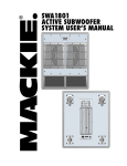
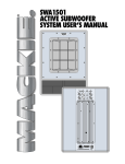
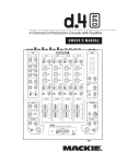
SRM450v2 Active Sound Reinforcement SPEAKEr USer’s manual IMPORTANT SAFETY INSTRUCTIONS 1. Read these instructions. 2. Keep these instructions. 3. Heed all warnings. 4. Follow all instructions. 5. Do not use this apparatus near water. 6. Clean only with a dry cloth. 7. Do not block any ventilation openings. Install in accordance with the manufacturer’s instructions. 8. Do not install near any heat sources such as radiators, heat registers, stoves, or other apparatus (including amplifiers) that produce heat. 9. Do not defeat the safety purpose of the polarized or grounding-type plug. A polarized plug has two blades with one wider than the other. A grounding-type plug has two blades and a third grounding prong. The wide blade or the third prong are provided for your safety. If the provided plug does not fit into your outlet, consult an electrician for replacement of the obsolete outlet. 10.Protect the power cord from being walked on or pinched particularly at plugs, convenience receptacles, and the point where they exit from the apparatus. 11.Only use attachments/accessories specified by the manufacturer. 12.Use only with a cart, stand, tripod, bracket, or table specified by the manufacturer, or sold with the apparatus. When a cart is used, use caution when moving the cart/apparatus combination to avoid injury from tip-over. 13.Unplug this apparatus during lightning storms or when unused for long periods of time. 14.Refer all servicing to qualified service personnel. Servicing is required when the apparatus has been damaged in any way, such as powersupply cord or plug is damaged, liquid has been spilled or objects have fallen into the apparatus, the apparatus has been exposed to rain or moisture, does not operate normally, or has been dropped. 15.Do not overload wall outlets and extension cords as this can result in a risk of fire or electric shock. 16.This apparatus shall not be exposed to dripping or splashing, and no object filled with liquids, such as vases or beer glasses, shall be placed on the apparatus. 17.This apparatus has been designed with Class-I construction and must be connected to a mains socket outlet with a protective earthing connection (the third grounding prong). 18.The MAINS plug or an appliance coupler is used as the disconnect device, so the disconnect device shall remain readily operable. PORTABLE CART WARNING CAUTION AVIS RISK OF ELECTRIC SHOCK. DO NOT OPEN RISQUE DE CHOC ELECTRIQUE. NE PAS OUVRIR CAUTION: TO REDUCE THE RISK OF ELECTRIC SHOCK DO NOT REMOVE COVER (OR BACK) NO USER-SERVICEABLE PARTS INSIDE. REFER SERVICING TO QUALIFIED PERSONNEL ATTENTION: POUR EVITER LES RISQUES DE CHOC ELECTRIQUE, NE PAS ENLEVER LE COUVERCLE. AUCUN ENTRETIEN DE PIECES INTERIEURES PAR L'USAGER. CONFIER L'ENTRETIEN AU PERSONNEL QUALIFIE. AVIS: POUR EVITER LES RISQUES D'INCENDIE OU D'ELECTROCUTION, N'EXPOSEZ PAS CET ARTICLE A LA PLUIE OU A L'HUMIDITE The lightning flash with arrowhead symbol within an equilateral triangle is intended to alert the user to the presence of uninsulated "dangerous voltage" within the product's enclosure, that may be of sufficient magnitude to constitute a risk of electric shock to persons. Le symbole éclair avec point de flèche à l'intérieur d'un triangle équilatéral est utilisé pour alerter l'utilisateur de la présence à l'intérieur du coffret de "voltage dangereux" non isolé d'ampleur suffisante pour constituer un risque d'éléctrocution. The exclamation point within an equilateral triangle is intended to alert the user of the presence of important operating and maintenance (servicing) instructions in the literature accompanying the appliance. Le point d'exclamation à l'intérieur d'un triangle équilatéral est employé pour alerter les utilisateurs de la présence d'instructions importantes pour le fonctionnement et l'entretien (service) dans le livret d'instruction accompagnant l'appareil. 19.NOTE: This equipment has been tested and found to comply with the limits for a Class B digital device, pursuant to part 15 of the FCC Rules. These limits are designed to provide reasonable protection against harmful interference in a residential installation. This equipment generates, uses, and can radiate radio frequency energy and, if not installed and used in accordance with the instructions, may cause harmful interference to radio communications. However, there is no guarantee that interference will not occur in a particular installation. If this equipment does cause harmful interference to radio or television reception, which can be determined by turning the equipment off and on, the user is encouraged to try to correct the interference by one or more of the following measures: • Reorient or relocate the receiving antenna. • Increase the separation between the equipment and the receiver. • Connect the equipment into an outlet on a circuit different from that to which the receiver is connected. • Consult the dealer or an experienced radio/TV technician for help. CAUTION: Changes or modifications to this device not expressly approved by LOUD Technologies Inc. could void the user's authority to operate the equipment under FCC rules. 20.This apparatus does not exceed the Class A/Class B (whichever is applicable) limits for radio noise emissions from digital apparatus as set out in the radio interference regulations of the Canadian Department of Communications. ATTENTION — Le présent appareil numérique n’émet pas de bruits radioélectriques dépassant las limites applicables aux appareils numériques de class A/de class B (selon le cas) prescrites dans le réglement sur le brouillage radioélectrique édicté par les ministere des communications du Canada. 21.Exposure to extremely high noise levels may cause permanent hearing loss. Individuals vary considerably in susceptibility to noise-induced hearing loss, but nearly everyone will lose some hearing if exposed to sufficiently intense noise for a period of time. The U.S. Government’s Occupational Safety and Health Administration (OSHA) has specified the permissible noise level exposures shown in the following chart. According to OSHA, any exposure in excess of these permissible limits could result in some hearing loss. To ensure against potentially dangerous exposure to high sound pressure levels, it is recommended that all persons exposed to equipment capable of producing high sound pressure levels use hearing protectors while the equipment is in operation. Ear plugs or protectors in the ear canals or over the ears must be worn when operating the equipment in order to prevent permanent hearing loss if exposure is in excess of the limits set forth here: Duration, per day in hours 8 6 4 3 2 1.5 1 Sound Level dBA, Slow Response 90 92 95 97 100 102 105 0.5 110 0.25 or less 115 Typical Example Duo in small club Subway Train Very loud classical music Dave screaming at Steve about deadlines Loudest parts at a rock concert Correct disposal of this product. This symbol indicates that this product should not be disposed of with your household waste, according to the WEEE Directive (2002/96/EC) and your national law. This product should be handed over to an authorized collection site for recycling waste electrical and electronic equipment (EEE). Improper handling of this type of waste could have a possible negative impact on the environment and human health due to potentially hazardous substances that are generally associated with EEE. At the same time, your cooperation in the correct disposal of this product will contribute to the effective usage of natural resources. For more information about where you can drop off your waste equipment for recycling, please contact your local city office, waste authority, or your household waste disposal service. Contents IMPORTANT SAFETY INSTRUCTIONS........................................2 CONNECTIONS.......................................................................10 INTRODUCTION........................................................................4 PLACEMENT............................................................................10 HOOKUP DIAGRAMS...............................................................6 Room Acoustics..............................................................10 Quick Start.......................................................................6 RIGGING...............................................................................11 REAR PANEL DESCRIPTION.......................................................8 THERMAL CONSIDERATIONS..................................................12 1. IEC Socket.....................................................................8 AC POWER CONSIDERATIONS...............................................12 2. POWER Switch.............................................................8 AC Power Distribution....................................................12 3. POWER ON Indicator...................................................8 SERVICE INFORMATION.........................................................14 4. TIMED TURNOFF...........................................................8 Troubleshooting..............................................................14 5. THERMAL Indicator.......................................................8 Repair.............................................................................16 6. CONTOUR....................................................................8 CARE AND MAINTENANCE.....................................................16 7. LOW CUT......................................................................8 SPECIFICATIONS.....................................................................17 8. LEVEL............................................................................9 BLOCK DIAGRAM...................................................................18 9. SIGNAL PRESENT Indicator...........................................9 LIMITED WARRANTY...............................................................19 10. PEAK Indicator...........................................................9 11. INPUT Connector........................................................9 12. THRU Connector.........................................................9 Please write the serial number for your SRM450v2 here (or for both SRM450v2s if you have two) for future reference (i.e., insurance claims, tech support, return authorization, etc.): Loudspeaker 1 Loudspeaker 2 Purchased at:___________________________________ Date of Purchase:_____________ Don’t forget to visit our website at www.mackie.com for more information about this and other Mackie products. Part No. SW0617 Rev. D 02/09 ©2007-2009 LOUD Technologies Inc. All Rights Reserved. INTRODUCTION Thank you for choosing LOUD Technologies’ Mackie active sound reinforcement loudspeakers. The SRM450v2 is a redesigned version of our popular SRM450 active loudspeaker. With its newly designed ClassD Fast-Recovery amplifiers, high-output compression driver, and new 12" neodymium woofer, it produces an even smoother sound than the original. SRM means Sound Reinforcement Monitor, and the SRM450v2 truly produces a studio quality sound in a sound reinforcement speaker. Our design goal was to build a sound reinforcement speaker with: 1. High precision, high output, and accurate playback. 2. Very wide, smooth dispersion of mid and high frequencies. 3. Ergonomically correct physical design for easy transport and set up. Through the combined resources of our top-notch mechanical and analog engineers, and our experienced transducer engineers at EAW, we were able to achieve our design goals in every aspect. The result is a sound reinforcement system equally at home in a concert setting, in the studio, impromptu concerts on the studio roof, in the cinema, or in a home theater. • Each amplifier has its own compressor circuit that acts when the input signal is large enough to cause clipping, distortion and excessive voice coil heat. The compressor will automatically decrease the input signal to a safe level. The compressor in the low-frequency amp works independently from that in the high-frequency amp. • The low-frequency amp uses a servo feedback loop which senses the current flowing in the woofer coil. This controls the low-frequency response and maintains low distortion at high output levels. • The low-frequency amplifier also has a sweeping filter. This will automatically move the low cut-off frequency up or down depending on the amplifier output. For example, if the amplifier is below clipping, the low-frequency cutoff point is 55 Hz. As it approaches clipping, this shifts up smoothly to 120 Hz, providing more power reserves and less distortion before clipping. This happens quickly and continuously, protecting the amplifier and the woofer and reducing any noticeable distortion. Warning: Although the amplifiers have these protection circuits, you must still make sure the PEAK light is not blinking continuously. If it is, turn down your mixer faders, or preamplifier gain, or turn down the SRM450v2 LEVEL control. The Transducers The SRM450v2 active speakers feature a 12-inch highpower low-frequency woofer with a 3-inch voice coil and neodymium magnet, and a 1.75-inch titanium diaphragm high-output ceramic compression driver. This high-frequency driver is mounted on an acoustically non-resonant exponential waveguide, providing a wide, controlled dispersion and precise reproduction of the critical upper mid-range and high frequencies. The result is an unbelievably smooth off-axis response that allows everyone in the audience to experience the same high-resolution audio no matter where they are seated. FR Series Power Amplifiers To power these beauties, each SRM450v2 includes two of our acclaimed FR Series “Fast Recovery” power amplifiers. In addition, the low-frequency amplifier uses a Class D design for improved efficiency and cleaner power. Our exclusive designs use low negative feedback, yet allow the amplifiers to maintain low distortion and stability and to quickly recover when driven into clipping. The amplifiers include the following features: • The low-frequency amplifier produces up to 540 watts peak (300 continuous) before clipping. • The high-frequency amplifier produces up to 150 watts peak (100 continuous) before clipping. The Crossover The built-in electronic crossover is a 24 dB/octave Linkwitz-Riley design. Although more expensive than other crossover designs, the benefits provided by the LinkwitzRiley design have been well documented. These benefits include: • Absolutely flat frequency response throughout the bandpass, without the characteristic ripple near the crossover point exhibited by other designs. • The sharp 24 dB per octave roll-off of the filters ensures that the transducers aren’t reproducing frequencies outside of their capabilities. • The acoustic sum of the two driver responses is unity at the crossover frequency, resulting in perfect power response. • Our heroic engineers have worked carefully to ensure that the SRM450v2 also provides perfect phase response. This diligence has yielded phenomenal accuracy, even if you are standing 20 feet away. The Cabinet The SRM450v2 cabinet was designed to be the strongest molded composite cabinet on the planet. This material is as strong as concrete, and rigid enough to prevent unwanted vibrations in the cabinet. It has built-in fly points for hanging, and a socket in the bottom for mounting on a tripod stand. Although it is an exceptional choice for installed sound situations, its light weight and durable finish also make it ideal for portable sound system use. The asymmetrical trapezoidal design of the cabinet makes it easy to use as a floor wedge for stage monitor applications. The Active Advantage There are a number of advantages to using an active speaker system over a passive loudspeaker: • The internal crossover is active, and its low power circuitry operates on line-level signals. It does not waste speaker-level power like a passive crossover with large coils, caps, and resistors. • The input signals are crossed over before they reach the amplifiers, so each amplifier only receives the correct frequency range for its driver. • The amplifiers are designed specifically for these speaker load impedances. There is no guesswork as to what load each amplifier has to drive, so they can provide maximum acoustic output from the speakers, yet minimize the danger of speaker damage due to overdriving a lesser amplifier. • The connecting wires between the amplifier outputs and the drivers are kept to a minimum, so the damping factor of the amplifier isn’t compromised by the resistance of long speaker cables. In addition, all the power from the amplifier is transferred directly to the drivers with no speaker cable losses. • The acoustic sum of the outputs from the two drivers is optimized electronically, as well as physically, so the amplitude response is flat and there is no lobing error. • The presence of active circuits within the speaker cabinet allow the designer to add on extra details, such as a high quality mic/line input section. In short, all the complex interconnected components in the system are designed to work in harmony with each other to produce the best possible sound. (Even for Uncle Bert’s star performance on spoons!) HOOKUP DIAGRAMS Quick Start 1. Start with the following settings on the back of the SRM450v2: Turn the POWER switch off (down). Set the TIMED TURNOFF, CONTOUR, and LOW CUT switches out. WARNING: Turn the LEVEL control down (counterclockwise) before every use. If not, you could be in for a startling surprise, especially if the last time you used it was with a microphone and now you want to connect a line-level source. 2. Connect the output from your signal source (mixing console, microphone, preamp, or other mic- or line-level source) directly to the INPUT connector on the back of the SRM450v2. It accepts balanced line-level signals from mixers, preamplifiers, CD players, tape decks, etc., and accepts direct connections from dynamic microphones. 3. Connect the supplied AC power cord to the IEC socket on the back of the SRM450v2. Plug the other end into an AC outlet properly configured with the correct voltage for your particular model. THERMAL PEAK 4. Turn on your signal source. Make sure its Master Volume control (if it has one) is turned all the way down. 5. Turn on the SRM450v2 POWER switch. 6. Start the signal source, whether it be speaking into a microphone or starting a CD player. Adjust any volume controls on the signal source for normal operation. 7. Slowly turn up the LEVEL control on the back of the SRM450v2 until the desired volume is reached (and the PEAK light does not come on) Always wear hearing protectors if you are close when it is playing at high levels. 8. If there is no sound, always turn down the SRM450v2 LEVEL control before investigating. There may be a mixer or preamplifier mute or tape switch engaged, or a mic switch off. SIGNAL PRESENT THERMAL PEAK NORMAL (+4dBu) POWER ON OFF 100Hz ON 12k/AIR 75Hz CONTOUR +3dB LOW CUT ON OFF MIC LINE TIMED TURNOFF OO 100Hz ON 12k/AIR 75Hz CONTOUR +3dB INPUT PEAK SIGNAL PRESENT THERMAL PEAK NORMAL (+4dBu) POWER 12k/AIR CONTOUR +3dB 75Hz LOW CUT OO SIGNAL PRESENT THERMAL +40dB POWER ON OFF 100Hz ON 12k/AIR OO LOW CUT POWER SIGNAL PRESENT 100Hz ON O 12k/AIR CONTOUR +3dB 75Hz OO LOW CUT THRU ON OFF PEAK POWER SIGNAL PRESENT MIC LINE TIMED TURNOFF +40dB 100Hz ON LEVEL O INPUT 12k/AIR CONTOUR +3dB 75Hz LOW CUT OO +40dB LEVEL Left Line level Output O INPUT PARALLEL THERMAL NORMAL (+4dBu) MIC LINE TIMED TURNOFF +40dB LEVEL THRU PARALLEL INPUT THRU PARALLEL INPUT PARALLEL Next THERMAL PEAK SIGNAL PRESENT THERMAL PEAK NORMAL (+4dBu) POWER ON OFF 100Hz ON 12k/AIR 75Hz CONTOUR +3dB LOW CUT OO SIGNAL PRESENT NORMAL (+4dBu) ON OFF MIC LINE TIMED TURNOFF POWER MIC LINE TIMED TURNOFF +40dB 100Hz ON LEVEL O 12k/AIR CONTOUR +3dB 75Hz LOW CUT INPUT PARALLEL NORMAL (+4dBu) 75Hz CONTOUR +3dB ON OFF MIC LINE TIMED TURNOFF LEVEL O THRU PEAK NORMAL (+4dBu) MIC LINE 100Hz ON OO Right Line level Output Next +40dB LEVEL O THRU INPUT THRU PARALLEL INPUT PARALLEL Thru Thru Mixer or Preamplifier PREMIUM ANALOG MIXER w/ PERKINS EQ & FIREWIRE OPTION PREMIUM ANALOG MIXER w/ PERKINS EQ & FIREWIRE OPTION 1 2 3 4 5 6 7 8 9 10 11 12 1 2 3 4 5 6 7 8 9 10 11 12 Daisy-chaining SRM450 v2s SRM450v2: STEREO OPERATION WITH A MIXER, and using the thru jack +40dB LEVEL THRU PARALLEL THERMAL OO LOW CUT O THRU TIMED TURNOFF MIC LINE TIMED TURNOFF +40dB LEVEL O ON OFF SIGNAL PRESENT NORMAL (+4dBu) POWER For microphone connections, you can daisychain up to two SRM450v2s using the THRU jacks as shown. Take great care to point any microphones away from the SRM450v2s, otherwise you may get feedback. THERMAL PEAK Dynamic Microphone SIGNAL PRESENT THERMAL PEAK NORMAL (+4dBu) ON OFF POWER 100Hz ON 12k/AIR CONTOUR +3dB 75Hz LOW CUT OO POWER ON OFF MIC LINE TIMED TURNOFF SIGNAL PRESENT NORMAL (+4dBu) 100Hz ON LEVEL O MIC LINE TIMED TURNOFF +40dB 12k/AIR CONTOUR +3dB 75Hz OO LOW CUT +40dB LEVEL O THRU INPUT THRU PARALLEL INPUT PARALLEL THRU Output SRM450v2: USING A MICROPHONE AND THE THRU JACK The SRM450v2 can be used with a Mackie SWA1501 (or SWA1801z or SWA2801z) subwoofer to create an incredibly powerful system. The active crossover inside the SWA1501 splits the fullrange input signal into two ranges. The SWA1501 plays the low-frequency range through its 500 watt amplifier and 15-inch woofer, and sends the high-pass range to the SRM450v2. The SRM450v2 can be pole mounted on top of the SWA1501 as shown using the optional SPM100 Speaker Pole Mount, saving the cost of a more expensive tripod stand. Pole Mount Line-level Hi-pass out Pole Mount Power Cord Line-level Hi-pass out ACTIVE Full Range Power Cord ACTIVE Full Range PREMIUM ANALOG MIXER w/ PERKINS EQ & FIREWIRE OPTION Power Cords Power Cords 1 2 3 4 5 6 7 8 9 10 11 12 SWA1501 plays the low frequencies SWA1501 plays the low frequencies SRM450v2: 3-Way system WITH A POWERED SUBWOOFER REAR PANEL DESCRIPTION The SRM450v2 has several connectors, controls, and indicators that you should understand. 1. IEC Socket This is where you connect the supplied AC linecord to provide AC power to the SRM450v2’s built-in power amplifiers. Plug the linecord into an AC socket properly configured for your particular model. Note: If you happen to lose the AC linecord, replacements are readily available at any office or computer supply store. Always use a three-pin plug with a ground pin. 5. THERMAL Indicator This LED lights if the heatsink temperature exceeds a safe operating temperature and triggers the thermal safety switch. In the unlikely event that this occurs, the built-in amplifiers shut down until the heatsink temperature cools back down. Then the thermal switch resets itself, the THERMAL indicator turns off, and normal operation resumes. If the SRM450v2 keeps shutting down, make sure there is plenty of ventilation to the rear panel. Please see “Thermal Considerations” on page 12. 2. POWER Switch Switch up to turn the SRM350v2 on. Make sure the LEVEL control is down before you turn it on. Press the bottom of this switch to put the speaker into standby mode. It will not function, but the circuits are still live. To remove AC power, either turn off the AC mains supply, or unplug the power cord from the speaker and the AC mains supply. 3. POWER ON Indicator When the POWER switch is turned on, and the linecord is connected to an active AC Mains supply, this indicator, located just above the POWER switch, glows to let you know that you’re ready to rock and roll. The cool blue LED on the front of the speaker works in the same way. 4. TIMED TURNOFF When this switch is pushed in, the built-in amplifiers turn on and off depending on the presence or absence of an input signal. An input signal level of –45 dBu (minimum) activates the auto-on function. A silent period greater than three minutes activates the auto-off function. The blue LED on the front of the speaker reflects the state of the amplifiers. 6. CONTOUR Pushing in this switch engages a filter that provides 3 dB of boost to the low and high frequencies (below 100 Hz and above 12 kHz). This provides a punchy, crisp sound for most live music applications. You can experiment with this switch by leaving it out for a while, then pushing it in to determine which way sounds best for your application. It is especially useful when listening at lower volumes, as it highlights the bass like a Loudness switch, in addition to boosting the highs. 7. LOW CUT Pushing in this switch engages a low-cut filter, which rolls off the low frequencies below 75 Hz. This is useful for minimizing stage noise (rumble) and microphone handling noise. It is highly recommended that you engage this switch when using the SRM450v2 as a stage monitor. This allows the bass amplifier to utilize its power for those frequencies useful in stage monitor applications. THERMAL PEAK SIGNAL PRESENT NORMAL (+4dBu) ON OFF POWER MIC LINE TIMED TURNOFF 100Hz ON 12k/AIR CONTOUR +3dB 75Hz LOW CUT OO +40dB LEVEL O THRU INPUT PARALLEL 8. LEVEL 11. INPUT Connector This is used to adjust the signal level going into the built-in power amplifiers, from off, up to 40 dB of gain. Since the SRM450v2 incorporates Mackie’s world-class low-noise mic preamp technology, you can connect either a line-level or a microphone-level signal to the input, and use this control to adjust the level correctly. There is no phantom power for a microphone, so you should use a dynamic mic, or use a condenser type if it has its own battery power. This is a female XLR-type connector that accepts a balanced or unbalanced mic- or line-level signal. 12. THRU Connector This is a male XLR-type connector that produces exactly the same signal that is connected to the INPUT jack. It can be a balanced or unbalanced mic- or line-level signal. Use it to daisy-chain several active speakers together off the same signal source. Follow the Quick Start guide on page 6 for setting the LEVEL control. For most applications, it will be in the NORMAL position (12 o’clock). If you have a particularly high line-level signal connected to the SRM450v2, you may need to turn the control down to the LINE indication (9 o’clock). If you have a low line-level or mic-level signal connected, you may need to turn the LEVEL control up to the MIC indication (3 o’clock). 9. SIGNAL PRESENT Indicator This LED illuminates whenever there is a signal present at the INPUT connector on the rear panel. It senses the signal just prior to the LEVEL control, so even if the LEVEL control is turned down, the SIGNAL PRESENT indicator still works, letting you know there is a signal present at the input before turning up the LEVEL control. 10. PEAK Indicator When the signal levels at the amplifier outputs approach clipping, a soft compression circuit is activated that reduces the input signal. The PEAK LED lights whenever the compression circuit is active. At this time, the SRM450v2 may reach sound pressure levels of 120 dB or more. It’s okay for the PEAK indicator to blink occasionally, but if it blinks frequently or continuously, either turn down the signal level at the mixer or other signal source, or turn down the SRM450v2’s LEVEL control. Wear hearing protection if you are close to the SRM450v2 playing at high levels. CONNECTIONS PLACEMENT The SRM450v2 has a female XLR input that accepts a balanced or unbalanced mic- or line-level signal. When connecting a balanced signal, be sure it’s wired per AES (Audio Engineering Society) standards: XLR Hot (+) Pin 2 Cold (–) Pin 3 Shield (Ground) Pin 1 The SRM450v2 active speakers are designed to sit on the floor, a tabletop, or to fit on a standard tripod speaker stand. They can also be suspended by the rigging points, shown opposite. You can lay the cabinet down on its side and use the SRM450v2 as a floor monitor. The asymmetrical trapezoidal shape of the cabinet provides a perfect angle for aiming up toward performers from the front of the stage. When used for monitor applications, we recommend engaging the LOW CUT filter. There is also a male XLR connector labeled THRU. This allows you to connect more than one SRM450v2 to the output of your mixing console. Simply plug the signal source output into the first INPUT jack, and patch that speaker’s THRU jack to the next INPUT jack, and so on, daisy-chaining multiple speakers (see diagram on page 6). There is a limit to how many you can daisy-chain together. A general rule is to maintain a load impedance ten times or more than the source impedance to prevent excessive loading on the source. For example, if your mixer has an output impedance of 120 ohms, then you can daisy chain up to sixteen SRM450v2s. This is a load of 1250 ohms (SRM450v2 input impedance=20 kohms; 16 of these in parallel=1250 ohms). Since microphones typically have a higher output impedance, you should limit daisy-chaining from a mic source to two SRM450v2s (see the diagram on page 7). The THRU jack is wired straight from the INPUT connector — there is no electronic circuitry between — so the signal coming out of the THRU jack is exactly the same as the signal going in. As with any powered components, protect them from moisture. If you are setting them up outdoors, make sure they are under cover if you expect rain. The SRM450v2 generates magnetic fields. Do not place it closer than two feet (0.6 meters) from any TV set or computer monitor. Check the screen for any change in color or distortion. Do not place any magnetic audio or video tapes or computer discs near the SRM450s. Room Acoustics The SRM450v2 active speakers are designed to sound as neutral as possible; that is, to reproduce the input signal as accurately as possible, monitoring the sound rather than changing it. Room acoustics play a crucial role in the overall performance of a sound system. However, the wide highfrequency dispersion of the SRM450v2 helps to minimize the problems that typically arise. Balanced XLR Connectors Top 900 900 Dispersion up to 20 kHz 10 RIGGING Here are some other placement tips: • Avoid placing loudspeakers in the corners of a room. This increases the low-frequency output and can cause the sound to be muddy and indistinct. • Avoid placing loudspeakers against a wall. This, too, increases the low frequency output, though not as much as corner placement. However, if you do need to reinforce the low frequencies, this is a good way to do it. • Avoid placing the active speakers directly on a hollow stage floor. A hollow stage can resonate at certain frequencies, causing peaks and dips in the frequency response of the room. It’s better to place the active speakers on a sturdy table or tripod stands. • Position the active speakers so the high-frequency drivers are two to four feet above ear level for the audience (make allowances for a standing/dancing in the aisles audience). High frequencies are highly directional and tend to be absorbed much easier than lower frequencies. By providing direct line-of-sight from the active speakers to the audience, you increase the overall brightness and intelligibility of the sound system. • Highly reverberant rooms, like many gymnasiums and auditoriums, are a nightmare for sound system intelligibility. Multiple reflections off the hard walls, ceiling, and floor play havoc with the sound. Depending on the situation, you may be able to take some steps to minimize the reflections, such as putting carpeting on the floors, closing draperies to cover large glass windows, or hanging tapestries or other materials on the walls to absorb some of the sound. However, in most cases, these remedies are not possible or practical. So what do you do? Making the sound system louder generally doesn’t work because the reflections become louder, too. The best approach is to provide as much direct sound coverage to the audience as possible. The farther away you are from the speaker, the more prominent will be the reflected sound. Use more speakers strategically placed so they are closer to the back of the audience. If the distance between the front and back speakers is more than about 100 feet, you should use a delay processor to time-align the sound. (Since sound travels about 1 foot per millisecond, it takes about 1/10 of a second to travel 100 feet). The SRM450v2 cabinets are fitted with ten rigging points as shown in the diagram below. These are M10 inserts. M10 threaded eyebolts (M10 x 1.5 mm x 20 mm) are available to fit these inserts (PA-A1 Eyebolts). WARNING: Never attempt to suspend the SRM450v2 active speakers by their handles. If you want to suspend them, use the rigging points only. Consult a professional rigger or structural engineer prior to suspending loudspeakers from a structure not intended for that use. Always know the working load limit of the structure supporting the loudspeaker array. Always make sure that the rigging hardware minimum rating is at least five times the actual load. Back Both Sides SRM450 Pole Mount Top Rigging Points Bottom If you are hanging them in an inaccessible place, such as over a lion’s cage, make sure that you first complete the sound check and set the SRM450v2 LEVEL correctly. Also set the TIMED TURNOFF switch if you want the SRM450v2 to turn on when there is a signal present. It will also turn off after three or more minutes of silence. 11 THERMAL CONSIDERATIONS The amplifiers inside the SRM450v2s are convection cooled by a large heatsink. For efficient cooling, it is important to allow at least six inches of free space behind the SRM450v2. If you use the SRM450v2 on its side for stage monitor applications, we highly recommended that you engage the rear panel LOW CUT switch. This will allow more power for useful monitor frequencies, while reducing the possibility of overheating. AC POWER CONSIDERATIONS Be sure the SRM450v2 is plugged into an outlet that is able to supply the correct voltage specified for your model. If the voltage should drop below 97% of the specified line voltage, the built-in amplifiers will no longer be able to supply rated power. (They will continue to operate down to 75% of the rated line voltage, but won’t reach full power, resulting in lower headroom). Under maximum SPL conditions, where musical peaks are clipping, the SRM450v2 120V model draws 2.5 amps on average (1.3 amps for the 240V model). Under normal conditions, the current draw is below 1 amp. We recommend that a stiff (robust) supply of AC power be used because the amplifiers place high current demands on the AC line. The more power that is available on the line, the louder the speakers will play and the more peak output power will be available for cleaner, punchier bass. A suspected problem of “poor bass performance” is often caused by a weak AC supply to the amplifiers. AC Power Distribution If the ambient temperature in the room is high, though highly unlikely, it could cause the amplifiers to overheat. In this case, you should try aiming a fan at the heatsink to increase the air flow through the fins. During a performance, don’t have it cranked so high that the rear panel PEAK LED is blinking frequently or lighting continuously. You should turn down the LEVEL control a notch or two to avoid overheating the amplifiers or your neighbors. If the amplifiers do overheat, a built-in thermal switch will activate, placing the amplifiers into standby. When the amplifiers have cooled down to a safe operating temperature, the thermal switch will reset and the SRM450v2 will resume normal operation. ACTIVE SOUND REINFORCEMENT SYSTEM LOW CUT HEATSINK A 240 VAC center-tapped service entrance transformer serves the majority of AC outlets encountered in homes and clubs (in the U.S.). This provides two phases of AC power on either side of the center tap, at 120V each. If lighting is used in a show, it is preferable to power the lights from one leg of the service, and power the audio equipment from the other leg. This will help minimize noise from the lights coupling into the audio (particularly if SCRs, or light-dimmer switches, are used). Wherever possible, connect all of your equipment to the same electrical circuit. This will help reduce the possibility of a ground loop problem causing an annoying hum in your speakers. Low power components such as tape decks, mixers, effects processors and CD players should be connected to the same outlet as the SRM450v2s. Use fused power strips as shown in the diagram on the next page. Make sure that the total current draw of your components does not exceed the capability of the outlets and power strips. HIGH VOLTAGE POWER LINE THERMAL THERMAL PEAK SIGNAL PRESENT NORMAL (+4dBu) ON OFF POWER 100Hz ON 12k/AIR CONTOUR +3dB 75Hz LOW CUT OO 240V 120V +40dB LEVEL TRANSFORMER O THRU INPUT PARALLEL 12 120V PRIMARY WINDING MIC LINE TIMED TURNOFF PEAK 240V CENTER-TAPPED SECONDARY EARTH GROUND (NEUTRAL) SECONDARY WINDING For the US 120 V model: A maximum of five SRM450v2s can be connected per 15A service. This allows each SRM450v2 to be safely operated at its maximum level. Don’t use an outlet if it is wired improperly! This is to protect yourself as well as your equipment. When turning your system on, turn on the SRM450v2s last. This will stop any turn-on thumps and bangs from your source equipment being amplified. When turning off your system, turn off the SRM450v2s first. This will prevent any turn-off thumps and bangs from your source equipment being amplified. When setting up for a show, often you are plugging into an AC power distribution system you know nothing about. You may even be faced with 2-wire outlets that are missing the third safety ground pin. It’s a good idea to have a three-wire AC outlet tester in your toolbox so you can check the outlets yourself to make sure they are wired correctly. These testers will tell you if the polarity of the hot and neutral wires is reversed and if the safety ground is disconnected. Never remove the ground pin on the power cord of the SRM450v2 or any other component. This is very dangerous. SRM450 SRM450 SRM450v2: AC CONNECTIONS 13 SERVICE INFORMATION If you think your Mackie product has a problem, please check out the following troubleshooting tips and do your best to confirm the problem. Visit the Support section of our website (www.mackie.com/support) where you will find lots of useful information such as FAQs and other documentation. You may find the answer to the problem without having to send your Mackie product away. Troubleshooting No power! • Our favorite question: Is it plugged in? Make sure the AC outlet is live (check with a tester or lamp). • Our next favorite question: Is the POWER switch on? If not, try turning it on. • Is the blue light on the front panel illuminated? If not, make sure the AC outlet is live. If so, refer to “No sound” below. • The AC line fuse inside the chassis is blown. This is not a user-serviceable part. Refer to “Repair” on page 16 to find out how to proceed. No sound! • Is the input LEVEL control turned all the way down? Follow the procedures in the “Quick Start” section on page 6 to verify that all the volume controls in the system are properly adjusted. • Is the signal source working (and making union scale)? Make sure the connecting cables are in good repair and securely connected at both ends. Make sure the output volume (gain) control on the mixing console or preamp is turned up sufficiently to drive the inputs of the speaker. You should be able to see the SIGNAL PRESENT LED blink on the rear panel. • Make sure the preamp or mixer does not have a Mute on, or a Tape or Processor loop engaged. If you find something like this, make sure the volume/gain is turned down before disengaging the offending switch. • Is the THERMAL LED lit? Make sure there is at least six inches of free space behind the heatsinks. Allow the SRM450v2 to cool off and it will turn back on. 14 One side is way louder than the other! • Are the LEVEL controls set the same on both active speakers? • Check the PAN control or balance on the signal source. It may be turned too far to one side. If you’re using a stereo signal source, it may be delivering an out-ofbalance stereo signal. • Try swapping sides: Turn off the active speakers, swap the input cables coming from the mixing console, turn the active speakers back on. If the same side is still louder, the problem may be with your active speakers or cables between the mixer and the active speaker. If the other side is louder now, the problem is with the mixer or the signal source. Poor bass performance • Check the polarity of the connections between the mixer/preamp and the active speakers. You may have your positive and negative connections reversed at one end of one cable, causing one SRM450v2 to be out-ofphase. As soon as the music gets loud, the SRM450v2 shuts down! • Be sure that the PEAK LED on the rear panel is not lighting up frequently or continuously. Remember to wear ear protectors if you get close to an SRM450v2 playing at high levels. When the PEAK LED comes on, the SPL is in a region above 120 dB!!! • Make sure there is room behind the rear panel to provide sufficient ventilation to the heatsink. Bad sound! • Is it loud and distorted? Follow the procedures described in the “Quick Start” section to verify that the levels are set properly. • Is the input connector plugged completely into the jack? Be sure all connections are secure. It’s a good idea to periodically clean all electrical connections with a non-lubricating electrical contact cleaner. Noise • Make sure all connections to the active speakers are good. • Make sure none of the signal cables are routed near AC cables, power transformers, or other EMI-inducing devices. • Is there a light dimmer or other SCR-based device on the same AC circuit as the SRM450v2? Use an AC line filter or plug the SRM450v2 into a different AC circuit. • Disconnect any cables which come in from outside, such as cable TV, satellite TV or roof top antennas. They must be disconnected from every part of your system, such as the TV, VCR and preamp. If the hum goes away, you can add a “ground loop isolator” in your cable line. This is an inexpensive device available from video or TV dealers, or you can make your own from two TV baluns (standard TV 75/300 ohm adapters): Hum • Turn the LEVEL control all the way down. If the noise disappears, it’s coming from the signal source. If not, try disconnecting the cable connected to the INPUT jack. If the noise disappears, it could be a “ground loop,” rather than a problem with the SRM450v2. Try some of the following troubleshooting ideas: • Use balanced connections throughout your system for the best noise rejection. • Whenever possible, plug all the audio equipment’s linecords into outlets which share a common ground (see the diagram on page 13). The distance between the outlets and the common ground should be as short as possible. Never remove the ground pin on the power cord of the SRM450v2 or any other component. This is very dangerous. • The hum may appear when using an unbalanced source (consumer preamp, CD player, VCR, etc.). This is caused by the unbalanced-to-balanced interface between the devices (and exacerbated by the fact that most consumer audio equipment have a two-wire linecord, without the third-pin safety ground). Use an interconnect cable wired as shown below. The important point is that the shield and the wire from the XLR pin 3 are joined at the RCA (source) end. RCA 3-Conductor Cable Balun join (+insulate) Balun The baluns are threaded at one end (75 ohm) to fit TV coax cable and have two wires at the other end (300 ohm). They will not affect the video quality. • If the hum persists, try removing components one at a time from the back of the mixer or preamplifier, and check for hum each time (turn off your equipment before you undo any connections). It is fairly common to find more than one problem. • If your preamp or mixer are the only things connected to the SRM450v2s and the hum is still there, try different connection cables, or move the preamp/mixer to another location. • Pressing the LOW CUT FILTER may help reduce the hum if you have trouble finding the cause of the problem. Do this anyway if you do not need to reproduce the lower frequency range. XLR 2 1 3 shield 15 Repair drivers are located. For warranty service, refer to the warranty information on page 19. Dimensions 15.4 in/390 mm CARE AND MAINTENANCE 14.8 in/376 mm If you do not have access to our website, you can call our Tech Support department at 1-800-898-3211, Monday-Friday, normal business hours, Pacific Time, to explain the problem. Tech Support will tell you where the nearest factory-authorized service center is located in your area. 26.0 in/660 mm Non-warranty service for Mackie products is available at a factory-authorized service center. To locate your nearest service center, visit www.mackie.com, click “Support” and select “Locate a Service Center.” Service for Mackie products living outside the United States can be obtained through local dealers or distributors. 14.8 in/376 mm Your Mackie active speakers will provide many years of reliable service if you follow these guidelines: 15.4 in/390 mm Avoid exposing the loudspeakers to moisture. If they are set up outdoors, be sure they are under cover if you expect rain or you live in Washington. • Avoid exposure to extreme cold (below freezing temperatures). If you must operate the loudspeakers in a cold environment, warm up the voice coils slowly by sending a low-level signal through them for about 15 minutes prior to high-power operation. • Use a dry cloth to clean the cabinets. Only do this when the power is turned off. Avoid getting moisture into any of the openings of the cabinet, particularly where the Need help with your new SRM450v2? • Visit www.mackie.com and click Support to find: FAQs, manuals, addendums, and other useful information. • Email us at: [email protected]. • Telephone 1-800-898-3211 to speak with one of our splendid technical support representatives, (Monday through Friday, normal business hours, PST). 16 SRM450v2 SPECIFICATIONS System Specifications Line Input Power Frequency Response (–3 dB) 55 Hz – 18 kHz Frequency Range (–10 dB) 45 Hz – 20 kHz Directivity Factor; Q (DI)9.95 (9.98), averaged 2 kHz to 10 kHz Max SPL Long-term @ 1m 124 dB Max SPL Peak @ 1m 127 dB Crossover Linkwitz-Riley, 24 dB/octave @ 1600 Hz Audio Input Type Balanced Differential Input Impedance20 kohms Input Protection RFI and level protected Sensitivity Line: +4 dBu (center detent) Mic: –36 dBu Maximum Input Level +22 dBu Low-Cut Frequency 75 Hz, Second-order filter Acoustic Contour Equalization Peaking: +3 dB @ 100 Hz, +3 dB @ 12 kHz Operating Temperature Range –10ºC to 45ºC (14ºF to 113ºF) Power Amplifiers Low-Frequency Power Amplifier Rated Power300 watts* Rated THD < 0.1% Cooling Convection Extrusion Design Class D, Parametric Servo Feedback High-Frequency Power Amplifier Rated Power 100 watts* Rated THD < 0.1% Cooling Convection Extrusion Design Conventional Class AB *Rated power is continuous rms wattage into transducer’s rated impedance @ 5 kHz for the HF amplifier and @ 500 Hz for the LF amplifier. Transducers Low-Frequency Transducer Diameter 12 in/300 mm Voice Coil Diameter3.0 in/75 mm Sensitivity (1W@1m) 98 dB Nominal Impedance 8 ohms Power Handling 600 watts, program Frequency Range45 Hz – 3 kHz High-Frequency Transducer Diaphragm Diameter Diaphragm Material Sensitivity (1W@1m) Nominal Impedance Power Handling Frequency Range 1.75 in/44.5 mm Heat treated titanium 106 dB 8 ohms 100 watts, program 1 kHz – 20 kHz Horn Design Type Conical and Exponential Mouth Size 12 in/304.8 mm (W) x 7 in/177.8 mm (H) Throat Diameter 1 in/25.4 mm Horizontal Coverage 90º (1 kHz–20 kHz) Vertical Coverage45º (2.8 kHz–20 kHz) US 120 VAC, 60Hz Recommended amperage service2.5 amps Europe230 VAC, 50Hz Recommended amperage service1.25 amps Japan 100 VAC, 50/60Hz Recommended amperage service3.0 amps AC Connector3-pin IEC 250 VAC Control System Function Electronic Crossover Phase Alignment Equalization Parametric Equalization Safety Features Over-Excursion Protection Second-Order High-Pass Filter Thermal Protection Amplifier shutdown, auto-reset Low-Line Voltage Shut Down 60% Nominal line Driver Protection Independent LF and HF compressors Low-Freq Roll-Off Dynamic, signal-level dependent Construction Features Basic Design Asymmetrical Trapezoidal Enclosure Alignment Sixth-Order Material Polypropylene Finish Midnight Blue, textured finish Handles One on each side, one on top Mounting Methods Integrated mounting points, M10 Two each located on each side, top, bottom, and rear of enclosure Grille Perforated metal with weather-resistant coating Display LEDs Signal Present, Peak, Power ON, and Thermal Physical Properties Height 26.0 in/660 mm Width 15.4 in/390 mm Depth 14.8 in/376 mm Weight 40 lb/18 kg Options PA-A1 forged shoulder eyebolt hardware (M10 x 1.5 mm x 20 mm) SPM100 (Speaker Pole Mount) Disclaimer Since we are always striving to make our products better by incorporating new and improved materials, components, and manufacturing methods, we reserve the right to change these specifications at any time without notice. “Mackie.,” the “Running Man” figure, and “FR Series” are registered trademarks of LOUD Technologies Inc. All other brand names mentioned are trademarks or registered trademarks of their respective holders, and are hereby acknowledged. ©2003-2009 LOUD Technologies Inc. All Rights Reserved. 17 18 1 1 MACKIE SRM450 v2 BLOCK DIAGRAM 05.16.08 FUSE THRU INPUT POWER SWITCH SIGNAL SENSE 3 2 3 2 ON OFF SWITCHING POWER CONTROLLER +15VDC LOW AC VOLTS SENSE THERMAL SWITCH LOW CUT POWER TRANSFORMER TIMED TURNOFF SIGNAL SENSE SIGNAL LED J15 + LO VDC – + MID VDC – HI-PASS THRESHOLD 176uS 40-120 Hz DELAY + HI VDC – SWEEPING FILTER MUTE POWER LEDS MUTE ON/OFF CONTROL THERMAL LED CONTOUR COMPRESSOR LPF THRESHOLD LO-PASS COMPRESSOR HI-FREQ PEAK DETECTION BASS CONTROL SERVO LOOP LO-FREQ AMP MUTE HI-FREQ AMP THRESHOLD SENSE RESISTOR WOOF LO-FREQUENCY DRIVER PEAK LIGHT TWEET SRM450v2 BLOCK DIAGRAM Mackie Limited Warranty Please keep your sales receipt in a safe place. This Limited Product Warranty (“Product Warranty”) is provided by LOUD Technologies Inc. (“LOUD”) and is applicable to products purchased in the United States or Canada through a LOUD-authorized reseller or dealer. The Product Warranty will not extend to anyone other than the original purchaser of the product (hereinafter, “Customer,” “you” or “your”). For products purchased outside the U.S. or Canada, please visit www.mackie.com/warranty to find contact information for your local distributor, and information on any warranty coverage provided by the distributor in your local market. LOUD warrants to Customer that the product will be free from defects in materials and workmanship under normal use during the Warranty Period. If the product fails to conform to the warranty then LOUD or its authorized service representative will at its option, either repair or replace any such nonconforming product, provided that Customer gives notice of the noncompliance within the Warranty Period to the Company at: www.mackie.com/support or by calling LOUD technical support at 1.800.898.3211 (tollfree in the U.S. and Canada) during normal business hours Pacific Time, excluding weekends or LOUD holidays. Please retain the original dated sales receipt as evidence of the date of purchase. You will need it to obtain any warranty service. For full terms and conditions, as well as the specific duration of the Warranty for this product, please visit www.mackie.com/warranty. The Product Warranty, together with your invoice or receipt, and the terms and conditions located at www.mackie.com/warranty constitutes the entire agreement, and supersedes any and all prior agreements between LOUD and Customer related to the subject matter hereof. No amendment, modification or waiver of any of the provisions of this Product Warranty will be valid unless set forth in a written instrument signed by the party to be bound thereby. 19 16220 Wood-Red Road NE • Woodinville, WA 98072 • USA United States and Canada: 800.898.3211 Europe, Asia, Central and South America: 425.487.4333 Middle East and Africa: 31.20.654.4000 Fax: 425.487.4337 • www.mackie.com E-mail: [email protected]