1
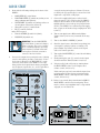
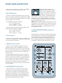
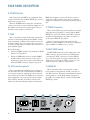
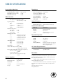
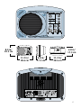
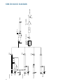
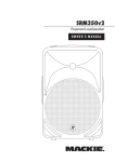
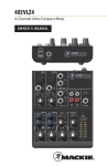
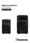
SRM150 Compact Active PA System USer’s manual SRM150 EQ MAIN U HIGH 12kHz OFF LEVEL -15 MAX +15 U PHANTOM POWER MID 2.5kHz 48V -15 +15 U INSTRUMENT (CH 1) LOW 100Hz -15 1 MIN 2 MAX MIC/LINE MIN +15 3 MAX MIN MAX MIC/LINE L R IMPORTANT SAFETY INSTRUCTIONS 1. Read these instructions. 13.Unplug this apparatus during lightning storms or when unused for long periods of time. 2. Keep these instructions. 14.Refer all servicing to qualified service personnel. Servicing is required when the apparatus has been damaged in any way, such as powersupply cord or plug is damaged, liquid has been spilled or objects have fallen into the apparatus, the apparatus has been exposed to rain or moisture, does not operate normally, or has been dropped. 3. Heed all warnings. 4. Follow all instructions. 5. Do not use this apparatus near water. 6. Clean only with dry cloth. 7. Do not block any ventilation openings. Install in accordance with the manufacturer’s instructions. 8. Do not install near any heat sources such as radiators, heat registers, stoves, or other apparatus (including amplifiers) that produce heat. 9. Do not defeat the safety purpose of the polarized or grounding-type plug. A polarized plug has two blades with one wider than the other. A grounding-type plug has two blades and a third grounding prong. The wide blade or the third prong are provided for your safety. If the provided plug does not fit into your outlet, consult an electrician for replacement of the obsolete outlet. 10.Protect the power cord from being walked on or pinched particularly at plugs, convenience receptacles, and the point where they exit from the apparatus. 11.Only use attachments/accessories specified by the manufacturer. 12.Use only with a cart, stand, tripod, bracket, or table specified by the manufacturer, or sold with the apparatus. When a cart is used, use caution when moving the cart/apparatus combination to avoid injury from tip-over. PORTABLE CART WARNING Carts and stands - The Component should be used only with a cart or stand that is recommended by the manufacturer. A Component and cart combination should be moved with care. Quick stops, excessive force, and uneven surfaces may cause the Component and cart combination to overturn. CAUTION AVIS RISK OF ELECTRIC SHOCK DO NOT OPEN RISQUE DE CHOC ELECTRIQUE NE PAS OUVRIR CAUTION: TO REDUCE THE RISK OF ELECTRIC SHOCK DO NOT REMOVE COVER (OR BACK) NO USER-SERVICEABLE PARTS INSIDE REFER SERVICING TO QUALIFIED PERSONNEL ATTENTION: POUR EVITER LES RISQUES DE CHOC ELECTRIQUE, NE PAS ENLEVER LE COUVERCLE. AUCUN ENTRETIEN DE PIECES INTERIEURES PAR L'USAGER. CONFIER L'ENTRETIEN AU PERSONNEL QUALIFIE. AVIS: POUR EVITER LES RISQUES D'INCENDIE OU D'ELECTROCUTION, N'EXPOSEZ PAS CET ARTICLE A LA PLUIE OU A L'HUMIDITE The lightning flash with arrowhead symbol within an equilateral triangle is intended to alert the user to the presence of uninsulated "dangerous voltage" within the product's enclosure that may be of sufficient magnitude to constitute a risk of electric shock to persons. Le symbole éclair avec point de flèche à l'intérieur d'un triangle équilatéral est utilisé pour alerter l'utilisateur de la présence à l'intérieur du coffret de "voltage dangereux" non isolé d'ampleur suffisante pour constituer un risque d'éléctrocution. The exclamation point within an equilateral triangle is intended to alert the user of the presence of important operating and maintenance (servicing) instructions in the literature accompanying the appliance. Le point d'exclamation à l'intérieur d'un triangle équilatéral est employé pour alerter les utilisateurs de la présence d'instructions importantes pour le fonctionnement et l'entretien (service) dans le livret d'instruction accompagnant l'appareil. 15.This apparatus shall not be exposed to dripping or splashing, and no object filled with liquids, such as vases, shall be placed on the apparatus. 16.This apparatus has been designed with Class-I construction and must be connected to a mains socket outlet with a protective earthing connection (the third grounding prong). 17.This apparatus has been equipped with an all-pole, rocker-style AC mains power switch. This switch is located on the rear panel and should remain readily accessible to the user. 18.This apparatus does not exceed the Class A/Class B (whichever is applicable) limits for radio noise emissions from digital apparatus as set out in the radio interference regulations of the Canadian Department of Communications. ATTENTION — Le présent appareil numérique n’émet pas de bruits radioélectriques dépassant las limites applicables aux appareils numériques de class A/de class B (selon le cas) prescrites dans le réglement sur le brouillage radioélectrique édicté par les ministere des communications du Canada. 19.Exposure to extremely high noise levels may cause permanent hearing loss. Individuals vary considerably in susceptibility to noise-induced hearing loss, but nearly everyone will lose some hearing if exposed to sufficiently intense noise for a period of time. The U.S. Government’s Occupational Safety and Health Administration (OSHA) has specified the permissible noise level exposures shown in the following chart. According to OSHA, any exposure in excess of these permissible limits could result in some hearing loss. To ensure against potentially dangerous exposure to high sound pressure levels, it is recommended that all persons exposed to equipment capable of producing high sound pressure levels use hearing protectors while the equipment is in operation. Ear plugs or protectors in the ear canals or over the ears must be worn when operating the equipment in order to prevent permanent hearing loss if exposure is in excess of the limits set forth here. Duration Per Day In Hours Sound Level dBA, Slow Response Typical Example 8 90 6 92 Duo in small club 4 95 Subway Train 3 97 2 100 1.5 102 1 105 0.5 110 0.25 or less 115 Very loud classical music Tami screaming at Adrian about deadlines Loudest parts at a rock concert WARNING — To reduce the risk of fire or electric shock, do not expose this apparatus to rain or moisture. Contents IMPORTANT SAFETY INSTRUCTIONS...................................................................................................2 INTRODUCTION......................................................................................................................................... 4 QUICK START................................................................................................................................................5 HOOKUP DIAGRAMS................................................................................................................................ 6 FRONT PANEL DESCRIPTION.................................................................................................................. 8 1. MIC/LINE Inputs..............................................................................................................................................................8 2. Stereo Input......................................................................................................................................................................8 3. Channel Gain Controls...................................................................................................................................................8 4. INSTRUMENT Switch (CH 1).........................................................................................................................................8 5. 48V PHANTOM POWER Switch and Indicator........................................................................................................8 6. MAIN LEVEL......................................................................................................................................................................9 7. HIGH, MID, and LOW EQ................................................................................................................................................ 9 REAR PANEL DESCRIPTION....................................................................................................................10 8. POWER Switch................................................................................................................................................................10 9. FUSE....................................................................................................................................................................................10 10. AC Power Receptacle..................................................................................................................................................10 11. THRU Connector............................................................................................................................................................10 12. MIC/LINE Switch..........................................................................................................................................................10 13. MAIN IN...........................................................................................................................................................................10 PLACEMENT.................................................................................................................................................11 THERMAL CONSIDERATIONS.................................................................................................................11 AC POWER CONSIDERATIONS..............................................................................................................12 CARE AND MAINTENANCE.....................................................................................................................12 CONNECTIONS.......................................................................................................................................... 13 SERVICE INFORMATION..........................................................................................................................14 Warranty Service................................................................................................................................................................14 Troubleshooting.................................................................................................................................................................14 Repair.....................................................................................................................................................................................15 SRM150 SPECIFICATIONS........................................................................................................................16 SRM150 BLOCK DIAGRAM......................................................................................................................18 SRM150 LIMITED WARRANTY...............................................................................................................19 Don’t forget to visit our website at www.mackie.com for more information about this and other Mackie products. Part No. 0019782 Rev. A 12/06 ©2006 LOUD Technologies Inc. All Rights Reserved. Printed in China. INTRODUCTION The Cabinet Thank you for choosing a Mackie compact active PA system for your sound reinforcement applications. The SRM150 cabinet was designed with the same material as our SRM350 and SRM450 loudspeakers, the strongest molded composite cabinet on the planet. It has an insert in the bottom for mic stand mounting (using the mic stand adapter included with your SRM150), and a threaded insert in the top for mounting a microphone boom (using the included boom extender). The SRM150 is an active PA system that provides a built-in mixer, high sound pressure levels, and is designed to give you the best performance of any compact PA system in its class and price range. Our design goal was to build a compact PA system with: 1. High precision, high output, and accurate playback. 2. Controlled, smooth dispersion of mid and high frequencies. 3. Ultra-clean, high-headroom mic preamps. 4. High-output Class-D amplification. 5. Onboard Mackie mixer with 3-band EQ. Through the combined resources of our top-notch mechanical and analog engineers, we were able to achieve our design goals in every aspect. The result is a sound reinforcement PA system equally at home in a concert setting, in the studio, or impromptu concerts on the studio roof. The Transducer The SRM150 active loudspeaker features a full-range 5.25-inch neodymium driver. Power Amplifier Each SRM150 includes a Class-D power amplifier capable of producing 150 watts peak before clipping. The amplifier includes the following features: • The amplifier produces up to 100 watts rms continuous before clipping (150 watts peak). • A built-in limiter acts when the input signal is large enough to cause clipping, distortion, and excessive voice coil heat. The limiter will automatically decrease the signal going to the amplifier to a safe level. Warning: Although the amplifier has a limiter protection circuit, you must still make sure you don’t overdrive the amplifier. If you hear any distortion, turn down the input (MIC/LINE) gain control, or turn down the MAIN LEVEL control. Its light weight and durable finish make it ideal for portable sound system use. In addition, the unique design of the cabinet makes it easy to use as a floor wedge for stage monitor applications. The Active Advantage There are a number of advantages to using an active speaker system over a passive loudspeaker: • The amplifiers are designed specifically for the speaker load impedance. There is no guesswork as to what load the amplifier has to drive, so it can provide maximum acoustic output from the speaker, yet minimize the danger of speaker damage due to overdriving a lesser amplifier. • The connecting wires between the amplifier output and the driver is kept to a minimum, so the damping factor of the amplifier isn’t compromised by the resistance of long speaker cables. In addition, all the power from the amplifier is transferred directly to the driver with no speaker cable losses. • The presence of active circuits within the speaker cabinet allow the designer to add on extra details, such as a high quality mic/line input section. In short, all the complex interconnected components in the system are designed to work in harmony with each other to produce the best possible sound. QUICK START 1. Start with the following settings on the front of the SRM150: connections from microphones. Channel 3 has stereo RCA jacks [2] specifically for a stereo line-level input from a tape deck or CD player. • MAIN LEVEL [6] control down. • PHANTOM POWER [5] switch out (unless you are 3. Connect the supplied AC power cord to the AC power receptacle [10] on the back of the SRM150. using condenser microphones). Plug the other end into an AC outlet properly con• INSTRUMENT [4] switch out (unless you have an figured with the correct voltage for your particular electric guitar connected to channel 1). model. (The SRM150 has a universal power supply • Channels 1-3 gain [3] controls down. that accepts an AC mains voltage ranging from 100V • EQ [7] controls centered. to 240 V.) And on the rear panel: 4. Turn on your signal source. Make sure its Master • Turn the POWER [8] switch off (down). Volume control (if it has one) is turned all the way • MIC/LINE [12] switch out. down. WARNING: Turn the MAIN LEVEL [6]control down (counterclockwise) before every use. If not, you could be in for a startling surprise, especially if the last time you used it was with a microphone and now you want to connect a line-level source. 2. Connect the output from your signal source (mixing console, microphone, preamp, or other mic- or linelevel source) directly to the MIC/LINE [1] combo connector on the front of the SRM150. It accepts balanced line-level signals from mixers, preamplifiers, CD players, tape decks, etc., and accepts direct 5. Turn on the SRM150 POWER [8] switch. 6. Start the signal source, whether it be speaking into a microphone, playing a guitar, or starting a CD player. Adjust any volume controls on the signal source for normal operation. 7. Turn up the MAIN LEVEL [6] control about halfway (12 o’clock). 8. Slowly turn up the gain [3] controls for the input channels until the desired volume is reached. 9. If it gets really loud, really fast, try turning down the MAIN LEVEL control (or the input source volume control, if it has one). If it doesn’t get very loud, even with the input channel gain control all the way up, try turning up the MAIN LEVEL control (or the input source volume control, if it has one). SRM150 EQ MAIN U HIGH 10. If there is no sound, always turn down the SRM150 MAIN LEVEL control before investigating. There may be a mixer or preamplifier mute or tape switch engaged, or a mic switch off. 12kHz OFF LEVEL -15 MAX +15 U PHANTOM POWER MID 2.5kHz 48V -15 +15 U INSTRUMENT (CH 1) LOW 100Hz -15 1 MIN 2 MAX MIC/LINE MIN +15 3 MAX MIN MAX MIC/LINE L 100V - 240V ~ 50/60Hz 45VA THRU POWER FUSE LINE MIC 3 A M P R C US SRM150 HOOKUP DIAGRAMS Vocal Mic Boom Extender (Included) MP3 Player SRM150 MAIN EQ U HIGH Electric Guitar 12kHz OFF LEVEL -15 MAX +15 U PHANTOM POWER MID 2.5kHz 48V -15 +15 U INSTRUMENT (CH 1) LOW 100Hz -15 1 MIN 2 MAX MIC/LINE MIN +15 3 MAX MIN MAX MIC/LINE L R This illustrates how to use the SRM150 as a personal monitor. Mount the SRM150 on a microphone stand using the Mic Stand Mounting Bracket included with the SRM150. Attach the Boom Extender (also included) to the top of the SRM150 and use a microphone boom to hold your microphone. Mic Stand Adapter (Included) Power Cord Connect the microphone and an instrument to the SRM150 (Channels 1 and 2), and a playback device like an MP3 player to Channel 3. SRM150: PRACTICE SETUP USING MIC STAND AND BOOM Vocal Mic SRM450 Boom Extender (Included) SRM150 MAIN EQ U HIGH Electric Guitar 12kHz OFF LEVEL -15 MAX +15 U PHANTOM POWER MID 2.5kHz 48V -15 +15 U INSTRUMENT (CH 1) LOW 100Hz -15 1 MIN 2 MAX MIC/LINE MIN +15 3 MAX MIN MAX MIC/LINE L THRU Out R Mic Stand Adapter (Included) To Input Power Cord Power Cord Here the SRM150 is used as a personal monitor and the SRM450 is the main PA speaker. SRM150: SMALL CLUB SETUP WITH SRM450 Stereo line-level output Keyboard or other line-level instrument SRM150 MAIN SRM150 EQ MAIN EQ U U HIGH HIGH 12kHz OFF LEVEL 12kHz -15 MAX +15 OFF U PHANTOM POWER LEVEL -15 MAX -15 MID 2.5kHz 48V +15 U -15 LOW 100Hz 100Hz -15 1 MIN 2 MAX MIC/LINE MIN +15 -15 1 3 MAX +15 U INSTRUMENT (CH 1) LOW +15 U PHANTOM POWER MID 2.5kHz 48V INSTRUMENT (CH 1) MIN MAX MIN 2 MAX MIC/LINE MIC/LINE MIN +15 3 MAX MIN MAX MIC/LINE L L R R MAIN IN MAIN IN Stereo Monitor Out Power Cord Vocal Mics Power Cord Electric Guitar 1 ON 2 YX MIC PRE YX ON 3 MIC PR E ON BAL/UNBAL 4 YX MIC PRE ON BAL/UNBAL L 2 LEFT (MONO) AUX SEND Two SRM150s are used as floor monitors to provide a stereo monitor mix for the keyboard player. HI-Z 2 MIC HI-Z LINE 3 LINE 4 BAL/ UNBAL BAL/ UNBAL MIC HI-Z 75Hz 18dB/OCT 48V 20 40 20 48V 30 U 40 20 40 2 LEFT RIGHT (MONO) LINE IN 9-10 (MONO) RIGHT LEFT 20 30 U L OUT L L L L BAL/ UNBAL BAL/ UNBAL BAL/ UNBAL R R R R U R TAPE PHONES (MONO) BAL/ UNBAL U R RIGHT MAIN OUT LINE IN 11-12 (MONO) PREMIUM ANALOG MIXER w/ PERKINS EQ & FIREWIRE OPTION CONTROL ROOM/ PHONES SOURCE 48V 30 U 1 AUX RETURN LINE IN 7-8 (MONO) 75Hz 18dB/OCT 48V 30 U BAL/UNBAL IN 1 LINE IN 5-6 HI-Z 1 BAL/UNBAL YX MIC PRE U LEFT RIGHT 0dB=0dBu U 20 CLIP 40 10 U -20dB 60 U -20dB +40dB GAIN 60 -20dB +15 U -15 +15 -15 +15 U -15 +15 OO MAX -15 +15 U -15 +15 OO MAX 2 U ALT 3-4 HIGH MAX +15 U -15 +15 OO MAX +15 7 +15 +15 OO MAX OO MAX 2 PAN +15 MAX OO MAX 2 PAN LOW 80Hz -15 +15 AUX AUX 1 OO MAX OO MAX 2 PAN RUDE SOLO U 80Hz +15 1 OO ASSIGN TO MAIN MIX +15 LOW -15 AUX 1 MAX 30 MID 2.5kHz -15 U 80Hz -15 AUX OO +15 LOW 80Hz -15 1 20 MID 2.5kHz -15 U LOW 80Hz MAX +15 10 U MID 2.5kHz -15 U LOW AUX OO 2 PAN -15 1 OO MAX OO MAX 2 PAN 2 PAN MAX OO OO CONTROL ROOM L R MUTE MUTE ALT 3/4 dB 10 5 10 20 Two SRM150s: STEREO MONITORING dB 10 +10 0 -20 U 5 10 20 dB 10 +10 0 -20 U 5 10 20 dB 10 +10 0 -20 U 5 10 20 dB 10 +10 0 -20 U 5 10 20 dB 10 +15 PRE POST OO +15 2 +10 0 -20 U 5 10 20 dB 10 +10 0 -20 U 5 10 20 dB 10 +10 0 -20 U 5 10 20 30 30 30 30 30 30 30 40 50 60 40 50 60 40 50 60 40 50 60 40 50 60 40 50 60 40 50 60 40 50 60 OO OO OO OO OO OO OO OO SOLO SOLO SOLO SOLO SOLO SOLO TALKBACK 11 12 OO +10 OO +10 2 POWER MAIN MIX dB 10 OO 5 OL 30 SOLO MIC ALT 3/4 9 10 5 OL 1 FX TO MON PAN MUTE ALT 3/4 7 8 5 OL AUX RETURN 1 OO L R MUTE ALT 3/4 5 6 5 OL L R MUTE ALT 3/4 4 5 OL L R MUTE ALT 3/4 3 5 OL L R MUTE ALT 3/4 2 5 OL L R MUTE ALT 3/4 1 5 U L R MAX PHONES AUX MASTER PRE POST TALK BACK L R LEVEL SET 4 12kHz -15 U MID 1 OO 2 PAN -15 80Hz AUX 1 MAX U 2.5kHz MID LOW 80Hz OO +15 TAPE FREQ 8k U AUX 1 0 2 12kHz -15 2 (OPTION) 1k 100 MID LOW 80Hz +15 4 HIGH 12kHz -15 7 FIREWIRE EQ OUT IN U HIGH 12kHz +15 MAIN MIX +20dB GAIN EQ OUT IN U HIGH -15 -20dB +20dB GAIN EQ OUT IN U 12kHz +15 -20dB +20dB GAIN EQ OUT IN U FREQ 8k U LOW MAX -20dB +20dB GAIN HIGH -15 +15 1k 100 MID AUX OO -20dB EQ OUT IN 12kHz -15 FREQ 8k U MID 60 +40dB GAIN HIGH 12kHz +15 1k 100 U -15 -20dB U HIGH -15 FREQ 8k U EQ OUT IN U 12kHz +15 1k 100 60 +40dB GAIN EQ OUT IN U HIGH -15 U +40dB GAIN EQ OUT IN U MAX 5 LEVEL U OL 5 +10 0 -20 10 EXTERNAL MIC 20 DESTINATION 30 PHONES AUX 1-2 40 50 60 OO SOLO TALKBACK SRM150 MAIN EQ U HIGH 12kHz OFF LEVEL -15 MAX +15 U PHANTOM POWER MID 2.5kHz 48V -15 +15 U INSTRUMENT (CH 1) LOW 100Hz -15 1 MIN 2 MAX MIC/LINE MIN Audio +15 3 MAX MIN TV Monitor MAX MIC/LINE L R Mic Stand Adapter (Included) Power Cord DVD Player SRM150: A/V Cart FRONT PANEL DESCRIPTION Most of the connections and controls on the SRM150 are located on the front panel for easy access. 1. MIC/LINE Inputs Channels 1 and 2 have Neutrik® combo connectors, which accept balanced microphone inputs from an XLR connector, or balanced and unbalanced line-level inputs from a 1/4" TRS or TS connector. The XLR inputs are wired as follows: Pin 1 = Shield or ground Pin 2 = Positive (+ or hot) Pin 3 = Negative (– or cold) The 1/4" inputs are wired as follows and will accept both balanced and unbalanced inputs: Sleeve = Shield or ground Tip = Positive (+ or hot) Ring = Negative (– or cold) 2. Stereo Input Channel 3 has a pair of RCA connectors, which accept a stereo line-level input from a CD player or MP3 player (or any other line-level device). Plugging a guitar straight into a typical line-level input can result in the loss of gain, especially at high frequencies, resulting in a dull sound. Normally, you must use a direct box between a guitar and a mixer’s or preamplifier’s input, which serves to convert the impedance of the guitar from high to low. The Instrument input on channel 1 makes the need for a direct box unnecessary. It’s like it has its own built-in direct box! However: The Instrument input is unbalanced, so if you are running a long cord between the instrument and the SRM150 (say over 20 feet), it is best to use a direct box with a balanced output to avoid picking up noise over the length of the cord. 5. 48V PHANTOM POWER Switch and Indicator Most professional condenser microphones require phantom power, which is a low-current DC voltage delivered to the microphone on pins 2 and 3 of the XLR microphone connector. Push in the 48V button if your microphone requires phantom power. An LED lights next to the button to indicate that phantom power is active. 3. Channel Gain Controls These are used to adjust the signal level for each individual channel. Since the SRM150 incorporates Mackie’s world-class low-noise mic preamp technology, you can connect either a line-level or a microphone-level signal to the input, and use this control to adjust the level correctly. Follow the Quick Start guide on page 4 for setting the gain controls. For most applications, it will be in the 12 o’clock position. If you have a particularly high line-level signal connected to the SRM150, you may need to turn the control down to the 9 o’clock position. If you have a low line-level or mic-level signal connected, you may need to turn the gain control up to the 3 o’clock position. 4. INSTRUMENT Switch (CH 1) Push in this button to change the 1/4" line input on channel 1 to an instrument input. When the button is out, the 1/4" input accepts normal line-level signals from low-impedance sources. When the button is pushed in, the 1/4" input accepts high-impedance signals from instruments with electric pickups, which you would normally run through a DI box. SRM150 EQ MAIN U HIGH 12kHz OFF LEVEL -15 MAX +15 U PHANTOM POWER MID 2.5kHz 48V -15 +15 U INSTRUMENT (CH 1) LOW 100Hz -15 1 MIN 2 MAX MIC/LINE MIN +15 3 MAX MIN MAX MIC/LINE L R This is a global phantom power switch and applies 48V to the XLR input connectors on channels 1 and 2. 7. HIGH, MID, and LOW EQ Dynamic microphones, like Shure’s SM57 and SM58, do not require phantom power. However, phantom power will not harm most dynamic microphones should you accidentally plug one in while the phantom power is turned on. Be careful with older ribbon microphones. Check the manual for your microphone to find out for sure whether or not phantom power can damage it. Use the EQ controls to make overall adjustments to the sound of the SRM150. The HIGH EQ provides a boost or cut of up to 15 dB for the very high frequencies, above 12 kHz. These frequencies include the sizzle of cymbals, the edge of a guitar, or the upper harmonics of vocals. In general, boosting the HIGH EQ will brighten the sound of the loudspeaker. 6. MAIN LEVEL The MID EQ provides a boost or cut of up to 15 dB for the mid-range frequencies around 2.5 kHz. Most vocals are located in the mid-range frequencies, so this can be used to bring the vocals up or down in the mix. This is used to adjust the signal level from the SRM150 mixer, going into the built-in power amplifier. Follow the Quick Start guide on page 4 for setting the MAIN LEVEL control. The LOW EQ provides a boost or cut of up 15 dB for the very lowest frequencies, below 100 Hz. These frequencies are represented by the punch in bass drums, bass guitar, and some really serious male singers. SRM150 EQ MAIN U HIGH 12kHz OFF LEVEL -15 MAX +15 U PHANTOM POWER MID 2.5kHz 48V -15 +15 U INSTRUMENT (CH 1) LOW 100Hz -15 1 MIN 2 MAX MIC/LINE MIN +15 3 MAX MIN MAX MIC/LINE L R REAR PANEL DESCRIPTION 8. POWER Switch Switch up to turn the SRM150 on, and switch down to turn it off. Make sure the MAIN LEVEL [6] control is down before you turn it on. When the POWER switch is turned on, and the linecord is connected to an active AC Mains supply, the cool blue LED on the front of the speaker glows to let you know that you’re ready to rock and roll. 9. FUSE This is a resettable circuit breaker that monitors the amount of current being drawn by the SRM150. Under normal operating conditions, this should never pop. An unusual condition may cause the breaker to pop, such as a mains voltage surge occurring at the same time as a peak amplifier output. To reset the breaker: • Turn the POWER [8] switch off and push the FUSE switch to its UP position. • Turn the POWER switch back on and the SRM150 should resume normal operation. If the circuit breaker pops again, there may be something wrong inside the SRM150. Refer to “Repair” on page 15. Note: If you happen to lose the AC linecord, replacements are readily available at any office or computer supply store. Always use a three-pin plug with a ground pin. 11. THRU Connector This is a male XLR connector that produces the main signal just prior to the EQ [7] controls and the MAIN LEVEL [6] control. The signal at the THRU connector includes the input signals connected to channels 1-3 [1/2] and the MAIN IN [13] signal. Use this connector to patch the signal from the SRM150 to another SRM150 or other active loudspeaker (like an SRM350 or SRM450), or to a mixer. 12. MIC/LINE Switch The MIC/LINE switch affects the output level of the THRU connector. Leave the switch out (LINE) when connecting the THRU connector to another SRM150 or to a line-level input on a mixer. Push the switch in (MIC) when connecting the THRU connector to a microphone input on a mixer or a stage snake. 10. AC Power Receptacle 13. MAIN IN This is a standard 3-prong IEC connector. Connect the detachable linecord (included with your SRM150) to the power receptacle, and plug the other end of the linecord into an AC outlet. The SRM150 has a universal power supply that can accept any AC voltage ranging from 100VAC to 240 VAC. No need for voltage select switches. It will work virtually anywhere in the world. This is a Neutrik combo connector that accepts a balanced line-level signal from an XLR connector or a 1/4" TRS connector. The signal is mixed with the signals from channels 1-3 on the main mix bus, just prior to the THRU [11] output, EQ [7] controls and the MAIN LEVEL [6] control. 100V - 240V ~ 50/60Hz 45VA LINE MIC 3 A M P C 10 US THRU POWER FUSE SRM150 MAIN IN PLACEMENT The SRM150 compact active PA systems are designed to sit on the floor, a tabletop, or to fit on a standard microphone stand. You can place the SRM150 on the floor and angle it back to use it as a floor monitor. The unique shape of the cabinet provides a perfect angle for aiming up toward performers from the front of the stage. You can also use the Mic Stand Adapter (included), which allows you to mount the SRM150 onto a standard microphone stand. MIC STAND ADAPTER Here are some other placement tips: • Avoid placing loudspeakers in the corners of a room. This increases the low-frequency output and can cause the sound to be muddy and indistinct. • Avoid placing loudspeakers against a wall. This, too, increases the low frequency output, though not as much as corner placement. However, if you do need to reinforce the low frequencies, this is a good way to do it. • Avoid placing the active loudspeaker directly on a hollow stage floor. A hollow stage can resonate at certain frequencies, causing peaks and dips in the frequency response of the room. It’s better to place the active loudspeaker on a sturdy table or microphone stand. Insert into the bottom of the SRM150 THERMAL CONSIDERATIONS 5/8” adapter threads onto mic stand In addition, there is a threaded insert on top of the cabinet for mounting the boom extender (included). This allows you to attach a microphone boom on top of the SRM150 for your microphone. BOOM EXTENDER Mount Mic Boom on this end The amplifier inside the SRM150 is convection cooled by a large heatsink. For efficient cooling, it is important to allow at least six inches of free space behind the SRM150. If the ambient temperature in the room is high, it could cause the amplifier to overheat. In this case, you should try aiming a fan at the heatsink to increase the air flow through the fins. In the unlikely event that the amplifier does overheat, a built-in thermal switch will activate, placing the SRM150 amplifier into standby. When the amplifier has cooled down to a safe operating temperature, the thermal switch will reset and the SRM150 will resume normal operation. Thread into the top of the SRM150 5/8” threaded boom extension As with any powered components, protect them from moisture. If you are setting them up outdoors, make sure they are under cover if you expect rain. 11 AC POWER CONSIDERATIONS CARE AND MAINTENANCE Be sure the SRM150 is plugged into an outlet that is able to supply enough current for the amplifier. Your Mackie active loudspeaker will provide many years of reliable service if you follow these guidelines: Under maximum SPL conditions, where musical peaks are just hitting the limiter, the SRM150 model draws 2 amps on average. Under normal conditions, the current draw is below 1 amp. We recommend that a stiff (robust) supply of AC power be used because the amplifier places high current demands on the AC line. The more power that is available on the line, the louder the speaker will play and the more peak output power will be available for cleaner, punchier bass. A suspected problem of “poor bass performance” is often caused by a weak AC supply to the amplifier. If lighting is used in a show, it is preferable to power the lights from a separate AC circuit than the one powering the audio equipment. This will help minimize noise from the lights coupling into the audio (particularly if SCRs, or light-dimmer switches, are used). Wherever possible, connect all of your audio equipment to the same electrical circuit. This will help reduce the possibility of a ground loop problem causing an annoying hum in your speakers. A maximum of five SRM150s can be connected per 15A service (120 VAC). This allows each SRM150 to be safely operated at its maximum level. When turning your system on, turn on the SRM150s last. This will stop any turn-on thumps and bangs from your source equipment being amplified. When turning off your system, turn off the SRM150s first. This will prevent any turn-off thumps and bangs from your source equipment being amplified. When setting up for a show, often you are plugging into an AC power distribution system you know nothing about. You may even be faced with 2wire outlets that are missing the third safety ground pin. It’s a good idea to have a three-wire AC outlet tester in your toolbox so you can check the outlets yourself to make sure they are wired correctly. These testers will tell you if the polarity of the hot and neutral wires is reversed and if the safety ground is disconnected. Don’t use an outlet if it is wired improperly! This is to protect yourself as well as your equipment. Never remove the ground pin on the power cord of the SRM150 or any other component. This is very dangerous. 12 Avoid exposing the loudspeaker to moisture. If it is set up outdoors, be sure it is under cover if you expect rain or you live in Washington. • Avoid exposure to extreme cold (below freezing temperatures). If you must operate the loudspeaker in a cold environment, warm up the voice coil slowly by sending a low-level signal through it for about 15 minutes prior to high-power operation. • Use a slighty damp cloth with a mild soap solution to clean the cabinet. Only do this when the power is turned off. Avoid getting moisture into any of the openings of the cabinet, particularly where the driver is located. CONNECTIONS XLR Connectors 1/4" TS Phone Plugs and Jacks Inputs 1-2 accept 3-pin male XLR connectors on the Neutrik combo inputs. They are wired as follows, according to standards specified by the AES (Audio Engineering Society). “TS” stands for Tip-Sleeve, the two connection points available on a mono 1/4" phone jack or plug. They are used for unbalanced line-level signals and the highimpedance instrument input on Channel 1. 2 SHIELD HOT COLD SHIELD SLEEVE TIP TIP 1 3 SLEEVE TIP 1 SLEEVE COLD 3 HOT 2 SHIELD 1 3 COLD 2 HOT XLR Balanced Wiring: Pin 1 = Shield Pin 2 = Hot (+) Pin 3 = Cold (–) RCA Plugs and Jacks 1/4" TRS Phone Plugs and Jacks The Neutrik combo inputs also accept 1/4" TRS connectors. “TRS” stands for Tip-Ring-Sleeve, the three connection points available on a stereo 1/4" or balanced phone jack or plug. TRS jacks and plugs are used for balanced signals and stereo headphones. Balanced Mono 1/4" TS Unbalanced Wiring: Sleeve = Shield Tip = Hot (+) RING SLEEVE SLEEVE RING TIP RCA-type plugs (also known as phono plugs) and jacks are often used in home stereo and video equipment, and to make S/PDIF connections on consumer digital audio devices. They are unbalanced and electrically equivalent to a 1/4" TS phone plug. SLEEVE TIP SLEEVE TIP RCA Unbalanced Wiring: Sleeve = Shield Tip = Hot (+) TIP RING TIP SLEEVE 1/4" TRS Balanced Mono Wiring: Sleeve = Shield Tip = Hot (+) Ring = Cold (–) Stereo Headphones RING SLEEVE SLEEVE RING TIP TIP RING TIP SLEEVE 1/4" TRS Stereo Unbalanced Wiring: Sleeve = Shield Tip = Left Ring = Right 13 SERVICE INFORMATION Warranty Service Details concerning Warranty Service are spelled out on page 19 of this manual. If you think your loudspeaker has a problem, please check out the following troubleshooting tips and do your best to confirm the problem. Visit the Support section of our website (www.mackie.com/support) where you will find lots of useful information such as FAQs, documentation, and user forums. You may find the answer to the problem without having to send your loudspeaker away. Troubleshooting No power! • Our favorite question: Is it plugged in? Make sure the AC outlet is live (check with a tester or lamp). • Our next favorite question: Is the POWER switch on? If not, try turning it on. • Is the blue light on the front panel illuminated? If not, make sure the AC outlet is live. If so, refer to “No sound” below. • The resettable circuit breaker has popped. Refer to “FUSE” [9] on page 10 for information on the circuit breaker. No sound! • Is the input gain control [3] or the MAIN LEVEL [6] control turned all the way down? Follow the procedures in the “Quick Start” section on page 4 to verify that all the volume controls in the system are properly adjusted. • Is the signal source working (and making union scale)? Make sure the connecting cables are in good repair and securely connected at both ends. Make sure the output volume (gain) control on whatever is connected to the SRM150 is turned up sufficiently to drive the inputs of the speaker. 14 Bad sound! • Is it loud and distorted? Follow the procedures described in the “Quick Start” section to verify that the levels are set properly. • Is the input connector plugged completely into the jack? Be sure all connections are secure. It’s a good idea to periodically clean all electrical connections with a non-lubricating electrical contact cleaner. Noise • Make sure all connections to the active speakers are good. • Make sure none of the signal cables are routed near AC cables, power transformers, or other EMI-inducing devices. • Is there a light dimmer or other SCR-based device on the same AC circuit as the SRM150? Use an AC line filter or plug the SRM150 into a different AC circuit. Hum • Turn the MAIN LEVEL control all the way down. If the noise disappears, it’s coming from the signal source. If not, try disconnecting the cables connected to the input jacks one at a time. If the noise disappears, it could be a “ground loop,” rather than a problem with the SRM150. Try some of the following troubleshooting ideas: • Use balanced connections throughout your system for the best noise rejection. • Whenever possible, plug all the audio equipment’s linecords into outlets which share a common ground. The distance between the outlets and the common ground should be as short as possible. Never remove the ground pin on the power cord of the SRM150 or any other component. This is very dangerous. Repair Service for Mackie products is available at a factoryauthorized service center. Service for Mackie products living outside the United States can be obtained through local dealers or distributors. If your SRM150 needs service, follow these instructions: 1. Review the preceding troubleshooting suggestions. Please. 2. Call Tech Support at 1-800-898-3211, 7 am to 5 pm PST, to explain the problem and obtain a Service Request Number. Have your SRM150’s serial number ready. You must have a Service Request Number before you can obtain factory-authorized service. 8. You will need to contact the authorized service center for their latest turn-around times when you call for your Service Request Number. The SRM150 must be packaged in its original packing box, and must have the Service Request Number on the box. Once it’s repaired, the authorized service center will ship it back prepaid (if it was a warranty repair). Note: Under the terms of the warranty, you must ship or drop-off the unit to an authorized service center. The return ground shipment is covered for those units deemed by us to be under warranty. Note: You must have a sales receipt from an Authorized Mackie Dealer to qualify for a warranty repair. 3. Keep this owner’s manual and the detachable linecord. We don’t need them to repair the SRM150. 4. Pack the SRM150 in its original package, including endcaps and box. This is VERY IMPORTANT. When you call for the Service Request Number, please let Tech Support know if you need new packaging. Mackie is not responsible for any damage that occurs due to non-factory packaging. 5. Include a legible note stating your name, shipping address (no P.O. boxes), daytime phone number, Service Request Number, and a detailed description of the problem, including how we can duplicate it. 6. Write the Service Request Number in BIG PRINT on top of the box. Units sent without the Service Request Number will be refused. 7. Tech Support will tell you where to ship the SRM150 for repair. We suggest insurance for all forms of cartage. Need Help? • Visit www.mackie.com and click Support to find: FAQs (Frequently Asked Questions), manuals, addendums, and user forums. • Email us at: [email protected]. • Telephone 1-800-898-3211 to speak with one of our splendid technical support representatives (Monday through Friday, from 7 AM to 5 PM PST). R 15 SRM150 SPECIFICATIONS System Specifications Transducer Frequency Response (–3 dB) 100 Hz – 17.5 kHz Diameter Frequency Range (–10 dB) 60 Hz – 22 kHz Voice Coil Diameter 1.0 in/25.4 mm Max SPL Long-term @ 1m 110 dB Sensitivity (1W@1m)90 dB Max SPL Peak @ 1m 120 dB Nominal Impedance 8 ohms Power Handling 150 watts Frequency Range 90 Hz – 20 kHz Magnet Type Neodymium Mixer Section Frequency Response (–3 dB) Mic Input to Line Out (Gain at 0 dB) 5 Hz – 40 kHz (+0, –1 dB) Input Impedance Mic3 kohm balanced Hi-Z20 kohm balanced Instrument 1 Mohm Line 10 kohm balanced Stereo 10 kohm balanced Maximum Voltage Gain Mic Input 1 51 dB Mic Input 2 51 dB Stereo Input 9 dB Maximum Input Level Mic Line Stereo –28 dBu, gain at +50 dB +15 dBu, gain at +6 dB –8 dBu, gain at +30 dB +35 dBu, gain at –15 dB +20 dBu, gain at 0 dB 3-Band Equalization High Mid Low ±15 dB @ 12 kHz ±15 dB @ 2.5 kHz ±15 dB @ 100 Hz –30 dB Line Out Pad 5.25 in/134 mm Safety Features Overload Protection Limiter Thermal Protection Amplifier shutdown, auto-reset Construction Features Material Polypropylene Finish Grey textured finish Handle Grille Top mounted Perforated metal with weather- resistant coating Physical Properties Height 8.0 in/20.3 cm Width 11.2 in/28.4 cm Depth 6.8 in/17.3 cm Weight 7.6 lb/3.4 kg Mounting Methods Mic stand mountable via the built-in socket on the bottom of the cabinet with the supplied adapter. Common Mode Rejection Ratio (CMRR) 55 dB @ 1 kHz, gain at unity AC Power Requirements 100 VAC – 240 VAC, 50/60 Hz, 35 VA Noise (20 Hz to 20 kHz BW, 150 ohm source impedance) Equivalent Input Noise (EIN) –129 dBu Residual Output Noise (Line out, channel and master levels off) –85 dBu AC Connector3-pin IEC 250 VAC Power Amplifier Rated Power 100 watts rms continuous, 20 Hz to 20 kHz Maximum Power 150 watts peak Rated THD 0.05% Cooling Convection Extrusion Design Class D Disclaimer Since we are always striving to make our products better by incorporating new and improved materials, components, and manufacturing methods, we reserve the right to change these specifications at any time without notice. “Mackie.” and the “Running Man” figure are registered trademarks of LOUD Technologies Inc. All other brand names mentioned are trademarks or registered trademarks of their respective holders, and are hereby acknowledged. ©2006 LOUD Technologies Inc. All Rights Reserved. R 16 SRM150 EQ MAIN U HIGH 12kHz OFF LEVEL -15 MAX +15 U PHANTOM POWER MID 2.5kHz 48V -15 +15 U INSTRUMENT (CH 1) LOW 100Hz -15 1 MIN 2 MAX MIC/LINE MIN +15 3 MAX MIN MAX MIC/LINE L R SRM150 MAIN EQ U 8.0 in/ 20.3 cm HIGH 6.8 in/ 17.3 cm 12kHz OFF LEVEL -15 MAX +15 U PHANTOM POWER MID 2.5kHz 48V -15 +15 U INSTRUMENT (CH 1) LOW 100Hz -15 1 MIN 2 MAX MIN MIC/LINE +15 3 MAX MIN MAX MIC/LINE L R 6.8 in/ 17.3 cm 11.2 in/ 28.4 cm 100V - 240V ~ 50/60Hz 45VA THRU POWER FUSE 11.2 in/ 28.4 cm MAIN IN LINE MIC 7 A M P C US SRM150 17 18 1 3 2 Main In Channel 3 Line Mic Channel 2 1 1 3 2 3 2 Phantom 48V Line Mic Channel 1 Hi-Z Line Instrument - + Gain - + Gain - + Gain HI 12K MID 100 2.5K LO 3-Band EQ - + Main Level Limiter Line Mic (–30 dB) 1 THRU Power Amplifier 3 2 Loudspeaker SRM150 BLOCK DIAGRAM SRM150 LIMITED WARRANTY Please keep your sales receipt in a safe place. A. LOUD Technologies Inc. warrants all materials, workmanship and proper operation of this product for a period of five years from the original date of purchase, with the following exception: warranty on all loudspeaker components including woofers and compression drivers are only warranted for two years. If any defects are found in the materials or workmanship or if the product fails to function properly during the applicable warranty period, LOUD Technologies, at its option, will repair or replace the product. This warranty applies only to equipment sold and delivered within the U.S. by LOUD Technologies Inc. or its authorized dealers. B. Failure to register online or return the product registration card will not void the one-year warranty. C. Service and repairs of Mackie products are to be performed only at a factory-authorized facility (see D below). Unauthorized service, repairs, or modification will void this warranty. To obtain repairs under warranty, you must have a copy of your sales receipt from the authorized Mackie dealer where you purchased the product. It is necessary to establish purchase date and determine whether your Mackie product is within the warranty period. D. To obtain factory-authorized service: 1. Call Mackie Technical Support at 800/898-3211, 7 AM to 5 PM Monday through Friday (Pacific Time) to get a Service Request Number. Products returned without a Service Request Number will be refused. 2. Pack the product in its original shipping carton. Also include a note explaining exactly how to duplicate the problem, a copy of the sales receipt with price and date showing, and your return street address (no P.O. boxes or route numbers, please!). If we cannot duplicate the problem or establish the starting date of your Limited Warranty, we may, at our option, charge for service time. 3. Ship the product in its original shipping carton, freight prepaid to the authorized service center. The address of your closest authorized service center will be given to you by Technical Support. IMPORTANT: Make sure that the Service Request Number is plainly written on the shipping carton. E. LOUD Technologies reserves the right to inspect any products that may be the subject of any warranty claims before repair or replacement is carried out. LOUD Technologies may, at our option, require proof of the original date of purchase in the form of a dated copy of the original dealer’s invoice or sales receipt. Final determination of warranty coverage lies solely with LOUD Technologies. F. Any products returned to one of the LOUD Technologies factory-authorized service centers and deemed eligible for repair or replacement under the terms of this warranty will be repaired or replaced within thirty days of receipt. LOUD Technologies and its authorized service centers may use refurbished parts for repair or replacement of any product. Products returned to LOUD Technologies that do not meet the terms of this Warranty will be not be repaired unless payment is received for labor, materials, return freight, and insurance. Products repaired under warranty will be returned freight prepaid by LOUD Technologies to any location within the boundaries of the USA. G. LOUD Technologies warrants all repairs performed for 90 days or for the remainder of the warranty period. This warranty does not extend to damage resulting from improper installation, misuse, neglect or abuse, or to exterior appearance. This warranty is recognized only if the inspection seals and serial number on the unit have not been defaced or removed. H. LOUD Technologies assumes no responsibility for the quality or timeliness of repairs performed by an authorized service center. I. This warranty is extended to the original purchaser and to anyone who may subsequently purchase this product within the applicable warranty period. A copy of the original sales receipt is required to obtain warranty repairs. J. This is your sole warranty. LOUD Technologies does not authorize any third party, including any dealer or sales representative, to assume any liability on behalf of LOUD Technologies or to make any warranty for LOUD Technologies Inc. K. THE WARRANTY GIVEN ON THIS PAGE IS THE SOLE WARRANTY GIVEN BY LOUD TECHNOLOGIES INC. AND IS IN LIEU OF ALL OTHER WARRANTIES, EXPRESS AND IMPLIED, INCLUDING THE WARRANTIES OF MERCHANTABILITY AND FITNESS FOR A PARTICULAR PURPOSE. THE WARRANTY GIVEN ON THIS PAGE SHALL BE STRICTLY LIMITED IN DURATION TO FIVE YEARS FROM THE DATE OF ORIGINAL PURCHASE FROM AN AUTHORIZED MACKIE DEALER. UPON EXPIRATION OF THE APPLICABLE WARRANTY PERIOD, LOUD TECHNOLOGIES INC. SHALL HAVE NO FURTHER WARRANTY OBLIGATION OF ANY KIND. LOUD TECHNOLOGIES INC. SHALL NOT BE LIABLE FOR ANY INCIDENTAL, SPECIAL, OR CONSEQUENTIAL DAMAGES THAT MAY RESULT FROM ANY DEFECT IN THE MACKIE PRODUCT OR ANY WARRANTY CLAIM. Some states do not allow exclusion or limitation of incidental, special, or consequential damages or a limitation on how long warranties last, so some of the above limitations and exclusions may not apply to you. This warranty provides specific legal rights and you may have other rights which vary from state to state. 19 16220 Wood-Red Road NE • Woodinville, WA 98072 • USA United States and Canada: 800.898.3211 Europe, Asia, Central and South America: 425.487.4333 Middle East and Africa: 31.20.654.4000 Fax: 425.487.4337 • www.mackie.com E-mail: [email protected]