1
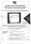
LASER CLEAN HEATING SYSTEMJVENTED HEATER
INSTALLAT10N AND OPERAT10N INSTRUCT10NS
LASER CLEAN VENttED
M'DELLasgr
30
ф
(Type C〕
!MPORTAN丁
READ AND UNDERSTANDINSTRUCT10NS BEFOREINSTALLING OR USING HEATER.
RETAIN INSTRUCT10NS FOR FUTURE REFERENCEoCHECK LOCAL CODES AND ORDINANCES FOR PERMITTED USE。
CONTENTS
SECT10N A:
¨¨¨¨¨¨・
・
・
¨"¨¨"。・
・
・
“¨¨………“¨・
・2
Specifications・
SEC丁 10N B:
・
…………¨…・
。3
Safety Tips for Operation ¨ ¨¨¨¨¨“・
SEC丁 10N C:
・
¨¨・
・
・
“¨¨¨¨・
・
・4
¨¨・
・
""・・
・
・
・
・
・
""・・
・
Fue:Guide ¨ "・・
SEC丁 10N D:
・
……¨¨“¨・5
Operating Controls and Part Names ・
SECT10N E:
Operation
・8
・
¨¨・
Before lgnition "¨ ¨¨¨¨¨¨¨¨¨¨¨…………・
・
¨"・・8
・
¨¨・
・
¨“¨¨¨・
・
¨"・・
“¨・
0peration "¨ ¨"“・
・
¨"¨・
・
¨…………… 11
Turning Heater Off"¨ ¨¨¨¨¨・
SECT10N F:
R o u t i n e r u a i n t e n a n c e“
・¨¨¨" ¨" ¨" ¨¨¨¨¨¨" ¨。1 2
SECT10N G:
Troubleshooting・ ¨¨¨¨¨¨"¨¨“"¨¨…………………。14
SEC丁 10N H:
“・
・
・
・
・
"¨・
・
““・
・15
Long tterrn Storage ¨ ““"¨“¨¨・
SECT10N l:
!nsta‖ation
丁oois Needed forlnsta‖ ation・"¨¨………………… 16
・
““¨¨・
・
¨………¨。16
Standard lnsta‖ ation Parts・ ・
¨
¨
¨
¨
¨
¨
¨
¨
¨
¨
¨
¨
¨
¨
¨¨¨¨・
・18
Accessary Parts・
¨
・
・
¨
・
・
¨
¨
¨
¨
¨
¨
¨
21
Safety Tips for:nsta‖
ation ¨
¨¨……¨・22
1nstaHation of Heater and Flue Pipe・
Perrnanent Wiring lnsta‖
ation ¨ ¨¨¨¨¨¨"… 28
SEC丁 10N J:
・
・
・
・
・
¨¨・
・
¨¨"………・
…¨“・
・
………・
¨¨… 29
Fueling ¨“¨¨・
SECTION A:
SPECIFiCATIONS
M odel:
Laser30
Heater Efficiency:
s 0 %( 1 )
Heat Rat ing:
Hig,h- 14,800BTU/h
Med - 10,000BTU/h
Low - 5,200BTU/h
F uel Cons um p ti o n :
High- 0.108gal/h
Med - 0.076gal/h
Low - 0.040gal/h
Fuel system:
Externaltank (2)
Fuel Type:
ASTM D36991-K Keroseneor ASTM D396No.1 5500
LowSulfurNo.1FuelOil
Dimensions(WxHxD):
16-15116"
x 21-914"x 13-9116"
Weight:
31 lbs.Empty
Vent Pipe Hole:
2-314"- 3" diameter
Maximum Length of Vent Pipe System:
10ft.,3 bendsor less
ElectricalRating:
120VoltsAC,60 Hz
Preheat- 260W
Burning- 26W
Typical Room Size (3):
600squarefeet (0"F)
720squarefeet (20'F)
Heat and vaporized water are produced by the combustion process of this kerosene heater.This rating
does not take into account heat loss due to condensationof water vapor.
2
Externaltank to be purchasedfrom local suppliers.
3
0" F Heat Load = 24 BTUlft'lhr
20" F Heat Load = 20 BTU lft'lhr
Room s i z e fo r w h i c h th i s h e a te r i s s u i tabl ew i l l vary dependi ng on outsi de temperature,house insulation, window size,and other factors.
SECT10N B:
SAFETY ttIPS FOR OPERAT10N
CA UT I O N: H e a te r a n d v e n t p i p e s y s te m must be properl y i nstal l ed before operati on. P l easefollow
i n s tru c ti o n su n d e r " l n s ta l l a ti o n" ,S ecti onl .
1.
Nev er us e a n y fu e l o th e r th a n A ST M D3699 1-K K eroseneor A S TM D 396
N o . 1 5 5 0 0 L o w S u l f u r N o . 1 F u e l O i l . N E V E RU S E G A S O L I N EU
. se of gasoline c an le a d to u n c o n tro l l a b l efl a m e s , resul ti ngi n destructi vefi re.
2.
Due t o hig h s u rfa c ete m p e ra tu re s ,k e e p heateraw ay from chi l dren,furni ture
and c lot hi n g w h i l e i n o p e ra ti o n(Se e P a ge 22l -.
R:GHT
WRONG
T o pr ev en t a b n o rma l o p e ra ti o n a n d p r ol ong heater l i fe, be sure to perform
r out ine m a i n te n a n c e(S e e P a g e s1 2 -1 31.
4.
Nev er s t o re o r tra n s p o rtfu e l i n o th e r th an a metal or pl asti ccontai nerthat i s
( 1 ) a c c e p t a b l ef o r f u e l , ( 2 ) n o n - r e d i n c o l o r , a n d ( 3 ) c l e a r l y m a r k e d ,
" K E R O S E N Eo" r " N O . 1 F U E LO l L " . N e v e rs t o r ef u e l i n t h e l i v i n g s p a c e .
5.
O per at in gT e mp e ra tu reR a n g e
Us e heate r w i th i n th e ra n g e o f te m p e ratures
indic at edi n th e ri g h t fi g u re .
Point B: lf outside temperature -45oF
than room temperature has to be 60"F or above
∽一コO
︵
﹂。︶Φ﹂コ一o﹂ΦaCCO卜 の0一
Point A: lf outside temperature -20"F
than room temperature has to be OoFor above
Room Temperature("F)
SECT10N C:
FUEL GUIDE
The ToyostoveLaser30 is designedfor use with ASTM D36991-K Keroseneor ASTM D396No.1 5500 Low Sulfur
No. 1F uelO il . U s e o f l o w -q u a l i tyfu e l w i l l c a useburnerperformanceto drop, l eadi ngto abnormalcombust ionand
reducedheaterlife.
P ur c has eonl y AS T M D 3 6 9 91 -K K e ro s e n eor A S TM D 396 N o.1 5500 Low S ul fur N o.1 Fuel Oi l i n non-r edcans
reservedexclusivelyfor fuel and marked accordinglywith the word "KEROSENE"or "NO. 1 FUELOlL". Always
store your fuel in a separateareafrom where you store gasolinefor your power equipmentto avoid accidentaluse
of gas olinein y o u r h e a te r.
What to Buy . . .
A LW A Y S : C l e a n a n d h i g h -q u a l i ty A S TM D 3699 1-K K erosene or A S TM
D 3 9 6 N o . 1 5 5 0 0 L o w S u fur N o.1 Fuel Oi l .
ALWAYS :
Fuel free of contaminants,water or cloudiness.
NE V E R:
G a s o l i n e ,a l c o h o l ,w h i te gas, camp stove fuel or addi ti ves.
NE V E R:
Ye l l o w o r s o u r-s me l l i n gfuel .
How to Store lt . . .
A LW A Y S : S to re i n a c l e a n c o n ta i ner, non-red i n col or, cl earl y marked
KEROSENE
o r N O . 1 F U E LO l L .
ALWAYS :
Store away from direct sunlight, heat sources or extreme temperature changes.
NE V E R:
In a g l a s s c o n ta i n e r,o r o ne that has been used for other fuel s.
NE V E R:
F o r l o n g e r th a n s i x mo nths. B egi n each heati ng season w i th
fresh fuel; discard at the end of season.
NE V E R:
In th e l i v i n g s p a c e .
W hy lt is lm p o rta n t. . .
P ur e, c le a n fu e l i s e s s e n ti a l fo r s a fe and effi ci ent heater operati on. P oor
qualit y o r c o n ta mi n a te dfu e l c a n c a u se:
o E x c e s sta r d e p o s i tso n burner and fl ue pi pe
o In c o m p l e tec o m b u s ti o n
o Reducedheater life
Us e of a h i g h l y v o l a ti l efl a mma b l e fu e l such as gasol i necan produce uncontrollable flames, creating a severefire hazard.
SECT10N D:
OPERATING CONTROLS AND PART NAMES
Before using heater,familiarizeyourself with the following operating controls and names.
ER
嘔
□
裏
11は
SAVR
ず
6. Power saver lamp
8.lst T:MERlamp
7.2nd TIMER lamp
1 . O N / O F Fs w i t c h :
Main switch turns heater on and off. When switched on, heater
begins operation and combustion starts after preheatperiod.
2.
Power Saver button:
The button turns Power Saver operation mode on and off.
3.
Timer button:
The button turns Timer operationmode on and off.
4.
set:
Temp./Timer/Clock
Temp./Timer/Clockset modes can be set by pressing UP/HOURor
DOWN/MINbuttons.
5.
Power lamp:
- Heateris in operation.
Lit
F l a s h i n g - P r e - h e a t i n ag n d p r e - p u r g i n g .
6.
PowerSaver lamp
Heateroperatingin PowerSaver mode.
7.
2nd Timer lamp:
Heateroperatingin 2nd Timer settingmode.
8.
1stTimer lamp:
Heateroperatingin 1stTimer settingmode.
9.
Digitalindicator:
Displaysclock,sbt temperature,room temperatureand error code.
10. Temperaturelamp:
- DigitalIndicatorshows set and room temperature.
Lit
Flashing - Set temperaturecan be changed.
11. AM lamp / PM lamp
- Digitallndicatorshows currenttime.
Lit
Flashing - Current ime can be changed.
12. Circulationfan:
Three speed motor supplieshigh-capacitywarm air flow during high
combustionfor heating room up quickly,and low or medium-capacity warm air flow during low or medium combustionfor maintaining
comfortable room temperature.
1 3 . R o o m t e m p e r a t u r es e n s o r C
: o n s t a n t l ys e n s e s r o o m t e m p e r a t u r ea n d s u p p l i e s i n f o r m a t i o n t o
heaterso that desiredroom temperaturecan be maintained.
14. Powersupply cord:
For use in 120V,AC electricaloutlet.
15. Plumb bob:
Allows user to checkif heateris level.
η
│
REF#
PART#
PART NAME
REF#
PART#
PART NAME
8
2
2
9
2
3
。
3
4
︲
3
5
2
3
6
3
3
7
4
3
8
5
3
9
6
3
0
1
7
3
︲
︲
8
3
2
︲
9
3
3
︲
0
4
4
︲
︲
4
5
︲
2
4
6
︲
3
4
7
︲
4
4
8
︲
5
4
9
︲
6
4
0
2
7
4
︲
2
8
4
2
2
9
4
3
2
0
5
4
2
︲
5
5
2
2
5
6
2
Front panel assembly
Top plate assembly
Indicator lamp circuit
Right side panel
Left side panel
Rear guard right
Rear guard left
Rear guard top
Plumb bob
Circulation air filter
Rear panel
Drip tray
Adjustable leg
Leveler fuel pipe
Fusible link valve
Joint gasket
Heat chamber cover
Upper gasket
Heat chamber assembly
Heat element
Lower gasket
Heat chamber gasket
Burnerring
Burner assembly
Burner gasket
Primarv flame rod
20479573
20479612
20474083
20475834
20479518
17185580
20474920
20475831
20475881
20479544
20479591
20479530
20479531
20479637
20479683
20479669
20479671
20478317
20478306
20478534
20479519
20479541
20475535
20478373
20479891
20479521
Burner thermistor
Main circuit board
Fuel nozzle gasket
Fuel nozzle
lgniter
lgniter gasket
lgniter cover
Mica window
Peep window gasket
Heat exchanger
Relief gasket
Pressure relief plate
Relief spring
Blower motor assembly
Air intake fan
Circulation fan motor
Circulation fan
Transformer
High limit switch
Fuelsump
Fuelpump
Fuel pipe assembly
Power supply cord
Thermistor
Standard flue pipe
loniter ouide oasket
REF#
3 4 5 6 7 8 9 0 ︲ 2 3 4 5 6 7
9 。 ︲ 2 3 4 5 6
5 5 5 5 5 5 5 6 6 6 6 6 6 6 6 “ 6 7 7 7 7 7 7 7
7
2
1
20479546
20479660
20479676
20479563
20479564
20479551
20479553
20479550
20450007
20479540
20479566
20479529
20479570
20479552
10005597
20479592
20479510
20479581
20479509
20479508
20479582
20479593
20479543
20479542
20479594
20474011
PART#
20479513
20474955
20479574
20450120
20474052
20474051
20475553
20450017
20479556
20474050
20474048
20479585
20474925
20479584
20474975
20474951
20474977
20479511
20479567
20479568
20479586
20455862
20479694
20479698
PART NAME
Burner mat
Insulating cloth cover
Blower motor gasket
Screw for igniter unit
Screw E
Screw D
Screw 1P
Screw 1rA
Screw 1M
Screw C
Screw B
Outside nozzle gasket
Oil catch
Bent joint
L-shaped hose
lnlet hose
Hose band
Flame rod gasket
Air damper
Air joint gasket
Draft tube
Screw 52
lnstruction manual
Carton
SECT10N E:
OPERAT10N
BEFORE
IGNITION
1.
Open the Valve(s)
Open the valve(s)of the external fuel tank.
2.
Start the Fuelflow
lf using heater for the first time, or after heater has been out of fuel, press
the red reset button once for a period of one second in order to send fuel
t o t he f u e l s u mp .
Note: Make sure there is no fuel leakagefrom the fuel line or joints.
Also make sure fuel tank is not too high. See installationinstructions.
Reset button
3.
Plug in the Heater
Plug heater into a 12OYAC electrical outlet. On digital indicator pre-set
"Two Dashes" will be showing.
Note: Do not connect to an outlet shared with other appliances.
4.
Set Clock
lmportant: Clock on the heater must always be set to current time.
P r es s' H OU R ' a n d " M l N " b u tto n to c orrectti me.
Not e: ' H OU R ' o r " Ml N " b u tto n w i l l changethe ti me every one (1) uni t.
Holding the button continuously will cause the time to change rapidly.
Note: In the event of a power failure (more than approx. 20 min.) all clock and timer setting are cancelled.
lst T!MER
2nd丁:MER
POWER SAVER
UP′
HOUR
:日 ∫
日
DOWNIMiN
lstT;MER
O PowERsAVER
OPERAT10N
MANUAL OPERAT10N
Operation of the heater is under the direct contro:of the user.Heat output wi:│′ however′ be automatica‖ y
adiuSted in accordance with the roo日n tennperature registered by the ternperature sensor.
1.
Turn Heater ON
A. Press ON/OFFswitch to "ON" position. The current room temperature and the set temperature will
be s ho w n o n th e d i g i ta l i n d i c a to r.P O W E Rl amp w i l l start to fl ash and then bl ow er motor and i gnit ion
will s t a rt.T h i s l a mp w i l l c o n ti n u eto fl ash duri ng the preheati ngti me.
B . A f t er a p p ro x . 1 .5- 4 m i n u te s i g n i ti on w i l l take pl ace.(* ) A fter i gni ti on, pow er l amp w i l l changef lashing t o co n ti n u o u s .C i rc u l a ti o nfa n w i l l turn on after approx. 2 mi nutes.
Note: {*) Pre -heating depends on the room temperature.
Room temperature: below 34'F
Approx. 4 minutes
t,
3 4 " F- 61oF
2 mi nutes
tt
o v e r 61" F
1.5 mi nutes
POWER SAVER
鰊
鰊
鰊
T:‖ P::〔
鰊 鋏
P°WER SAVER
Fll[]]flII::] ::1ll‖
il
2.
・
Adjusting Room Temperature
A . P r es s' U P" o r " D O W N " b u tto n .T e mperaturel amp w i l l start to fl ash.
Note: UUP' or "DOWN" button will change the temperature every 2oF.
B. Press "UP' or "DOWN" button as required. Room temperature can be set from 50"F to 90"F. (lnitial
setting : 70'F)
Note: Desiredtemperature setting will be displayed on the digital indicator when you set the room
temperature.
C. When room temperature reaches the selected setting, heater will automatically shift to "MED" or
' LO W ' b u rn i n g m o d e to m a i n ta i nth e desi redtemperature.
When room temperature exceeds the selected setting by approx. 4"F, the heater will automatically
shut off. As room temperature drops, the heater will automatically re-start to maintain the desired
temperature.
lst T:MER
2nd TIMER
POWER SAVER
UPrHOuR
呵l―
ll
M!N
DOWNノ
lstT1MER
@ PowERSAVER
Approx. +
Approx. +
SET
TEMP
/
High
Medium
Low
Off
Re-lgnition
POWERSAVEROPERATION
The Power Saver mode reducesthe frequency of ignition actions,to save electricconsumption.
Pressthe POWERSAVERbutton "ON" to start the operation of the "POWERSAVER".
When the room temperature exceedsthe selectedsetting by approximately 10"F,the heater will automatically shut off. As the room temperature becomes lower than the selected setting, the heater will automatically
re-startto maintain the desired temperature.
● lstTIMER
O POWER SAVER
● 2nd T!MER
ぴ T
Approx. +
Approx. +
SET
TEMP
/
High
Medium
Low
Off
Re-lgnition
TIMEROPERATION
" T I M E R' ope ra ti o n i s p ro g ra m m e d fo r p arti cul arti me of hour and temperature, i n order to save ener gy
when t he hea te ri s u s e d a t n i g h t o r w h i l e you l eavehome.
NOTE:The Laser 30 has a dual timer feature (this is not an automatic setback).
The timer feature allows a user to manually lower the temperature (set by user) until a certain time of day
(set by user) by pressing a timer button. This button must be pushed each time you want the temperature to
drop back. lt is not automatic. There are two timer buttons on the Laser 30, 1st timer and 2nd timer. This
affows for two different temperature drop backs per 24 hour period.
Example lst Timer:
Y our nor m al ro o m te m p e ra tu re i s s e t fo r 70 degrees.Y ou
work from 8 am until 5 pm. You want the room temperatureto
drop to 62 degreeswhile you are at work and you want the
room to return to 70 degrees at 4 pm so it will be warm when
you get home. When you leave for work you must press the
1s t t im er butto n to a c ti v a teth e ti me r. T h e temperaturew i l l
drop to 62 degreesand returnto 70 degreesat 4 pm.
Example 2nd Timer:
Your normal room temperature is set of 70 degrees. When
y ou go t o b e d , y o u w a n t th e te mp e ra ture to drop to 65
d e g r e e s .Y o u g e t u p a t 6 a m a n d w a n t t h e r o o m w a r m
when you get up. When you go to bed, you must push the
2nd t im er bu tto n to a c ti v a te ti me r. T h e temperature w i l l
dr op t o 65 d e g re e s a n d s ta y th e re u n ti l the ti me at w hi ch
you set (5:00am) the until to return to normal temperature.
Press"1st" Timer
button. (7:00AM)
Press "2nd" Timer
button. (11:00PM)
10
Setting 1st Timerl2nd Timer:
1. M ak e s ur e t h e c l o c k i s s e t. l f n o t, p re s sth e hour and mi nute button unti l the correctti me i s i ndi cated .
2. P r es s1s t T im e r b u tto n . U s e th e u p a n d d o w n arrow s to set the ti me at w hi ch you w ant the room to ret ur n
t o nor m al t e m p e ra tu re .T h i s w o u l d b e 4 : 00P Mto have the room start heati ng up at 4 pm. Y ou ha ve t en
s ec ondsf r om th e ti me y o u p u s h th e b u tton to enter thi s setti ng.
3. A f t er t en s ec o n d sth e d i s p l a y w i l l c h a n g e to Temp. The Temp si de of the di spl ay w i l l show the default 56
degr ees .Us e th e u p a rro w to a d j u s t th i s temperaturesetti ng to the desi red 65 degrees.The l st Ti m er is
now s et and y o u a re i n th e 1 s t ti me r m o d e. To return to the normal operati on mode, press the 1st t im er
button. lf you want to set the 2nd Timer, press 2nd Timer button and repeat the process with the desired
settings.
T o r et ur n t o n o rm a l s e tti n g o n c e a ti me r h as been pushed (exampl ea chi l d press 1st ti mer button an d you
don' t want t h e te m p e ra tu rel o w e re d )j u s t pressthe button agai n.
Note:
The heater operates at the same hour and at the same temperature, if it has once been set for
s uc h h o u r a n d te mp e ra tu re ,u n l essthei r setti ngsare changed.
Not e:
lf a p o w e r fa i l u re o c c u rs (fo r l o n ger than 20 mi nutes) w hi l e i n operati on,ti me and tempe r at ur e
s et t i n g s a re c a n c e l l e d .W h e n th i s happens," A M" , and " P M" l amps start fl ashi ng. R esetdesir ed
t im e s a n d te mp e ra tu re s .
Not e:
T o ca n c e l th e ti me r o p e ra ti o n , press the " 1st" Ti mer button or the " 2nd" Ti mer button again.
O r d i n a ryo p e ra ti o nw i l l th e n b e restored.
Note:
After the heater has been set for a particuler hour and temperature it will operate at that setting
eac h ti m e th e ti m e r b u tto n i s tu rned on unl essthe setti ngsare changed.
MANUAL COMBUSTION
lmportant:
This feature is for testing purpose only!
This heater also can be kept burning at desired combustion mode (High, Medium or low) manually, regardlessof room
temperature.
1 . P r e s st h e " U P - H O U R " b u t t o n a n d " D O W N - M I N " b u t t o n a t t h e s a m e t i m e f o r m o r e t h a n t h r e e ( 3 ) s e c o n d s w h e n
O N / O F Fs w i t c h i s " O N " .
2 . P 1 , P 2 o r P 3 w i l l b e d i s p l a y e do n t h e D i g i t a l l n d i c a t o r ;
P1 = Low mode
P2 = Medium mode
P3 = High mode
Then select desired combustion mode by pressing "UP-HOUR" or "DOWN-MlN" button. "UP-HOUR" buttonchanges
combustion mode to higher, "DOWN-MlN" button changes combustion mode to lower.
3. To clear, press the "UP-HOUR" button and "DOWN-MIN" button at the same time for more than (3) seconds until
normal temperature display returns.
TURNINGHEATER
OFF
P r es sO N/ O F Fs w i tc h to " O F F " p o s i ti o n . P O W E Rl amp w i l l fl ash and w i l l go out. C i rcul ati onfan and b lower
m ot or c ont inu e to ru n fo r a p p ro x . th re e (3 ) mi nutes to cool dow n the heater.Make sure P OW E Rl amp goes
out when t he f a n s to p s .
餡
鰊
餡
鰊 魏
P°
T:‖ Pヨ
[III:]│:│]:][]] ::ill‖
1
°
WER SAVER
SECT10N F:
ROUTINE MAINTENANCE
CAUTION: Be sure to unplug heater before performing any checksor cleaning.
CAUTION: Allow heaterto cool completely before cleaning or maintenance.
THEPARTSSHOWNBELOWSHOULDBECLEANED
REGULARLY:
FOROPTIMUMHEATER
PERFORMANCE,
C i r c u l a t i o na i r f i l t e r
1.
GleanLouvers(ONCEA WEEKI
Dustand stainsshouldbe wiped off louverswith a damp cloth.
2.
Clean Circulation Air Filter (ONCEA WEEKI
A mesh filter is located on heater cabinet rear side.
O nc e a w e e k s l i d e th e fi l te r u p to remove and i t
s hould b e v a c u u me d c l e a n .
3.
Checkfor FuelLeaks(REGULARLYI
Makeit a habitto checkfor any signof fuel leakagealongthe fuel lineand at
all joints.Fuelleaksmay leadto riskof fire.
4.
CheckFluePipeArea (ONCEA WEEKI
C h e c kt h e f l u e p i p e j o i n t t o m a k es u r e c o n n e c t i o ni s f i r m . U s e a v a c u u m
cleanerto removeany dustor pet hair.
12
5.
Clean Fuel Strainer (ONCEA MONTHI
T he s t r ain e r o f th e fu e l s u m p s h o u l d b e cl eaned once a month and before
storing heater at the end of each season.
(a) Closethe valve(s)of the separatefuel tank.
(b) To catch the fuel which will drain out, set the oil catch below the strainer
c ov er,w i th a s ma l l c o n ta i n e ru n d e r i t.
(c) Loosen the two screws from the strainer cover and remove.
( e) Ret ur n th e s tra i n e r to i ts o ri g i n a l posi ti on. R epl acestrai ner cover and
screw to secure.
o n,
( d) Rem o v eth e s tra i n e ra n d w a s h w i th fuel .
( f ) W ipe a w a y a n y s p i l l e dfu e l .
( g) O pen th e v a l v e (s )o f s e p a ra tefu e l tank. C heckfor fuel l eakage.
Not e:
Be s u re to u n s c re w th e d ra i n screw to remove al l remai ni ng fuel
from the fuel sump at the end of each season.
AUTOMATIC IGNITERCLEANINGSYSTEM
T he ig n i te r c l e a n i n gmo d e p ro l o n gsthe i gni ter l i fe.
T he h e a te rw i l l a u to m a ti c a l l yc l e a n i gni terevery day at 2:00 a.m. and di spl ay" C l " on di gi tal i ndicat or
if hea te ri s ru n n i n g a t th a t ti me .
T o c le a n i g n i te r h e a te rw i l l a u to m a ti cal l ystop at 2:00 a.m. andautomati cal l yre-i gni teand cont inue
b u r n i n ga g a i n .
13
SECT10N G:
丁ROUBLESH00T:NG
NOTE BEFORE REQUESTING REPAIR AND SERViCES
T he f ollowin g s y m p to m s a re n o rm a l d u ri ng operati onof the heater.
CONDl丁 :ON
REASON
. ① ∽ ョ O E 叉一
O 〓 一
E 0 ﹄0
0 Φだ 0一∽ ∽一﹄①一O① E C O 〓>>
.
CO〓0
﹂
OaOC一
0一
0こCO〓>
の
﹄
〇
>
一
W h i te s m o k e o r s m e l l a t i n i ti a l use after purc ha s e .
Machine oil or dust burns off the surfaces of
the burner or heat exchanger.
F la m e s fl a s h i n g fo r a fe w m i n utes after i gni tion.
The burner i s col d and i gni ter i s kept running
for a w hi l e after i gni ti on.
O c c a s i o n a l l ym a k e s " c r a c k i n g " n o i s e w h e n
he a te ri s i g n i te d o r e x ti n g u i s h ed.
E xpansi onand shri nkageof metal parts when
they are heatedor cool ed.
W a rm a i r w i l l n o t b l o w a s s o o n as i gni ted.
To prevent uncomfortable cool air from comi ng out at the begi nni ng,ci rcul ati onfa n st ar t
up i s del ayed.
Audible chugging sound from fuel pump
when started first time or after running out of
f ue l .
A i r i s i n t h e p u m p . H o w e v e r ,n o i s e s h o u l d
stop w i thi n 1 mi nute.*
"Ticking" noise.
N oi se of fuel pump i n operati on.
Normal.
O cc a s i o n ayl e l l o w fl i c k e ri n gi n bl ue fl ame.
Normal.
*lf s oun d fro m fu e l p u mp d o e s n o t d ecreaseand heatershuts off, check:
1.
P u s h re d re s e t b u tto n o n fu e l sump. D O N OT hol d dow n.
2.
In s u reth a t a l l v a l v e s a re o p e n and fi l ter i s cl ear.
3.
In s u ree x te rn a lfu e l ta n k h a s fuel and fi l ters are cl ean.
S hould pr ob l e ms a ri s e d u ri n g o p e ra ti o n or i gni ti on, use thi s chart to determi ne the cause and the pr oper
steps to take. Be sure to unplug heater and allow to cool completely before taking corrective measures.
I n t he ev ent th a t h e a te rs h o u l d e x ti n g u i s hi tsel f,w i thout any acti on or your part, you shoul d l ook to t he digit al indic at orfo r a n y o f th e fo l l o w i n g e rro r codes.
ERROR CODE
CAUSE
SOLU丁 10N
EE6
EE2
F u e l l i n e m a l functi on
Out of fuel
C onsul tyour deal er.
C heckfuel gauge on fuel tank; refuel .
EE8
Bl o w e r m o to r mal functi on
C onsul tyour deal er.
EE 12
High limit switch activated
C l ean ci rcul ati onfan fi l ter and remove any
obstructi ons,al l ow your heaterto cool com pl etel yand re-i gni te.
EE 13
Bu rn e rth e rm i storfai l ure
C onsul tyour deal er.
EE 22
l g n i ti o n fa i l u rethree ti mes
C onsul tyour deal er.
14
SECT10N H:
LONG TERM SttORAGE
At the close of each heating season, or when you do not plan to use your heater for an extended period, the
following proceduresare recommended.
1.
As the end of the season approaches,calculateyour fuel purchasesso that you can use up all the fuel
you have on hand. When fuel is stored for over six months, its quality may deteriorate.The use of such
fuel will have an unfavorableeffect on heater operation.
2.
lf your heater needs any service or repair, now is the time to call your dealer and get it done before storage. That way your heater will be ready for immediate use when the next heating season begins.
3.
lf you plan to store your heater in place,
( a) Unplu g h e a te r.
( b) Clos eth e m a i n ta n k v a l v e .
( c ) Rem o v ea l l fu e l fro m th e fu e l s u m p and cl eanthe fuel strai ner.
(d) Wipe off any stains or dust on heater with a damp cloth, then wipe once
again u s i n g a d ry c l o th .
(e) Cover heater completely with a large plastic bag to protect from dust.
4.
To store heater in another location,
( a) Unplu g h e a te r.
( b) Clos eth e m a i n ta n k v a l v e .
( c ) Rem o v ea l l fu e l fro m th e fu e l s u m p and cl eanthe fuel strai ner.
( d) Dis c o n n e c fu
t e l l i n e a n d fl u e p i p e from the heater.
Not e: F u e l re ma i n i n g i n th e fu e l l i ne may fl ow out w hen fuel l i ne i s
disconnected.Have a container ready to catch drainage.
(e) Remove any soot accumulated in the flue pipe using a brush and/or vacuum c l e a n e r.
(f)
Wipe off any stains or dust on heater with a damp cloth, then wipe once
again u s i n g a d ry c l o th .
(g) Put the heater in the original shipping box, and store in a dry place. lf
original shipping box is not available,cover the heater completely with
a large plastic bag to protect from dust during storage.
( h) P lug e x h a u s t a n d a i r i n ta k e o p e n i n gs of the fl ue pi pe by usi ng opti onal
caps.
(Part #20474945and #204749491
TRANSPORTATION
Takethe followingmeasuresto avoidfuel leakageduringthe transportation
of the heater.
- Alwaysmovethe heaterin an uprightposition.
- Alwaysdrainfuel from the fuel sump beforetransportation.
15
SECtt10N l:
INSTALLAT10N
T00LS NEEDED FOR INSTALLAT10N
Tool
Phillips Head Screwdriver
E lec t r icDr ill
Hofe S aw, 2-3 hto 3 " d i a m e te r
Installationof flue pipe, etc.
D ri l l i ng hol e i n w al l for fl ue pi pe
Maki ng hol e i n w al l for fl ue pi pe
PARTS
STANDARDINSTALLATION
The following standard installation parts are enclosed with heater. For alternate installation methods, you
m ay need t o p u rc h a s e a d d i ti o n a l a c c e ssori esw hi ch are avai l abl e from your TOY OS TOV Edealer . See
"Accessory Parts".
Drip Tray (1) (PART#204795291
VVa‖ Brackets{2 sets){PART#20479562}
PipeHolder(1) (PART#204749631
PipeStopper(1) (PART#204749641
嘗 7
讐
16
{3)
0
Flue Pipe{1}
{PART#20479891)
Exhaust Air Cap{1) (PART#20479845)
lntake Air Cap(1)
(PART#20474949}
inlet Hose(1)(PART#20474951)
Bent Joint(1)(PART#20479584)
L―
Shaped Hose(2){PART#20474975}
Oil Catch{1){PART#20474925)
Hose Band(2)(PART#20474977)
(3}
lnsulating Cloth Cover(1)(PART#20474955)
17
Spacer{1)(PART#20478967)
ACCESSORY
PARTS
The following accessoryparts are available for use in non-standard installation of the Laser 30. After giving
c a r e f u l c o n s i d e r a t i o nt o y o u r d e s i r e d h e a t e r a n d f l u e p i p e l o c a t i o n s a n d f u e l i n g s y s t e m , c o n s u l t y o u r
TOYOSTOVEdealer to purchasethe necessaryaccessoryparts.
lm por t ant : U s e o n l y g e n u i n e T O Y O S TOV Eparts for you heater. U se of unauthori zed generi c or ot her
brand parts can severely reduce performanceand safety, and will invalidatefactory warranty.
Part No.
Accessory
Application
Extensionpipe kat(L)*
20479898
Extends pipe system by 61-31+to78-31{'
Extension pipe kit (M)*
20479897
Extends pipe system by 22-tlz to 39-3/a"
Enension pipe kit (S)*
20479896
Extends pipe system by 12-sleto 19-5/s"
L-Shapedexhaust joint*
20479861
For 90 degree bend in exhaust pipe
Fuel lifter pump
M odel O P T -9 1 U L
20477500
Used to lift fuel to heater when fuel tank is located underground
or outdoors i n a posi ti on l ow er than the heater.
With automatic recovery.
flue pipe
E>ctension
20479887
For installationin wall thicknessesfrom 9 inchesto 13 inches.
External Fuel Supply
I ns t allat ionK i t
10005098
For installationof external tank system
Pressurereducing valve
10005099
See Note on page 29.
x Total length of extension pipe between heater and flue pipe must be no greater than 10 ft. No more than
t hr ee ben d s ma y b e u s e d i n e x te n s i o np i pe.
Fue:Lner Pump Mode1 0P■
91 UL
PipeSupport
Hardware
L-Shapedexhaust joint
External Fue:Suppiy
PART#20474950
PART#20479861
PART#20474951
!nsu!ating c:oth cover
l―
PART#20479872
“
彎り
司
22-7t:[「
饉
二
'I[ト
Adjustable Exhaust Pipe
騨
PART#20474955
PART
#20474954
PART#20479853
Flue pipe entension
PART#20479887 Flue pipe ext{for
PART#20479873F!ue pipe ext.(for
PART#20479874F!ue pipe ext.(for
PART#20479875 Flue pipe ext(for
wa‖
wa‖
Wa‖
wa‖
up
up
up
up
to ・9∼13・)
to・13∼16・)
to‖16∼20m)
to m20∼24")
18
EXTENS10N KIT
Extension Pipe Kit{L} PART#20479898
靱
町
(#20479861)
⑥
け
Pipe
(#20474963)
20474950
Support
Hardware
Pipe Holder (2 pcs.)
Pipe Holder Support (1 pc.)
◎
Nut{l
pc}
(#20474955)
Name of Part
①
Adiustable Exhaust Pipe
Max.39-3le- 22-7|rs
②
Exhaust Extension Pipe
(long, 39-r/e inch)
③
Intake Pipe (80 inch)
④
Insulating cloth cover
(40 inch)
⑤
Pipe Holder
⑥
Pipe Support Hardware
⑦
L-Shaped Exhaust Joint
Qty
Insulation
cloth covel
e
t
e
W h e n u s i n g t h e " E x t e n s i o np i p e ( L ) " e x t e n s i o n k i t , t h e d i s t a n c e
between the heater exhaust pipe connection and the flue pipe
connection must be at least 63-s/einch but no more than 80-1/2
i n c h . ( S e eF i g u r e1 f o r r e f e r e n c e . )
19
Adjustable
Exhaust Pipe
Exhaust Extension
Pipe (long)
3
No
伊
嗜与 テ ゴ W L 膨
①
INSTALLA丁 10Nヽ〃ITH EXttENS10N PIPE KIT{L)
N OTE :U se " L" -shaped E xhaustJoi nt i f neces sar y.
Extension Pipe Kit {Ml
E離 ension Pipe Kit〔S〕 PART#20479896
PART#20419897
一 一
MaК
39%∼
“
“
h司
「 T.1“
Max 19-11/16∼ Mn 12‐
%nch司
⑥
{#20474963)
{#20474963)
Pipe Ho:der{2 pcs)
Pipe Holder (2 pcs.)
(#20474951)
{#20474951)
PipeHolderSupport(1 pc.)
Pipe Holder Support (1 pc.)
◎
Nut(l
Screw Wood Screw
{l pC.)
{2 pcs.)
{#20474955)
No.
Name of Part
!ntake Pipe(40 inch)
③
lnsu:ating c:oth cover
{40 inch)
④
Pipo Ho:der
⑤
PipeSupport Hardware
⑥
L‐
Shaped Exhaust Joint
F i g u r e2
1
1
No.
Name of Part
①
②
Intake Pipe (20 inch)
③
!nsulating c:oth cover
{40 inch}
④
Pipe Holder
⑤
Pipe Support Hardware
⑥
L-Shaped Exhaust Joint
1
F i g u r e3
1
l
t
0
When using the "Enension pipe (M)" extension kit, the distance
between the heater exhaust pipe connection and the flue pipe
connection must be at least 25-5ls inch but no more than 42-1/z
inch. (See Figure 2 for reference.)
Qη
Adiustable Exhaust Pipe
Max.19-11/16∼
Min.12-5/8
t
e
②
Qη
pc.)
(#20474955)
2
①
Adiustab:e Exhaust Pipe
7/16
Max.39‐
8∼Min.22‐
,′
9
Nut{l
pc.)
When using the "Extension pipe (S)" extension kit, the distance
between the heater exhaust pipe connection and the flue pipe
connection must be at least 15-a/l inch but no more than 22-3lr
inch. (See Figure 3 for reference.)
20
SAFETV TIPS FOR INSTALLAT10N
F ollow t he s af e tyti p s b e l o w w h e n p l a n n i n gt he i nstal l ati onof your Laser30.
1.
I nt ak eand e x h a u s tfl u e p i p e o p e n i n g s must be ful l y exposedto outsi de ai r.
Do not v en t i n to c h i m n e y , g a ra g e , b a sement under the fl oor, or i nto any
enclosed area.
2.
Do not install flue pipe in close proximity to other objects or materials (See
page 22l..
3.
B ef or em a k i n g a h o l e i n y o u r w a l l fo r th e fl ue pi pe, make sure the area i s free
of electricalwires, gas pipes and other obstacles.
4.
Do not ins ta l l fl u e p i p e w h e re i t w i l l be exposed to heavy snow col l ected
leavesor strong drafts.
lmportant:
In areas of heavy snow falls,
ground surface
c lear anc em u s t
be increased
ac c or dingto
average snow
f alls .
21
lmportant:
In open area
with strong
w i nd, a w i nd
break may be
necessary.
Strong
5.
Do not ins ta l l th e fl u e
pipe down from the
heater nor into chimney.
6.
T ot al leng th o f e x te n s i o n p i p e b e tw e en heater and fl ue pi pe must be no
greater than 10 ft. and 3 bends may be used.
NOTE: When using extension pipes always cover the exhaust pipe with the
in s u l a ti n gc l o th c o v e r.
INSTALLATION
OF HEATER
AND FLUEPIPE
IMPORTANT: Check and comply with all state and local codes that may apply to vented heaters before
b e g i n n i n gi n s t a l l a t i o n .
NOTE: This heater is designed to be used at altitudes up to 3,000 FT. above sea level.
For use at altitudes higher than 3,000 FT. and up to 6,000 FT., adjustments to the heater must be
m ad e . C o n s u l tw i th y o u r d e a l e r.
1.
Select heater location.Allow clearancesas indicated below between heater and all other materials.
( S e eF i g . 1 )
More than 2 ft.
More than l■.│_
1豚
「MOre than l貴.
F i g .1
2.
Make sure that the outside area to where the standard flue pipe will reach is clear of any objects.
(SeeFig.2&3)
CA UT I O N! T h e s ta n d a rdfl u e p i p e i n stal l ati on,as show n i n Fi g. 2, i s for w al l thi cknessfrom 4 i n. t o 9 in.
ON L Y.
NO T E : F o r* a l l t-h i c k n e s mo
s re th a n 9 i n., referto page 18 for avai tabl efl ue pi pe extensi ons.
p
i
p
e
NO T E : T h e fl u e
c a n b e i n s ta l l e dthrough any standardbui l di ng materi al s.
Not less than 2 ft
Not iess
than 2 ft.
Not less
than l ft
Flue pipe
* Be sure this
c l e a r a n c ew i l l
be maintain€d
after snowfalls,
etc.
...
i
.:,,."-.:
r.r'.
< S t andardFl ue P i pe Instal l ati on>
Fig.3
22
3.
For standard installation, use the template enclosed with the heater to position the hole for the flue
pipe. Tack or tape template to the wall at the desired position (See Fig. a)
NOTE: Heatershould be installed on a sturdy floor that is level and flat.
NOTE: The template can be adjusted for use of non-standardinstallationssuch as the use of extension
pipe kits.
4.
Cut the hole for the flue pipe from inside the room. Use a 2-314to 3" diameter hole saw attached to an
elec t r icdr i l l (S e e F i g . 5 ). T h e o g e n i n g o n the i nsi dew al l shoul d be sl i ghtl y hi gher than the outsi de opening (approximately 1/4") so that the flue pipe will slope slightly downward (approximately 2 degrees)
after it is installed (See Fig. 6). This will enable the draining of condensed moisture from the flue pipe to
the outside and prevent rain or snow entering from outside after installation.
F i g .5
Fis.6
NOTE: After the cutting of the hole is completed, remove the template from the wall.
23
5.
I ns t allth e i n n e r fl u e p i p e .
a. For wall thickness 5-3h6"to 9"
F r o m i n s i d eth e ro o m , i n s e rtth e i nner fl ue pi pe through the hol e. Make sure the arrow on the inner
f lu e p i p e i s p o i n ti n g u p . Se c u rethe i nner fl ue pi pe to the w al l w i th the three w ood screw s.
( S e eF i g . 7 )
I n n e rf l u e p i p e
Wood screws
F i g .7
b.
For wall thickness 4" to 5-3ha"
I n t h e e v e n t th a t th e w a l l i s to o thi n, use the spacera s i n d i c a t e di n F i g . 8 .
When using the spacer,it may be hard to move the heaterto the w al l cl osel y.
F i s .8
c.
F r o m o u ts i d e , i n s e rt th e o u te r fl ue pi pe through the hol e. S ecurethe outer fl ue pi pe to the wall by
turning it clockwise.This locks the two halvestogether (Seefig. 9).
NO T E : Ma k e s u re th e a rro w o n the outer fl ue pi pe fl ange i s poi nti ng up.
Ma k e s u re to s e c u reth e outer fl ue pi pe w el l . (A -partshow n i n Fi g. 9)
O u t e rf l u e p i p e
2'downward Min.
Arrow
O u t e rf l u e p i p e
F i g .9
24
6.
I ns er t t he b e n t j o i n t to th e e x h a u s t o p eni ng of the standard fl ue pi pe. C ut the i nl et hose for desir ed
length if necessary.Attach the L-shapedhose to each end of the inlet hose and attach the L-shapedhose
to the intake opening of the standard flue pipe. Secure the L-shaped hose to the intake opening with the
hos e band . Pl u g th e u n u s e d e x h a u s t a n d i ntake openi ng w i th the caps provi ded w i th the heater.M ake
s ur e t he c a p s fi t ti g h tl y o n to th e o p e n i n g (S ee Fi g. 10).
F i g .1 0
NOTE: lf the inlet hose is not smoothly inserted into the L-shaped hose, apply water or soap suds to
t he i n l e t h o s e .
7.
Move the heater into position. Remove the filter and the two (2) screws holding the upper rear cover.
Connect the bent joint to the exhaust outlet opening and attach the L-shaped hose to the intake inlet
opening. Ma k e s u re a l l c o n n e c ti o n sa re ti ght (S ee Fi g. 11).
OOOOO
F i g .1 1
25
8.
Secure the L-shaped hose to the intake inlet opening with the hose band. Secure the bent joint to the
s t anda rdfl u e p i p e w i th th e p i p e h o l der (l f the extensi onpi pe i s used, al so attachthe pi pe hol der t o t he
connection of the bent joint and the extension pipe). Secure the bent joint (or the extension pipe) to the
ex haus to u tl e t o p e n i n g b y s l i d i n gth e pi pe stopper i nto the exhaustopeni ng bracket(S ee Fi g. 12 ) .
P i p eH o l d e r
Fi g. 12
9.
Make sure the position of the heater is level by using the plumb bob located at the right side of the
heat er .T h e p l u m b b o b w e i g h t s h o u l d be w i thi n the ci rcl e.l f the pl umb bob w ei ght i s not w i thin t he cir c le, adj u s t th e h e a te rl e g s u n ti l th e p lumb bob w ei ght i s w i thi n the red ci rcl e (S eeFi g. 13 & 14).
Plumb bob as viewed from above
F i g .1 3
F i g .1 4
26
10. A room temperature sensor is provided with approximately 8 feet long extension wire. lt is located on
t he r ear of th e c a b i n e t. Ma k e s u re th a t t he extensi onw i re i s not touchi ng the exhaust pi pe. The room
temperature sensor can be installed either with the self adhesivetape on the back or with a wood screw
provided with the sensor depending on the type of surface chosen for installation.
NOTE: Choose a location for the sensor that is not in the path of direct sunlight, drafts or the flow of
wa rm a i r fro m th e h e a te r.
( a) S elf A d h e s i v eT a p e
Peel off the protective tape on the back of the sensor and expose the
a d h e s i v e s .P l a c et h e s e n s o r o n t h e d e s i r e d l o c a t i o n o n t h e w a l l a n d
pr es sd o w n .
(b) Wood Screw
Screw down the wood screw provided with the heater into the desired
loc at io no n th e w a l l . H o o k th e b a c k of the room temperaturesensor.
嘔■
11. A f t er ins t a l l a ti o ni s c o m p l e te d ,s e c u re h eaterto the w al l w i th the w al l bracketsprovi dedw i th the he at er .
M ak e s ur e t h e h e a te ri s p a ra l l e lto th e w al l (S eeFi g. 15).
翌 ≧
F i g .1 5
13. B ef or eigni ti o n , re c h e c kth e fo l l o w i n g ;
a. A ll c on n e c ti o n sa re ti g h t a n d fi rm .
b. T he he a te ra n d th e s ta n d a rdfl u e p i p e areasare free of any materi al s.
c . T he he a te ri s l e v e l a n d p a ra l l e lto th e w al l .
d. T he ex h a u s t a n d th e i n ta k e h o l e s o f the standardfl ue pi pe are ful l y exposedto outdoor ai r, but not
pr ot r u d e dto o fa r fro m th e w a l l s l e eve.
27
PERMANENT VVIRING INSTALLAT10N
WARN:NG:
MAKE SURE POWER SUPPLY CORDIS DISCONNECTED TO AVOID ANY ELECTR:C SHOCK
BEFORE SERVICING.ELECTRIC SHOCK MAY CAUSE SER10USINJURY.
:NSttALLAT10N SHOULD BE CONDUCTED BY A LICENSED ELECTRICIAN.
Step 1.
Step 4.
Disconnect power supply cord
from power source.
Squeeze strain relief with the
adjustable pliers to remove
Remove three (3) screws and
plastic bushing from the pow-
control box cover on the back
er supply cord bracket.
of the heater.
Remove the power supply
cord.
Step2.
groundwire (green
Disconnect
wire)from the powersupply
cord bracket.
Step 5.
Insert the power supply cable
from junction box and connect
ground wire to the power supply cord bracket and power
wires to the terminals.
Step 3.
Disconnecttwo power supply
wires from right side of the ter-
Step 6.
Affix the control box coverto
the heaterand insertscrews.
minal.
NO T E : E m e rg e n c y p o w e r s u p p l y a nd use of 12V D C batteri es and an i nverter. C onsul t you r dealer
before attempting to use a battery/inverter system to provide power for your Laser heater.
T h e s e u n i ts re q u i retru e s i ne w ave pow er for proper l ong-term operati on.S ome mod if ied sine
wave inverters can be used to provide short-term emergency power but some types of modified sine wave inverters will cause damagg to the electricalcomponents of the heater. Several
inverter manufacturersoffer true sine wave inverterswhich should operate the unit without any
p ro b l e m s i f p ro p e rl y s i z e d a nd confi gured.l f you have any questi onsabout appropri a t epower
supply, consult your authorizedTOYOSTOVEdealer.
28
SECTION J:
FUELING
or ASTMD396No.15500LowSulfurNo.1FuelOil.NEVER
WARNING:UseASTMD36991-KKerosene
USEGASOLINE.
flamesresultingin destructive
fire.
Useof gasolinecanleadto uncontrollable
FUELSYSTEMOPTIONS
.
Large Capacity External Tank
T ank m us t b e p u rc h a s e ds e p a ra te l ya n d i nstal l edby a qual i fi edfuel suppl y techni ci an.
EXTERNAL TANKINSTALLAT10N
NO T E : E x t er n a lta n k i n s ta l l a ti o nmu s t c o m p l y w i th N ati onal Fi re P rotecti onA ssoci ati onC ode N FP A 31 or
loc allya p p l i c a b l ec o d e s .C h e c kw i th l ocal bui l di ng offi ci al s.
The following instructions should be followed for installation of a large capacity, gravity-fed external fuel
tank .
olns t a l l a ti o n h e i g h t o f ta n k ' s fu e l outl et shoul d be at l east 16 i n. above fl oor surface uoon which
heater rests.
o To avoid excess fuel pressure to heater, top of fuel tank should be no more than 8-112ft. above
floor surface upon which heater rests.
o Fuel tank should be located at least 6 ft. away from all heat sources.
. 318" O D c o p p e r tu b i n g s h o u l d b e used for fuel l i ne.
o T o pr e v e n ta i r l o c k s i n fu e l l i n e ,fu e l l i ne shoul d be smooth w i th no U -shapedor sharp bends.
o Us e o f fu e l fi l te r i n fu e l l i n e a d j acent to tank i s recommended, shut-off val ves shoul d al so be
ins t a l l e do n th e fu e l l i n e a n d c o n n ectedto the tank as show n bel ow .
N O T E : A n a d d i t i o n a l s h u t - o f f v a l v e i n s t a l l e dn e x t t o t h e e x t e r i o r w a l l w i l l m i n i m i z e f u e l t o b e d r a i n e d
s hould h e a te r h a v e to b e d i s c o n n e cted.l f the val ve i s on i nteri or si de, a fusi bl e l i nk type i s re com m ende d .
1. B e s u re a l l e x te rn a lta n k s h a v e a n operati ngvent.
2. T he u s e o f a w a te r tra p fi l te r i s re commended.A model w i th a drai n pl ug or petcocki s prefer r ed.
3. B e s u re to o b s e rv eth e ma x i mu m and mi ni mum tank hei ghtsas speci fi ed.
NOTE: lf the maximum height from the top of the fuel tank to the bottom of the heater exceeds 8-112ft., a
f uel pr e s s u rere d u c i n gv a l v e , p re s e t at2.5 psi , i s requi red.
P r e s s u r eR e d u c i n gV a l v e P a r t # 1 0 0 0 5 0 9 h
9 a s 3 / 8 i n . ( N . P . T . )i n l e t a n d o u t l e t f e m a l e o p e n i n g s t o
ac c eptt h e fu e l l i n e fi tti n g s .
NO T E : F us ibleL i n k Va l v e (# 1 0 0 0 5 5 9 7 )
o lt is m o s t i mp o rta n tth a t th e v a l v e , dependi ngon i ts use, be ful l y opened or ful l y cl osed.
o T h e t o p n u t o n t h e v a l v e ( b e l o w t h e t u r n h a n d l e )i s s e a l e da n d s h o u l d n e v e r b e t i g h t e n e do r
removed.
o W hen i n s ta l l i n gfu e l l i n e sto th e v a l ve, be sure to checkfor fuel l eakage.
oA LE AK IN GVA L VEMU ST AL W A YS B E R E P LA C E D .
NOTE: The fusible link valve is in the open position when the valve stem
appearsa b o v e th e c e n te r o f th e tu rn handl e as show n i n the i l l ustrati on.
29
Outdoorfuel
Tankvent
≡≡≡一
≡○
81/2tt.maximum
l6in.minimum
3/8in.ODcoppertubing
30
D
E
T
■■■■
M
L
ARRANTY
TOYOTOMi U.S.A.,:NC.("TOYOTOMIm)warrants each pЮ
duct and any parts thereof sold by it to be free fЮ
m defects in
materia:s or workmanship under norrnai use and service for TWELVE(12)MONTHS'from the date of deiivery to the original
owing terrns and conditions:
purchaser at retai!subiect tO the fo‖
WHATiS COVERED:Product or any parts thereof which are defective in materia:s of workmanship.
WHATiS NOT COVERED:
,operate,or rnaintain unit in
(1)ThiS Waranty does not extend to any defect due to the negilgence of others:failure to insta‖
accordance with instnJctions(insta‖ ation and Operation instructions are funlished with each new unitl: unreasonab:e use;
accidents;a:teration,use of unauthorized or non… standardized TOYOTC)M:parts and accessories;electrical rnalfunction,i.e.,
as resulting from iarge power surges,short circuit,etc.: incorect insta‖
ation; use of any fuel other than that specified in
owner:s manuals;or repair by anyone otherthan a service facility specified by TOYOTOM!.
(21 Norrna:wear and tear of parts,including hoses,vvires,bumer rnats,fuel nozzles,filters and accessories.
(3)This Warranty does not cover shipping costs.
WHO:S COVERED:The origina!purchaser at retali.
WHAT WE WiLL DO:TOYOTOM!wil!enher repalr or replace,at its option,al!defective parts free of charge that are covettd
by this ilrnited warranty on a cary―
in basis,to your nearest authorized dea!er or distributor of TOYOTOMi.
WHAT YOU MUST DO FOR WARRANTY SERV:CE:You must retum the defect市
e Product or partto any authorized dealer or
distributor of TOYOTOM:with this LIMITED WARRANTY and a copy of your bil!of sale or credit card charge receipt or other
documents evidencing the date of the PЮ
ductis deiivery,if service is not ava‖ab:e ioca‖y,piease contact our CUSTOMER
RELAT10NS DEPARTMENT at:
TOYOTOM:U.S.A.,lNC.
604 Federa:Road,Brookfield,CT 06804
(203)775¨1909
THE FOREGO:NG EXPRESSES ALL OF TOYOTOMI:S OBLiGAT!ONS AND L:AB:L:T:ES W:TH RESPECT TO THE QUAL:TY OF
PRODUCT FURN!SHED BY IT.ALL OTHER WARRANTIES,EXPRESSED OR:MPL:ED,:NCLUD:NG THE WARRANTIES OF
MERCHANTABILITY OR FITNESS FOR A PART:CULAR PURPOSE ARE D!SCLA:MED.TOYOTOM!SHALL NOT BE L:ABLE
FOR THE LOSS OF USE OF THE PRODuCT, :NCONVENIENCE, LOSS OR ANY OTHER DAMAGES, D:RECT OR
CONSEQUENT:AL ARIS:NG OUT OF,THE USE OF,OR INAB:L:TY TO USE,THE PRODUCT OR DAMAGES RESULTING FROM
OR A7 rRIBUTABLE TO DEFECTS:N THE PRODuCT.
No one otherthan TOYOTOMi has autho百
ty to extend or modify the tems ofthis Limited Warranty in any manner whatsoever.
Some states or provinces do not a‖ ow the exciusion orlimitation ofincidentai or consequential damages orlimitations on how
iong an implied warranty iasts, so these limitations or exciusions may not appiy to you.This Lirnited Warranty gives you
specific legalrights and you rnay a!so have other rights that vary from state to state,or province to province.
・in addition to the waranty period stated above,an extended two(2)year Waranty(3 years from date of purchase)iS On lbr
the fO‖owing parts.:
1.Vented Heater:
A.Bumer Pot
B.Heat Chamber(Excluding Glass Cylinderl
C.Heat Exchanger
2.Hot Water Heater:
A.BumerTop
B.Heat Exchanger
NOTE:THE ttENDED WARRANTY POLiCYIS APPLiCABLE ONLY FOR THE REPLACEMENT OF THE OR:GINAL FACTORY…
!NSTALLED PARTS THAT HAVE FAILED WiTH:N THE T:MEL:M:TAT:ONS AS:ND:CATED.REPLACEMENT PARTS ARE
WARRANTED FOR THE REMAINDER OF THE ORIG:NAL PART WARRANIY PER!OD.LABOR iS NOT COVERED ON
THE EXTENDED WARRANTY.
6098002060
E
70Y070‖
J
TOYOTOMI U.S.A.′
Rev.2ノ 08
Pa″/20479694
INC.
604 Federa: Road′ Brookfield′
CT 06804
・
…
tOyOtOrniusa.com
P r i n t e di n J a p a n