1
eflifdl'
SwimmingPoolSystemi
MiniMaxPOOL& SPA HEATER
INSTALLATION
& SERVICEMANUAL
OPERATION,
FORYOURSAFETY- READBEFOREOPERATING
Caution: lf you do not follow these instructionsexactly,a fire or explosion
may result,causingpropertydamage,personalinjury or loss of life.
U.S.PatentNumbers
- 5,228,618
5,318,007
- 4,595,825
5,201,307
andEuropeanPatentPending
installation,
can
adjustment,
alteration,
serviceor maintenance
Warning:lmproper
property
must
be
cause
damage,lossof lifeor limb. Installation
andservice
performed
by a qualified
installer,
serviceagencyor the gassupplier.
WHATTO DO IF YOUSMELLGAS
FORYOUR
SAFETY
.
Do nottryto lightanyappliance.
.
Do nottouchanyelectrical
switch;do notuseanyphonein
yourbuilding.
'
phone.
lmmediately
callyourgassupplier
froma neighbour's
Followthegassupplier's
instructions.
lf youcannotreachyourgassupplier,
callthe FireDepartment.
'
Do notstoreor usegasolineor otherflammable
vaporsandliquids
in thevicinityof thisor anyotherappliance.
Manufactured
by Purex/Triton,
18400E GaleAve.,Cityof Induslry,
CA91748
TABLEOF CONTENTS
Introduction
.r
lmportantNotice
Specifications
Specifications- TechnicalData
I
II
l
User Section
lntroduction
StartingOperation
OperatingGontrol
1
3
4
Installation Section
WaterConnections
Installation
Quick-Flange
WaterHeaderManifoldRevercal
OutdoorInstallationRequirements
lndoorVentingRequirements
GasGonnections
ManifoldGasPressureAdjustment
Electrical
'
ServiceSection
GeneralMaintenanceRequirements
HeatExchangerMaintenance
Burner Tray
Troubleshooting
ReplacementParts
Glossary
II
5
7
8
9
t0
12
13
14
15
16
19
21
26
28
MiniMax
Pooland Spa Heater
Congratulations
on your purchaseof a MiniMax highperformance
heatingsystem.Properinstallation
andserviceofyour newheatingsystemandcorrectchemicalmaintenance
ofthe waterwill ensure
yearsof enjoyment.TheMiniMax is a compact,lightweightandefficientgasfrredhigh performance
'The
pool and spaheater.
heateris equippedwith featuresthat takeadvantageof new technology
developed
exclusivelyfor the MiniMax. This is thefirst pool heaterthat canbe directlyconnected
to
schedule
40 PVC pipeandhasa builfin top.
IMPORTANT
NOTICE
GasSafety(Installationand Use)Regulations,1994
personsin accordance
It is the law thatali gasappliances
areinstalledby competent
with the above
regulations.Failureto installappliances
correctlycouldleadto prosecution.It is in your own interest,
andthatof safetv.to ensurethatthe law is comoliedwith.
GeneralRequirements
personie. CORGIregistered
The appliancemustbe installedby a competent
in accordance
with the
relevantrequirements
of the GasSafetyRegulations,
currentI.E.E.Regulations,
Model WaterByelaws,
Local WaterAuthority Byelawsandany relevantrequirementsofthe local gassupplier,local authority
andthe relevantBritish StandardCodesof practiceandBuildingRegulations.Manufacturers
notes
mustnot betakenin anyway asoverridingstatutoryobligations.Typicaldocuments
include:
pipework.
BS. 6891; Installationof low pressure
85.6644;Installationof GasFiredHot WaterBoilers6OkWto 2MW.
CP341;WaterSupply.
British GasPublications:
IM2; PurgingProcedures
of Non-domestic
GasInstallations.
IM5; Soundness
TestingProcedures
for IndustrialandCommercialGasInstallations.
IMI 1; Fluesfor CommercialandIndustrialGasFiredBoilersandAir Heaters.
Model WaterBylaws.
L
- Dimensions
SPECIFICATIONS
Outdoor lnstallation - Flueless
Model
150
250
400
Table I
-t
o
'A" Dim
177tg'
23 7/8"
33 318"
2rr
Indoor lnstallaiion - with draught divertor
"A" Dim "8" Dim "C" Dim "D" Dim
150
177t8"
61/2" 7 3/4" 393/4"
250
237/8
121/2" 10'
423/4"
400
333/8" 223/8" 17"
513/4"
Table 2
-:-:-
- TechnicalData(NaturalGasModelsOnly)
SPECIFICATIONS
GAS CATEGORY,TYPE,AND
SUPPLYPRESSURE
mbar
PRESSURE
BURNER
(in-wg)
HEATOUTPUT
GAS RATE
lznG2}@ 20 mbar(8 IN.WG)
R O
A O
(3.6)
(3 6)
(Btu/h)
43.95
(150,000)
39.6
(135,1
50)
KW
(Btu/h)
(120,000)
73.3
(250,000)
66.0
Q25,250\
58.64
(200,100)
HEATINPUTGROSS KW
(Btu/h)
KW
NET
m3/h
400
250
150
MODEL
JC. tO
7
4.2
8.9
(3.6)
117.2
(400,000)
'105.6
(364,400)
93.76
(319,900)
11.2
I
FLUEGASVOLUMEI/SEC
(Z%CO"
(mm)
INJECTOR
DIAMETER
&tD
MAXWATERPRESSURE
bar(psi)
MAXIMUMWATERFLOW
TEMPC
16.50
3.45
29
8
(125)
3.45
29
8
(125)
tE
45
NOMINAL
FLUESIZEmm (in)
(INDOORINSTALLATION)
44
3.45
8
(125)
45
24OV'SOHz
FUSEDAT 5A
SUPPLY
ELECTRICAL
WEIGHT(EMPTY)kg (lbs)
27.5
(11e)
(137)
76
(167)
152
(6)
178
(7)
254
(10)
54
oz
Table3
l
I
This instructionmanualprovidesoperatinginstructions,installationandserviceinformationfor the MiniMax high performanceheater. The information in this manualappliesto the MiniMax 150,250 and400 natural andpropane(Lp) models.
Note that the British GasCertification andthe CE Mark apply only to the Naturalgasmodels.
This heateris designedfor the heatingoffresh water swimmingpoolsand spas,andshouldnot be usedfor any other
purpose. The heatermustonly be installedin the openair or in a room separatedfrom living roomsandprovidedwith
appropriateventilation directly to the outside.
The heatermustbe usedonllit
andcertification.
accordancewith theseinstructions.Inconect useis dangerousand invalidatesall warranties
Safety Rules
l. Spaor hot tub watertempe.atures
shouldneverexceed
104'F (40'C). A lemperature
of 100"F (38.C) is consideredsafefor a healthyadult. Specialcautionis suggestedfor
youngchildren.
4. Beforeenteringthe spaor hot tub, the usershouldcheck
the watertemperaturewith an accuratethermometer, Spaor
hot tub heaterthermostatsmay err in regulatingwater
temperaturesasmuch as4 'F (2.2 'C).
2. Drinking ofalcoholic beveragesbeforeor during spaor
hot tub usecan causedrowsinesswhich could leadto
unconsciousness
andsubsequently
resultin drowning.
5. Personswith medicalhistory ofheart disease,circulatory
problems,diabetesor blood pressureproblemsshouldobtain
their physician'sadvicebeforeusing spasor hot tubs.
3. Pregnantwomenbeware!Soakingin waterabove102oF 6. Personstaking medicationswhich inducedrowsiness,
(39 oC)can causefetal damageduring the fint threemonths suchastranquilizers,antihistaminesor anticoagulants,
of pregnancy(resultingin the birth of a brain-damagedor
shouldnot usespasor hot tub.
deformedchild). Pregnantwomenshouldstick to the
100"F(38"C ) maximumrule.
EnergySavingTips
l. Ifpossible,keeppool or spacoveredwhennot in use.
Thiswill not only cut heatingcosts,but alsokeepdirt and
debrisfrom settlingin thepool andconservechemicals.
2. In swimmingpool applications,
thepool heaterthermostatsettingshouldbe 78 oFor lower. This is acceptedas
beingthe mosthealthytemperaturefor swimmingby the
AmericanRedCross.
3. Usean accuratethermometer.
4. Whenthe propermaximumthermostatsettingshave
beendetermined,tighten the thermostatknob stopper.
5. Settimeclockto startcirculationsystemno earlierthan
daybreak.The swimrningpool loseslessheatat this time.
6. For poolsthatareonly usedon the weekends,
it is not
necessaryto leavethe thermostatsetat 78 .F. Lower it to a
rangethatcanbe achievedeasilyin oneday.(Generally
l0'F to l5 oF,ifpool heateris sizedproperty).
7. Duringa longperiodofnon-use,tum heateroff.
8. Setup a regularprogramofpreventive maintenancefor
theheatereachnew swimmingseason.Checkheatexchanger,controls,bumers,operationetc.
F'
work must only be conductedby a qualified ptofessional.
PreventiveMaintenanceService/Maintenance
PurexPool ProductsMiniMax heatersare especially
designedfor swimrningpool and spause. Most
homeownersenjoy many yearsoftrouble-free service.
For continuedtrouble free serviceeachswimmingseason,
a qualified professionalserviceengineershouldbe called
to:
l. Removeandcleanbumer tray andpilot assembly.
2. Cleanandretightetall wiring terminals.
3. Removeheatertop dnd inspectheatexchangerfor
sootdeposit.
4. Removeinspectionplateandretum headto checkfor
scale.
switch.
5. Cleanandadjustpressure
6. With bumertray removed,checkfire box for cracks.
Whetheror not scaleis a problem,a yearly inspectionis
goodpreventivemaintenance.If a minor problem should
exist it is much betterto catchit in the early stagesrather
thanto incur extensiverepair chargeslater on.
WARNING:Shouldoverheatingoccur or the gas supply fall to 3hut ofi turn off the manualgas control
valve to the appliance. Do not use this heaterlf any part has been under water. lmmediatelycall a
qualified service technicianto Inspectthe heaterand to replaceany part of control system and gas
control which has been underwater.
-l
I
!
F
_i
i ,
ri
Fi'.
I
USERSECTION,PG.3
- Natural/Propane
LIGHTING/OPERATION
-
FORYOURSAFETY:READBEFORELIGHTINGMINIMAX ARNING: lf you do not follow these instructionsexactly,a fire or explosionmay
result causingpropertydamage,personalinjury or loss of life.
Thisapplianceis equippedwith an ignitiondevice
which automaticallyliE'htsthe pilot. Do not try to light
thepilot by hand.
Do not usethis applianceif any part hasbeenrmder
water.Immediatelycall a qualifredservicetechnicianto
inspectthe applianceandto replaceany part ofthe
control systemandany gascontrol which hasbeen
underwater.
BEFOREOPERATINGsmell all aroundthe appliance
areafor gas. Be sureto smellnextto the floor because
somesasis heavierthan air andwill settleon the floor. D. Never storeany materialswithin the vicinity ofthe
applianceor ventilation openings.
]
- rFyou sMELLGAS,FoLLowrHEsERULES:
snrew TNFoRMATToN
I . Shutoff gasline or propanetank.
2. Immediatelycall your gassupplierfrom a neighbour's
phone.
3. Follow the gassupplier'sinstruction.
4. If you cannotreachyour gassupplier,call the fire
deDarfinent.
5 . Do not light matchesor lighter.
6. Do not try to light any appliance.
7 . Do not touch any electricalswitch. Do not useany
phonein your building.
Openall doorsandwindows.(Indoors)
STOP! Haveyou read the safety information?
TO LIGHTTHEAPPLIANCE
l.
2.
3.
4.
5.
o.
Setthe thermostatto lowestsetting.- refer to next
page.
Pushpowerswitchoff.
Wait five (5) minutesto clearout anygas. Ifyou then
smellgas,STOP! Followthe safetyinformation.If
you don'tsmellgas,go to nextstep.
Make surepump is running andprimed.
Pushpowerswitchon. (Eitherpool or spamode.)
Setthermostat
to desiredsettins.
The pilot shouldsparkandthe pilot shouldignite, them
heaterwill fre.
8. In new installationswherethe gasline hasn'tbeenbled,
the pilot andmain bumer combustionsequencemay be
slowerthan normal.
9 . If the heaterdoesnot operateas it should in a reasonableamountoftime, readthe TroubleshootingGuide
oortion ofthis manual.
7.
TO TURNTHEAPPLIANCEOFF
l.
Set the thermostat to lowest setting and turn offpower
switch.
2.
Turn offall electric power to the applianceif service is
to be Derformed.
If the applianceis to be turnedoff during a periodwhenfiost is likely, consultyour serviceengineerGassupplierto takethe
appropriateaction. (Drain the system.)
OPERATING
CONTROL
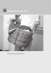
''THERMOSTAT
For convenienceandeconomyall MiniMax heatersare
equippedwith two thermostatson the front ofthe heater
control Danel.
POIVM
PRESSI"IRE
E]
E]
."-W
X
Y
4
Hor\...-
i-lcoto
[
Y
P@TIEMPERNLJAE
HEAI
HI-UMI
E ) @
.."A-///
X
Y
4
HOt\....-
Y
[
KNOB STOPPER''
Eachthermostatis equippedwith a mechanicalstop(Fig. 4)
thatcanbe lockedwith useofa screwdriver
to Drevent
temperatures
in excessofthat desiredby theuser.
The maximumsettingcan be adjustedby looseningthe
screw"A" andtuming the stopperdial to desiredmaximum
setting. Lock the settingby tighteningthe soew.
Y
/_,/C!tD
SPAIEMPERAruRE
Fig.3
t
The Pool/Off/Spaswitch allows the heaterto be tumedoff
whenheatingis not desired.
l.
"Pool"positionMaintainsselected
pooltemperature.
2.
"Off'position -
Heaterwill not comeon regardless
of
drop in pool temperature.
3. "Spa"position- Thisallowsseparate
controlofspa
waler temperature.
SELECTORDIALS
The selectordials eliminateconstantthermostatadjustments. Setthe spadial at the desiredspatemperatureand
thepool dial at the desiredpooltemperature.Thisprovides
convenlentpresetoperatrngtemperafures.
KnobStopper
Fig.4
I
OVERHEAT
THERMOSTAT
A manual re-set overheat thermostat is fitted adiacent to the
flow header. Ifthe appliancewill not light. before contactrng a serviceengineer,pressthe re-setbutton (Fig. 5) once.
Ifthe overheat condition persists, or is repeated, contact
your serviceengineeror gas supplier.
POOL
H -AIER
SECTION,PG.5
INSTALLATION
- WaterGonnections
INSTRUCTIONS
INSTALLATION
Caution: Exercisecarewheninstallingchemical
feedersso as to notallowbacksiphoningof
chemicalintoheater.filtersor DumD.
NonCombustibleflooring
Accessibility
o
To assureeasy
access,plumbing
shouldnot be
installedover the
top ofthe heater.
The water lines
shouldcome
directly into the
heaterfrom the side
or up &om the
Accessbflity
Fig.I
Note: Heatermustbe installedon a non-combustiblefloor
andat leastsix inchesfrom any combustiblematerialor
wall. Before installingwater pipe, checklocal building
codesrelatedto poolheaters.
Heatersinstalled below water level require
adjustmentof the pressure switch.
ri9.7
BelowPool Levellnstallations
Wherea pool heateris to be installedbelow the water level
switchto
to readjustthepressure
ofthe pool,it is necessary
pressue
in
system.
the
allow for the constantwater
GatevalvesshouldNOT be installedon the retum line
l. Backwashfilter and cleanthe pump hair and lint basket
beforemaking any adjustmentto the pressureswitch.
2. Tum on the circulationpump switch, the heaterpower
switchand setthe thermostat(s)to the hottestsetting.
3. Tum the pressureswitch adjustrnentknob clockwise
until the heatertums off.
4. Turn the adjustknob 1/4 tum counterclockwise. The
heatershouldcomebackon,
5. Tumthepumpoff. Theheatershouldshutoffwith the
circulationpump. Ifno, repeatsteps2, 3 and4.
6. Us€the circulationpump switch to tum the heateron and
off severaltimesto insureproperadjustments.
flom the heater. When the heater is installed below pool
level, install a check valve after the heater and a gate valve
between
Note:lf pool is more than 1 fr. aboveheaterorvice-vErsa,the pressureswitch may haveto be replacedwith a flowswitch,
SECTION,PG.6
INSTALLATION
- WaterConnections
INSTRUCTIONS
INSTALLATION
ReversibleInleUOutletConnection
with right
TheMiniMax is factoryassembled
side inlet/outletwater connections.The inleV
outlet headercanbe retersed for left sidewater
connectionswithout removingthe heatexchanger.
WaterConnections
Reversing
Disassembly
Toolsneeded:
l/4" NutDriver
9/16" SocketandWrench
112 & 9/16"OpenWrench
R€OUlaOdwhen inslalladon B b.low wator lovel
R.qt|lrcd when flow ral.3 orc4d 120 gPm.
F i g .1 0
PlumbingConnections
L
2.
3.
4.
5.
6.
7.
8.
9.
Removethe inspectionplates.
Disconnectall wiresfrom the highJimit switches
exceptshortjumperwire. Theexactorderof
is not important.
disconnection
Disconnecttlre pressureswitch tube from the in/
out header.
Removethe temperaturesensingbulb from the inl
out header.Note: You maycut thewire bundle
tres.
Exchangethe in/outheaderwith theretumheader.
tubesealswith new
Replacethe heatexchanger
sealsprovided.
sensingbulb by passingthe
Installthetemperature
wiresthroughthe holeprovidedon the left sideof
bracepanel. Routewires tlrough supportbracket.
Install the pressureswitch tubing into the in/out
headerby passingit abovethebracepanel.
all high limit wires. The orderof
Reconnect
connectionis not important.Routethewires
sensor
throughthe sameholeasthe thermostat
wlres.
Reinstallthe inspectionplates.
The MiniMax heater has the unique capability of
direct schedule40.PVC plumbing connections. A
Quick-Flangehas been included with the MiniMax to
insureconformity with Purex Pool SystemsrecommendedPVC plumbing procedure. Other plumbing
connectionscan be used. The instructionson the next
pageshow methodsfor successfullyconnecting
plumbing to the inlet/outlet header,with the QuickFlange.
CAUTION': Before operutingthe heater on a net'
installdtion, turn on circulation puntp und bl2edall air
frcm thertUer using the air rclieJ valve on lop of lhefiIten
lluer shouklflow freely lhrough heater.
Do not operatethe heater unless water in
pool/spa is at ProPerlevel.
ManualBy-Pass
Where the flow rate exceedsthe maximum i20 gpm a
manual by-passshould be installed and adjusted.
After adjustmentsare made,the valve handle should
be removedto avoid tampering.
Plumbing
Valves
- When any equipmentis locatedbelow the overflow rim ofthe pool or spa,valves should be
placed in the circulation piping systemto isolate
the equipmentfiom the pool or sPa.
-
Model
150
250
400
Min.
Max.*
20
30
40
120
120
120
tDo not exceedthe maximum recommended
flow rate for the connectingpiping.
Check valves are recommendedto preventback
siphon.
Caulion: Erercise care when insralling chemicalfeederc
so ss lo not allow back siphoning of chemicalinto the
hester,liuen or pump.
Table 3
BelowPool Installation
Ifthe heateris belowwaterlevel,the pressureswitch
mustbe adjusted.This adjustmentmust be doneby
a qualified servicetechnician.
t
INSTALLATION
SECTION,PG,7
Installation
InstructionSheet
Quick-Flange
EachitiniMax Quick-Flange
Kit contains:
I - Quick.Flangeunit
2 - 2" Rubbergaskets
4 - 3/8 Bolts
2 - I l/2" Rubbergaskets
4 - 3/8"Washers
2 - Plasticsleeves
FOR 1 1/2' & 2' SCHEDULE
40 PVCPIPE
FOR1 1'2" & 2" COPPERPIPF
\Pip"
\Plastic
Sleeve
F i g .1 1
a
\
Gastet
1 . Insertplasticsleevesintothe "QuickFlange"inlet
andoutletopenings.
2 . Slip rubbergasketsoverplasticsleeves.
3 . Bolt the "Quick-Flange"
to theheader.
NOTE: Tightenthe bolts evenly!
Do not over tighten!
4.
Useplumbersroll or mediumgrit sandpaperand
cleanthe inlet/outletopeningsofthe "QuickFlange".Usethe samemethodto cleanthe PVC
pipe. The sandpaperopenwill breakup anygrease
or contaminantthat may not be cleanedawaywith a
primer.
Fig. 12
*
You "DO NOT"needthe plasticsleeves.
Insertpipe into inleVoutletopeningofthe "QuickFlange".
Slip therubbergasketoverthe pipe,usingthe 2"
rubbergasketfor 2" copperpipeor the 1 1/2"
rubbergasketfor I l/2" copperpipe.
Bolt the "Quick-Flange"
to the header.
glue)andfollow
5 . Use711 PVC (or comparable
manufacturer's
recommendations.
Apply to the
"Quick-Flange.
inlet openingof the
Do the sameto
the PVC pipeandquickly insertpipeinto "QuickFlange"andtwist pipe l/4 turn. Do the sameto the
otheropeningof the "Quick-Flange".
6. For 1 j./2" PVC pipeinstallations,
first gluea I 1/2"
x 2" sch40 PVC bushing(not suppliedor shown)to
endofpipe prior to gluingto the "QuickFlange".
F i g .1 3
3/8'- 15
x2'LG
INSTALLATIONSEGTION'PG' 8
: Water
lHSrnlmTlONINSTRUCIIONS
4. Removeretum header'
Connections
lnleUOutlet(jonnecrlons
Reversiblelnleuoutlet
The MiniMax is factory assembledwith right sideinleV
outlet water connections'The inleVoutletheadercanbe
reversedfor left sidewater comectionswithout removurg
the heatexchanger.
1. Removethe insPeqtionPlates'
a
5. Switchthe in/out headerwith the retum header'
Replacethe heatexchangertube sealswith new seals
provided.
6. Install the temperaturesensingbulb andhi-limit
wires by p'assingthem throughthe hole provided on
the left sideof front Panel.
2. Disconnectall wires from the highlimit switches
exceptshortjumper wire. Disconnectthe pressure
switch tube fiom the in/out header' Removetle
temperaturesensingbulb from the in'/outheader'
rl
7. Reconnectall high-limit wires. The order of connection is not importart Routethe wles throughthe same
hole asthe thermostatsensorwires' Rerouteand install
the pressweswitchtubing behindthe control box and into
the in/out head.
3. Removein/outheaderbolts.
plates.
8. Reinstallthe inspection
{
INSTALLATION
SECTION.PG.9
- Outdoor
INSTALLATION
INSTRUCTIONS
The heatershouldnot be installedcloserthan 6 inchesto any
fences,walls or shrubsat any side or back,nor closerthan 18
inchesat the plumbing side. A minimum clearanceof24
inchesmustbe maintainedat front ofheater.
-
f f i * ffi
M E ffi
Do not installtheheaterin locationswhichwill permitthe
accumulation
of leavesor othercombustible
materialaround
thebaseofthe heater.
Do not installtheheaterin a locationthatwill allow
sprinklers
to operate
neartheheaterequipment
sincethe
watermaycausedamage
to tle controlsand./or
elecfonics.
Do not install directlyunderanyroofmountedgutter.
Do not install the heaterunderan overhangof less
thanthree(3) feet from the top ofthe heater. The area
undertheoverhangmustbe openon threesides.
Overhangsmustbe suchthat flue productsarenot
divertedinto living spaces.Heatersinstalledunder
overhangsmustbe protectedfrom direct roofwater
drainageby guttersandthe like. From the point where
the flue productsleavethe heater,that point MUST be
a minimumoffour (4) feetbelow,four (4) feethorizontally from or one (1) foot aboveany door, window
or gravity inlet to a building.
Fig. 1 5
IMPORTANT: Whenlocatingthe heater,considerthathighwindscan rolloveror deflectoff adjacent
buildingsandwalls. Normally,placingthe heaterat leastthree(3)feetfromanywallwill preventadverse
condiiions.lf it mustbe installednextto a wall.consultvourPureli/Triton
dealerfor advice.
INSTALLATION
SECTION,PG.10
- Indoor
INSTALLATION
INSTRUCTIONS
FlueRequiremenG
Air SupplyRequirements
A flue extensionofthe samesizemust be connectedto the
draft divertor andextendedtwo feet aboveany obstacle
within a I 0 foot radius ofthe flue. The flue shouldthen be
fitted with a suitableterminal.-.NOTE: Do not alter the
heaterdraughtdivertor in any way; it hasbeendesignedby
tle manufacturerandapprovedby British Gasplc. To
ensureefficient flueing, use45" Elbow for horizontal
installationwhen attachingflue pipe to draughtdivertor.
Whena heateris installedindoors,two air openingsmust be
provided. Oneopeningshouldbe placedat the bottom and
oneat the top ofthe room to allow for a free flow ofair. If
othergasappliancesare installedin the sameroom, you must
checkto seethat they havebeenprovidedwith the proper
sizeopenings,otherwisethey may usethe air intendedfor
vour Doolheater.
VentilationRequirementsArea
By Insrall€r
Model
Nal
Fig. 16
A quickcheckofyour flue installation.Allow heaterto
operatefor 15minutes. Then strike a woodenmatchand
blow out the flame. With the matchsmoking,hold next to
the draughtdivertor. Ifthe smokeis pulled up into the flue
andout of the room, the flue is correct. If it doesnot, you
mustmakeflueinsconections.
150
250
400
All air fromoutside
HighLevel
Low Level
Cm' (sq.in.)
Cm' (sq.in.)
270
300
400
A2\
(46)
(62)
540
600
800
(84)
(92)
(124)
Table 4
It is essentialthat the ventilation is direct from outside. The
appliancemustnot be installedin a room dfuectlyor
indirectly connectedto a living space.
Fig.17
INSTALLATION
SECTION.PG. 11
- AssemblingDraughtDivertor
INSTALLATION
INSTRUCTIONS
Placedrafthood adaptor over flue collector.
Securewith screws.
Parts: Draught Divertor
Adaptor
Top Cover
lnstall cover.
Removestackless top.
d
Placedraught divertor over adaptor secure
with screws.
INSTALLATION
SECTION.PG. {2
- GasGonnections
INSTALLATION
INSTRUCTIONS
PipeSizedFor LengthOf Run In EquivalentFeet
Before installing the gas
line, be sureto check
'U2"
3t4"
t"
what gasthe heaterhas
Model
Nat LP Nat LP
Nat
LP
beendesignedto bum.
10' 40' 50' 150' 150' 600'
This is importantbecause 1 5 0
different typesof gas
requiredifferent gaspipe
250
l0' 20' 50' 70'
1s0'
sizes. The rating plate orf
theheaterwill indicate
400
10' 20'
60'
which gasthe heateris
designedto burn. Table 5
showswhatsizepipe is
requiredfor the distancefrom gasmeterto the heater. The
table is for natural gasat a specific gravity of .65 and
propaaeat specificgravityof 1.5.
Whensizing gaslines, calculate3 additionalfeet of straight
pipe for every elbow used.
Wheninstalling the gasline, avoid gettingdirt, greaseor
otherforeign material in the pipe asthis may causedamage
to the gasvalve, which may result in heaterfailure.
The gasmetershouldbe checkedto makesurethat it will
supplyenoughgasto the heaterand any otherappliances
that may be usedon the samemeter.
Thegasline from the meterwill usuallybe ofa largersize
than the gasvalve suppliedwith the heater. Thereforea
reductionof the comectinggaspipewill benecessary.
Makethis reductionascloseto tle heateraspossible.
Theheaterandanyothergasappliances
mustbe disconnectedfrom the gassupplypiping systemduring any
pressuretesting on that system(greaterthat l/2 PSIG).
The heater and its gas connection must be leak tested
before placing the appliancein operation. Do not use
flame to test gas line. Use soapywater or other
nonflammablemethod.
A manual main shut-offvalve must be installed
extemal to tlte heater.
It is essentialthat the naluralgas
applianceis suppliedwith a governed
gas supply.
Do not installgas line union insideheater
cabinet. This will void your warranty.
I 1t2"
1 1t4"
f"
:'
250' 500'
v
LP
600'
100' 150' 200' 450'
Table5
l
INSTALLATION
SECTION.PG,13
- Electrical
INSTRUCTIONS
INSTALLATION
Electrical- ElectricalRating 230V AC 50 Hz fused at 5A
Note: lf any of the originalwiringsuppliedwith
is appliancemust be replaced,installermust
supplyNo. '18AwG 105 'C., approvedlow
energystrandedcopperwire or it's equivalent.
Caution:The heatermust be electrically
groundedand bondedin accordancewith local
codesor, in absenceof localcodes,with the
latestnationalelectricalcodes.
to themainsupplyvia a fuseddoublepoleswitch,havinga 3mm (l/8 in) contactseparaThisappliancemustbe connected
poles,
heater,pump,andanyextemalcontrols.
serving
only
the
tion in both
Wiring shouldbe a minimumof PVC insulatedcablenot lessthan2410.2mm to BS 6500table16.
to BS 1362.
All fusesmustbeASTA approved
Connectthe maincableto the terminalblockon LHS ofappliance(seewiring diagram),andclampthe cablein position
usingthe cableclampprovided.
ThisapplianceMUST be EARTHED.
THEAPPLIANCE
GOMMISSIONING
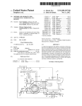
NaturalGasModelsOnly: ManifoldGasPressure
thenlight the appliance
asdescribed
in theUser'ssection,andcheckthebumer
Testthe installationfor gassoundness,
manifoldpressure
asfollows:
Turn thepowersupplyOFF.
to thebumermanifoldtestpoint.
Connecta manometer
Light the heaterandallow it to run for l0 minutesto stabilizethe bumers.
heatersize. The locatiol
adjustit to the figureshownin Table3 for the appropriate
andif necessary,
Checkthepressure
settingadjusteron thegasconfol is shownbelow. Removethe dustcoveroverthe adjustand,
of themanifoldpressure
to decrease
the pressure.
or anti-clockwise
tum the screwbeneathclockwiseto increase
usinga smallscrewdriver,
gauge,tightenthetestpointscrew,thenre-lightandtestfor gassound5. Turn the applianceOFF,removethepressure
ness.
1.
2.
3.
4.
Prossur€
adjustln9Scrcw.
(Undemoalh
dusl cove4
t-
INSTALLATIONSECNOil, FG.
- ElectricalGircuit
INSTALLATIONINSTRUCTIONS
Es
fiE
SERVICESECTION,
PG.15
- To be conductedonly by a qualifiedProfessional
MAINTENANCE
Maintenance
Instructions:
It is recommendedthat you checkthe following at least
gverysix monthsand at the beginningofevery swimming
sea:ion.
appearsyellow, bumersshouldbe inspectedand
cleaned.
4. Keepthe heaterareacleanand free from combustibles
andflammableliquids.
L Examinethe Flue system. Make surethereareno
5. Checkwire endsandwire connections.Thevshouldbe
obstructionsin the flow ofcombustion andventilating
cleanandtight.
air.
6. Checkthe bumer manifold pressureas describedin the
previoussection.
2. Inspectthe heatexchanger
for soot. Cleanasnecessary.
3. Visuallycheckthe burnerandpilot flame. Whenflame
BlueFlame
112in.
9 r l 2 m m
Insulated
Electrode
F i g .1 9
Springand Autumn Operation
Ifthe pool is beingusedoccasionally,
do not tum theheater
completelyoff Setthe thermostatdown to 65 " F. This will
keepthe pool andthe surroundinggroundwarm enoughto
bdng the pool up to a comfortableswimmingtemperaturein
a shorterperiodof time.
ReliefValve
In someinstallationsa reliefvalve is requiredon the
MiniMax.
Winter Operation
t
Ifthe pool won'tbe usedfor a monthor more,tum theheater
of at themaingasvalve. Wherefreezingis possible,it is
necessaryto drain the water from the heater. This may be
doneby openingthe drafurvalve locatedat the inlevoutlet
headerallowing all water to drain out of the heater. Use
compressed
air to blow thewaterout ofthe heatexchanger.
Also, disconnect
the pressure
switchfrom its l/4" copper
line. Thiswill preventfreezedamageto the switch.
Note: Uncirculatedwater trapped in the heater can
result in freeze damage to the heat exchangeror
headers. Freeze damage is specificallynot covered by
the warranty.
Caution: lf the heater has been drained for freezing
condition, do NOT turn "on" until the system is
circulation water,
Relief
Valve
- -j--i
Maybe
requiredfor
ASMEor
_ _ _ J
PG.16
SERVICESECTION,
MAINTENANCE
Soot Formationon the HeatExchanger
UsualCausesof Sooting:
5.
Reolaceburnersand test fue heatet
1.
Powdereddetergentand scrub brush accompaniedb1
high water pressureto spray the heat exchangerthoroughly.
2.
A very mild acid and water solution and high water
pressure. When using acid, gxcise extremecautlon so as
no to etch or damagethe copper tubing.
1 . Low gas pressurein the gas supply line.
Excessivewater flow ca.ncreatecondensationwhich
can causea soot formation.
3.
Foreign material in bumers and orifices. (Remove
foreign material such a! dirt, spider webs, etc.)
4.
lnadequateair supply for the heater,when installed
indoors, can causea soot formation.
Note: Afterde-sootinga heater,the flameshouldbe
bluein color,NOTYELLOW.Dustin theaircanturn
theflameyellow.A slightyellowtipon a blueflameis
oK.
To removea light soot formation,with the heat
exchangerstill in the heaterusethe following
procedures.
l.
Remove the burners and cover the orifices to protect
againstdirt or other material.
Remove flue collector and baffles.
!
InspectingThe HeatExchangerTubes
(HeatExchangerin Place)
Under normal operatingconditions the MiniMax heaterwill
operat€for yearswithout scaledepositsforming in the tubes'
In somepocls,however,the nineral contentofthe water is
suchthat completely scale-lieeoperation is next to impossible. For this reason,the MiniMax pool heaterhas been
designedso that the heat exchangercan be easily inspected
without disassemblingthe entire unit. Inspection ofthe
tubes at regular intervals is good assuranceof longer life and
lessmaintenance. To inspectthe tubes for scaledeposits,
use the following procedure:
l.
Remove inspectionplate.
2.
Remove the four (4) bolts holding the retum head in
Place-
3.
Removethe retum head and visually inspectthe tubes
4.
Replacetube gaskets.
3 . Using a brush with a long handle,you may brush off
the bottom ofthe tubes,which will generallyremove
any soot present. You may chooseto use a vacuum
cleaner.
airto
Note:Do Not useWireBrushor compressed
removesoot.
4.
Brush off and clean all burner headsusing cautionnot
to damagebumer Ports
To protecteyesfrom soot or cleaningsolutionuse safetyeyewear'
\-
PG.17
SECTION,
SERVICE
- RemovingThe HeatExchangel_
MAINTENANCE
whichcannotbe successfullyremovedby merelybrushingor use of a
For heavysoot accumulation
vacuumcleaner,the heatexchangermust be removedfrom the heater.
l. Turn off maingasto heater.
2. Turn pumpoff. Be surethatthe stopson theclockwill
or
not allowthe pumpto comeon duringinspection
is removed.
while the heatexchanger
3. Removelhetop fiom theheater.
t
7.
Removethe heat exchangermount screwson the side of
the heater.
*E ,*
4.
Remove inner lid, flue collector and inspectionpanels.
out ofheat€r.
8. Lift heatexchanser
o
5 . Disconnectthe plumbing at the break away flangesand
the pressureswitch line. Remove the thermostatbulb
and hi-limit wires ftom the inlet outlet header.
outof thefire
Caution:Whenliftingheatexchanger
brick,usecautionso as notto damagethefirebrick.
PG.18
SECTION,
SERVICE
MAINTE
l.
Inspectfile box for damageor cracksthatwould allow
heatto leak out into the outercabinetard controls'
5. Reconnectthe inlet andoutlet flangeto the headers(use
new flange gaskets)carefulnot to move the heat
exchangerandbreaktlte seal.
1
&
"a
:.,.1
: ir'
'
:ti
x
'....-.j$
Removeany old sealantfrom fire box.
6. Reinstallflue collector,inner panelandtop'
3 . Apply new sealantto the fire box (SiliconeRubber
trJustrial Graden.T V.) or equivalent The sealant
must completelysealthe spacebetweenthe heat
exchangerand fire box, so that whenthe heatersis
firing, heatdoesnot escapeto the outercabinet'
fi&.-.="'*.,.,.
{
4.
Place heat exchanger into the box and push down
ffmly, until the heat exchanger sets solidly on the fire
box.
t -
SERVICESECTION,
PG.19
- BurnerTrayRemoval& Disassembly
MAINTENANCE
At some time during the life of a heater,you may need to
inspect and repair the parts ofthe heaterthat allows the gas
to flow from the gas supply line into the bumers. Ifthe
heaterwon't fire and you wish to check thesegas controls:
l
9. Removethe bracketthe bracketthat holds the bumer in
place.
Turn off gas supply.
2 . Disconnectthe gasunionat the heater.
10. Removeeachbumerandcheckfor any blockages.
3 . Removethegasline installedinto thegasvalve.
4 . Removegasvalve holding bracket.
5 . Removegasvalvewires.
6 . Disconnect
the ignitionwire.
7 . Slidethe bumertray out.
tr
o
t 1 . Removethe main bumer orifices and checkfor any
blockase.
:.'..'.
3;:rr*-,-.
8 . You can remove the gas valve ifyou needto check the
inlet and outlet screens.(You will have to remove pilot
tubing.)
Note: lf the heaterhasbeenoff for the winteror
hasbeeninstalled,but notfiresfor an extended
periodof time,insectwillcrawlintotheseorifices
andthe ptlotorificeand preventthe heaterfrom
firing.
PG.20
SERVICESECTION'
12. Removethepilot orificeandcleanit (do not useany
sharpobject! It will destroythe designedorificesizel)
'., ,,
._'
of thehightensionignitionwire is veryimporInstallation
the bumertray into the heater'Thc
tantwhenreassembling
ontotheignitioncontroller
ignitionwiremustbe pushed
;cuit boardtightly andcompletelyto assurepropersparkat
theDilotelecfodeduringheaterstart-up'
' r'll
r'1*-'r
., ::
.:f ..:,,
1r'*
t,ri
:'
: ,
'.
.;:
.t
,r
. ,
I'
..
Mainburnerorifice:
Natural largeoPening
PropanesmalloPening
Orificesize: MM
Natural
0-4,000ft.
3.5mm(#29)
4,000- 6000ft
3 lmm (#31)
1 3 .After all control deviceshave beenremoved' clean manifold.
14. Reassembleparts and piecesand reinstall bumer tray.
il youhaveto
Note: Youcanusethisprocedure
or visa-versa'
fuelbpe flaturalto propane
chanee
to converttheMiniMaxare:Gasvalve,
Theiarts needed
mainburnerorificesandmodule'
pilotassembly,
SERVICE
SECTION,
PG.21
TROUBLESHOOTING
HEATERWILL NOTCOMEON
Possible Gause
a
Remedy
Automaticignitionsystemfails
are correctand
Checkif eletricalconnections
securelyfastened-lf YES,callserviceman.
Millivoltignitionfails
Checkto see if pilotis lit. lf not referto
"Operating
- Millivolt.
Lightinginstruction"
Pumpnotrunning
Placepumpin operation
Pumpair locked
Checkfor leaks
Filterdirty
Cleanfilter
Pumpstrainerclogged
Cleanstrainer
Defective
wiringor connection
Repairor replacewires
open
Overheatthermostat
Manuallyresetbuttonon thermostat
Defectivepressureswiich
Replaceswitch
Defectivegas controls
On - Off switchin "Off' position
Callserviceman
Turnswitchto "Pool"or "SDa"
HEATERSHORTCYCLING(RAPIDON AND OFFOPERATION)
Remedy
PossibleGause
t
Insufficient
waterflow
Cleanfilterandpumpstrainer
wiring
Defective
Repairor replacewiring
flowvalveor out of adjustment
Defective
Callserviceman
hi-limitand/or thermostat
Defective
Callserviceman
NOISES
HEATERMAKESKNOCKING
MAKESUREALL VALVESON SYSTEMARE OPEN
Possible Cause
Remedy
Heateroperatingafterpumphasshutoff
Shutoff gassupplyandcallserviceman.
Heaterexchangerscaled
Shutoff gassupplyandcallserviceman.
PG.22
SECTION,
SERVICE
TING - H
OUBLES
terminal or
With the othervoltmeterlead,touch each
switchandhigh
.onnJon on tft" tftermaloverload,pressure
switches'
i-lt". ituortug" i. pres€nton both sidesofthese
they are oPeratingProPerlY'
and
lfvou havea good sparkbetweenpilot assembly
on'
power
turn
elecrode, push elecffodeback on pilot and
pilotis oK If no
ii-v* i"ti g*a tparkatpilotelectrode,
sparkorweaksPar:
lgnitionControllerSParkTest
tumpowerOFFandremove
Ifthereis stillnopilotsPark,
i*"i i"" *it" t ""i ignitioncontrollercircuitboard(ICCB)'
power
iold wire terminalcloseto ICCBterminalandtum
spark
1/8"
oN. ificcn is good,therewill bea srong
weakor
i"t*""" rccs u;o ignitionwte' If thesparkis
theICCB'
rePlace
thereis no sPark,
r.\',
:
is attachedto thebumerclean
A. Makesurepilot assembly
andtight to createa goodground'
B. Makesureceramicinsulatoris not cracked'
spark'replace
C. Makesur€electrodeis clean lf still no
pilot assembly.
D. Makesuresparkgapis setproperly'
.t
I
,, l&. I L
3mm
i/8"
wire terminal'
Ifthere is a goodsparkbetlveenICCB and
on to the
back
wire
,o- oo*". 5ff undpushignition
fiom
assembly
iCii. pul ig"ition wire andelectrode
replace
damaged'
is
oifot. Cft""tionation ofwire, if it
is OK'
i*nliio" tnit"l.f""t ode. If ignitionwire/electrode
good
lf-a.
on
power
rt""iJ"r"t" L p * "ssemblyandtum
wire
pilot
assembly'
tr"tt it ot..* U"*een eiectrodeand
assembly'
ii or, iino tp*t, .eplacewire/electrode
Fig.22
I
- HeaterWon'tFire- PilotOn TROUBLESHOOTING
l.
Check"all" wire connection
to controlandpround.
Theyshouldbe cleanandtight.
4. Checkvoltageat gasvalves(redwire). If voltageis
presentandheaterdoesn'tflre, replacegasvalve.
Checkvoltageat both terminalsofthermal cutoff,
pressure
switchandhi-limit. Ifvoltage is presenton
bothterminals,thesecontrolsareOK.
Note: Beforereplacinggasvalvemakesure
mainburnerorificesareclean.
3 . Checkvoltageat ignitioncontrcllercircuit
board(ICCB).
Ifno voltagepresentat red wie, replaceICCB.
-
- HeaterCyctesRapidtyTROUBLESHOOTTNG
Do Not ReplaceAny Controls Before
ReadingTheselnstructions!
Preliminary
checks:
l.
Make surepump is primed andyou seeadequate
water flow.
A. If the water level in the pool is low, the pump
will loseprime andreprime itself causingintermittentflow to heater,causingcycling.
B. If the filter is dirty, the water flow may fluctuatecausingpressure
switchto cycle.
C. If wind blows pilot flame away from elechode
mainburnerwill cycleon andoff.
D. Ifflow valveis inoperative
theheaterwill
cycle.
Note: Turn poweroff. Placejumperwire across
the high limit(s). Turn poweron. Ifheaterstops
cyclingproblemis the waterin headeris too hot or
high limit(s)is defective.Ifheatercontinues
to
cycle, problem is in wiring, groundingor another
control.
Checkwiring connections
to gasvalve; arethey
cleanandon correctterminals.
: :cck ignitionwire fiom ICCBto pilot assembly.
i
Ii isnitionwle is looseat ICCB,heaterwill
3 t:3cl all sroundconnection.IID heaterswill
:r... 3r.j op€rateerraticallywhennot properly
::oorded
To checl rster relatedcycling
Checkfor correctheaterflow ffom table3, page6.
If lessthanminimumrequiredfor model,the waterwill
overheatandcausehi-limit to cycle
5 . Thewatertemperature
will alsoriseto 1500Finsidethe
headerifthere is too much restrictionin the piping between
the heaterandthe pool. This causesthe water to slow down
asit passesthroughthe heatexchanger.The combustion
temperatureremainsconstant,so if the water speeddecreases,the temperatureincreases.
Ifwater is overheating,you can checkactualtemperature
insidethe headerby installing a heaterthermometerwhere
thehosebib is now installed.Thiswill tell you ifthe
temperatureis abovethe hi-limit will shutthe heateroffand
then whenthe watertemperature,the hi-limit will allow the
heaterto re-fire. This rapid cycle will rangefrom 15to 45
seconds.
Note: Temperatureinsidethe headeris controlledby the
flow valve. If the water flow is low or closeto minimum
requirements,the flow valve forcesmost ofthe water into
the heatexchangerkeepingthe temperatureinsidethe
headerat an efficient level arrdbelow hi-limit shut off
temperature.Ifthe water flow is moretlan enoughor close
to maximumgallonsper minute,the flow-valve remains
relatively unaffectedandallow enoughwater to by-passso
that the temperatureinsidethe headerstaysat an efficient
level.
Conclusion:Ifthe flow valvewasinoperative,
thetemperatureinsidethe heaterwould reachhi limit shut off
temperatureandthe heaterwould cycle rapidly. So after
you havecheckedthe electricalcontrolsfor badgroundor
wiring, checkthe flow valve. Note: The flow-valve is
locatedin the inlet/outletheader.
SERVICE
SECTION,
PG,24
- HeaterCyclesRapidly(con't)
TROUBLESHOOTING
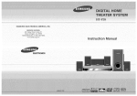
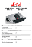
To check flow valve:
A. Remove flow valve fiom header.
l-
s 3ta
B. Checkfactorymeasurement:
3 3/4" fiom mounting
plateto the 2nd disc.(onsideexcludinggasket).
Note:
Discsmustbe parallelwith mountingplate.
I
C. Checkflow valvefor anyphysicaldamage.
D. Hold powerelementunderhot waterandseeif
powerelementmovesthe discstowardsthemounting
plate3.8"- 1i2".
E. Turn coldwateron,powerelementshouldretact
to originalfactorysetting.Ilflow valveexpands,
flow
retracts,andretumsto original measurement,
valveis OK.
Thepowerelementis thepartofthe flow valvethat
whenheated,movesthe 2 discsovertowardthe inlet,
forcing morewater into the heatexchangerandretracts
whenthewateris cold,allowingwaterto bypassor
retumto the pool,withoutgoinginto the exchanger.
Hereis a list ofthingsthatwill causethepowerelement
to lail andcausetheheaterto cycleon thehi-limit:
A. If thepH of thewateris too low, thepower
elementwill be eatenawayandwill not move.
is too high,thepower
B. Ifthe calciumhardness
elementwill becomecoatedwith calciumdepositsthat
will disablethe flow valve.
C. If powerelementhasbeeninstalledincorrectly.
D. If anydebrisin the circulationsystemwereto pass
by or throughthe filter andbecomelodgedin the flow
valvemechanism.
If water temperatureinside IS NOT 150 'F and, all
above testshave been completedand heaterstill
cycles,the hi-limits should be replaced.
mr
..,r**;iil
o
\
PG.25
tll{llllflE
:IER-ALt MODELS
IC
Fig.23
PG.26
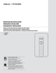
MiniMaxPartsList
1
Ventkit assembly(indoor)
1
75979
75980
75981
2
Returnheader
1
70994 70994
70994
3
Bracketwasher
2
74216 74216
74216
4
BoltHH 3/8"x 2"
4
73739 73739
73739
5
Bolt3/8'-16x11t2"
4
70416 70416
70416
o
Washer3/8"lD 1' OD
4
72180 72180
72180
7
Tubesealgasket
1 8 70951
6
- lD
lgnitionController(complete)
1
75865
70951 70951
/ cooc
75865
71134 71l3r'. 71134
1
71949
71949
71949
11
Thermostatknob
Switchrocker(doublepoledoublethrow)
- llD
Controlpanelassembly(complete)
1
/cvJo
75937
75938
12
Door- llD
1
73869
73868
/J6r)/
12.
Manifoldburner
1
70256
70257
70258
14
1
75864
7586/.
75864
15
Gasvalvenatural- llD
Pilottube- llD
1
75931 75931 75932
16
- llD
Bumertrayassynatural(complete)
1
75925
75926
75927
17
Bumer
3 EA.
5 EA.
8 EA.
70230
18
switch
Pressure
1
70230 70230
71580 71580 71580
19
chamberassembly(complete)
Combustion
1
73858
73857
73856
20
21
22
23
Valvedrain3/4"
"T' 3/4"brass- ASMEor localcode
1
72't34
72134
72134
1
71983 71983 71983
Valverelief3/4"5O#- ASMEor LocalCode
1
72138
Nipple3/4"
1
71388 71388 71388
Flowvalveassembly(complete)
I
73841
73841
Flowvalvegasket
Bolt3/8"- 16 x2112
4
74015
74015 740't5
2
75492
75492
75492
QuickflangeKit- fits 1.5or 2" installation
Sleevein/out2"
1
75284
75284
7528/.
2
71895
71895 7 1 8 9 5
Bushing
in/out
2" (rubbeo
70544
70544
70544
Bushing2" to 1 1/2"(rubber)
70229
70229
70229
I
10
25
26
27
28
72138
72138
73841
30
SafetyShutoff
2
71017 71017 7't017
3'1
OverheatThermostat
1
75875
75875
75875
PG,27
MiniMaxPartsList Gont.
1&r: '''2
E
D-
D
ft
ne-r
Gl'tgrr
-r3s -*j:s
llr
ra
9||!'e
-
rtr
b.
- -j'ie{
a
74451
74074
8ea
8 ea.
16ea.
tulto
70278
Th€nrpstat
-3864
73782
2
' Not Shown
Plasticmounting
bracket
Wireharness(gasvalve)- llD
JumperAssy.
73863
73862
73781
73780
72022 72022 72022
70715 70715 70715
75877 75877
75877
ScrewSxl/4"HH
75890 75890 75890
71703 71703 71703
ScrewSxl/2"HH
71698 71698 71698
Screw6 x 1/4"
Screw10-32x '1l4"
71716 7 1 7 1 6 71716
71659 71659 71659
Screw10-32x 3/16
75692
/ covz
70551
70551 70551
1
Bushing
1/2"
)
74452
73810 73810
'
ac :er€:. er'a.€
3€
70985 70985
:- a:':
=lco
f,g-u.,-
70985
I COVZ
Thermknobstopper
Wre harness(control
box)- llD
..'
71940 71940 71940
1
75878
lgnition
cableWelectrode
Powerelement(flow-valve)
1
75869 75869 75869
1
73656
Bolt5/16"- 18x 3/4'
75878
75878
73656 73656
73725 73725 73725
3
c
6
N
N
N
Orificemainburnernatural
- llD
Pilot- natural
71465
71465 71465
LineFilter
75879
75879
Thermalcutoff
75173 75173 75173
71465 71465 71465
75879
Glossary
PG.28
Burner - A devicefor
finar conveyanceofgas,
ftf,1ootooo
- The rapid oxidation
combustion chamber -
or a niixfure ofgas and
air, to the combustion
zone.
offuel gasesaccompanied
by rheproducrionofheat
Theportionof anappriance
within
or hearand
whichcombustionnormalry
occurs.
-,O*tces designed
ro regutatethegas.air,
fff::I
wate
^'ter or electricitysupplied
I neymay bemanual.
semiauromaric
to a gasappliance.
o. arto;;;;"
Downdraught_Excessive
I
pressueexistins
gasesflow d;ffi;;Jif"lff
3f^t: ltl"T""
at theoutletof chimneyor
stackwith rensto make
_-Adevicebuihinro
anapptiance.
or made
:Ti*"r#,:tltu
r*1l#l':i"T,i",JmnT:x$lixijll;n*:""?ii:-
ano
(r)neurarize
the
errecr
orsrack
acrron
or" ;il;;;"Jll fiffi
Electronic
ThermostatsCor
lr :o.IT ; ;; ;; ;; o'ilHtff
,T::rH.,x;h:*##j.
".- r,poten
riomerer
an
dcircuir
,Iff;,:?;l,j:.10 isto
a
H:*HiTilU,myi:U:
::::::iT*:'",r-'o:t"ii;'i;#:'Jii.fi
:,lf"t'l'llff,
rance
reveri, "rrrbri;;;;:;;.'.,'n"
1on."ptis thatby rumi
thewaterchangesil;:;#:
j1m*miffilfi
IY
y:lr.
l'"*:1i:T[:T::.,'#:'?H;":.,T;.
Installedin theinter/ourlet
header;whenthr
l;J,ffi*;ilfl,Tii',liT"l',""yXflilf,ffLfi:H'l*:ii:1*',',.
mperature
andminimizescondensation.
Ftue^producrs
products
_
'- of
-^ -v.ruu*rur
combustion
Ilr:j:1t
ers oetorethe draft hood.
andexcessair in appliance
anq
flues
or heat exchang_
Gas Valve - A device
that al
themain
bd;;;;ffifi,i:#
Heat Exchanger_Any
fi:i*TJ
suppry
rineintorhepirotassembry
andinto
devicefrom ftansferring
heat.
IllXilX'I"'#il:?r"";:"fl;.t1.*.:.':".:1ff
inlout
headerto
prevenr
r,,e
il,T#::1,-eorthe
circuir Board(tCcB) _Device
:::::f"S*jllter
control
rharsr
rhe ICCBstartsthepilot
-o."irit,or..;ffi::*t
ICCB IgnitionWire or
andreceives
signalsto otherhearer
Hi_T
tothe
ignition
contro,rercircuir
,x".il!':;"?,Ti#ig'ilhTi:Tliq'r{ll#;:,*:'ed
Drlot
lgnitor
and
back
: p or flame
to the ICCB to
is established.
signal
PG.29
(con't)
Glossary
Input Rating - The gas-bumingcapacityofan appliancein BTU per hour as specifiedby the manufacturer. Applianceinput ratingsarebasedon seallevel operationandneednot be changesfor operation
up to 2,000feet elevation. For operationat elevationsabove2,000feet, input ratingsshouldbe reduced
at therateof4 percentfor each1,000feetabovesealevel.
*LPG" and "LP Gas" meanand
Liquefied Petroleum Gases- The terms"Liquefied PetroleumGases"
include any fuel gaswhich is composedpredominantlyof any of the following hydrocarbons,or mixnormal butaneor isobutaneandbutylenes.
turesof them: propane,.propylene,
Manifold - The conduit of an appliancewhich suppliesgasto the individual bumers.
Natural Gas - Any gasfound in the earth,asopposedto gaseswhich aremanufactured.
Orifice - An openingin an orifice cap(hood),orifice spudor other devicethroughwhich gasis discharged,andwherebythe flow of gasis limited and/orcontrolled.
Pilot - A small flame which is usedto ignite the gasat the main bumer.
a pilot flamejust prior to ignitionof mainbumers.
Pilot Ignitor or Pilot Assembly- Establishes
PressureSwitch - A control that respondsto waterpressure.Whenthe heatersensesadequatewater
pressurethe heaterwill fires andwhenthe pressuredropsbelow 1 1/2 PSI at the switch, the heaterstops
firing.
Primary Air - The combustionsir introducedinto a bumerwhich mixeswith the gasbeforeit reaches
the port. Usually expressedasa percentageof air requiredfor completecombustionof gas.
Propane - A hydrocarbongasheavierthan methanebut light than butane. It is usedas a fue1gasalone,
mixed with air or asa major constituentof liquefiedpetroleum.
mostlyconsistingof smallparticlesof carbon,whichcanresultfrom incomSoot- A blacksubstance,
pletecombrrstionand appearas smoke.
Therm - A unit of heatenergyequalto 1000,000BTU.
Thermal Cutoff - A heatsensitivefusethat breaksthe powerto the controlsif the temperatureis too
high in the gasvalve area,causingthe heaterto switch off.
Transformer - A coil devicethatchanges
high voltageinto low voltage.
Flue - A Device,suchas a pipe, to hansferflue productsfrom an applianceto the outdoors, This term
alsois usedto designate
a smallholeor openingfor theescapeofa fluid (suchasin a gascontrol).
pressure.
Water Column - AbbreviatedasW. C. - A unit usedfor expressing