1
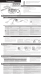
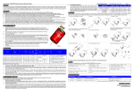
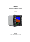
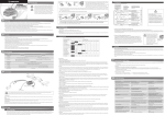
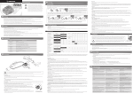
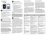
User Manual of QUICRUN Series Sensored Brushless Speed Controller HW-SM301DUL-20131007 Introduction Congratulations and thanks for purchasing the QUICRUN series electronic speed controller (ESC). The power system for RC model can be very dangerous, so please read this manual carefully. Since we have no control over the installation, application, use or maintenance of this product, in no case shall we be liable for any damages, losses or costs. 1 Turn on the transmitter, and set parameters (of the throttle channel) like “D/R, “EPA”, “ATL” to 100% (if there is no LCD display on the transmitter, please adjust the corresponding knob to its limit). Set the throttle trim to 0 (if there is no display, then adjust the knob to the neutral position). For TM FUTABA and similar transmitters, set the throttle direction to “REV”, while the throttle direction of others to “NOR”. Please disable the built-in ABS brake function in your transmitter. 2 Hold the SET button while sliding the switch to the ON position, and then release the “SET” button the moment when the Red LED starts to blink. (If you don’t release the SET button in 3 seconds, the ESC will enter the program mode, in such a case, please switch off the ESC and re-calibrate the throttle range again from Step 1.) Refer to the picture on the left side. Features High performance but low price, users can own this reliable race-ready ESC at an affordable cost. Compact size, suitable for various car chassis. Auto identification system can recognize sensored / sensorless brushless motors automatically. Excellent operating feelings and plentiful adjustment options, suitable for most kinds of competitions. 8 steps of timing adjustment greatly increase the output power of the motor, and unlock its maximum potential. Proportional brake with 4 steps of Maximum Brake Force adjustment, 8 steps of Drag Brake Force adjustment and 4 steps of Initial Brake Force adjustment. 9 steps of acceleration (punch) adjustment, from “soft” to “very aggressive” to fit for different kinds of cars, tires and tracks. Multiple protections: Low voltage cut-off protection for Lipo or NiMH battery / Over-heat protection / Throttle signal loss protection / Motor Lock-up protection. One-button (the “SET” button on the ESC) to set the ESC, and easy to reset all parameters to the factory default settings. Compatible with the optional device ---- the portable Digital LED Program Card, especially convenient for outdoor use. Specifications Model Cont. / Peak Current / Resistance Motor Type Supported Cars Applicable Motor Limit QUICRUN-10BL60-SENSORED 60A / 380A / 0.0008 Ohm 3 Set the 3 points according to pictures on the left side. ► The neutral point ► The end point of the forward direction ► The end point of the backward/brake direction When the process of calibration is finished, the motor can be started after 3 seconds Sensored / Sensorless Brushless Motor 1/10 & 1/12 On-road / Off-road / F1 / Drift car race Street race for fun / Club racing / Daily practice / STOCK race with 0 timing / Drift car race 4-6 cells NiMH/2S Lipo ≥8.5T(1/10 On-road), ≥13.5T(1/10 Off-road) 8-9 cells NiMH/3S Lipo ≥13.5T(1/10 On-road), ≥17.5T(1/10 Off-road) *Note 1 Battery BEC Output / Operating Voltage of the Cooling Fan Dimension / Weight Page 1 *Note 1 4-9 cells NiMH, 2-3S Lipo 6V@2A, Linear Mode / 6V (The cooling fan gets its power supply from the built-in BEC) 33mm(L)*28mm(W)*31.5mm(H, with cooling fan) / 59g (with wires, without cooling Fan) Note 1: “T” indicates the limit value of motor turns when the ESC timing is set to 0. The larger the timing, the more turns the motor needs. Please pay close attention to temperatures of the motor and the ESC to avoid any damage to these two equipments. Begin to Use the New ESC Step 1: Connect the battery, servo, receiver, ESC and motor according to the wiring diagram below, recheck all the connections before entering the next step. ★ Sensored motor wiring When using sensored brushless motor, please connect the “SENSOR” port of the ESC and the the “SENSOR” port of the motor with a sensor wire. Warning! For sensored brushless motor, the #A, #B, #C wires of the ESC MUST be connected with the motor wire #A, #B, #C respectively. Do not change the wires sequence optionally! ★ Sensorless motor wiring When using sensorless brushless motor, the #A, #B, #C wires of the ESC can be connected with the motor wires freely (without any order). If the motor runs in the opposite direction, please swap any two wire connections. Warning! Please disconnect the battery from the ESC after running the car! Step 2: Set the Throttle Range In order to make sure the ESC fits the throttle range of your transmitter, you must calibrate it when begin to use a new ESC, or a used transmitter if some of its settings have been changed, like the Throttle Trim, D/R, EPA or other parameters. Otherwise, the ESC cannot work properly. Besides, we strongly recommend users to enable the “failsafe” function of the transmitter, set the “F/S” of the throttle channel to the Shutdown mode or set the protection value to the neutral position, so the car can be stopped if the receiver fails to get the radio signals from the transmitter. Please calibrate the throttle range according to the following steps. Step 3: Check the LED Status in Normal Running 1) In general, if the throttle stick is in the neutral range, neither the Red LED nor the Green LED lights. 2) The red LED solidly lights when the car is running forward or backward and it will blink quickly when the car is braking. 3) The Green LED solidly lights when the throttle stick is located at the top point of the forward zone (that means full throttle is applied). Troubleshooting Trouble(s) Turn on the switch, no LED lights up, and neither the motor nor fan works. After power on, motor doesn’t work but emits “beep-beep-, beep-beep-” alert tone. (there’s 1-second pause between 2 “beep-beep-”). After power on, the Red LED turns solid red but the motor doesn’t work. The car runs backwards when accelerating forward on radio. The car suddenly slows down, then stops about 15 seconds later. The motor stuttering under heavy acceleration. Possible Causes No battery voltage is input to the ESC. The switch of the ESC is damaged The voltage of the battery pack is not in the normal range, it’s too high or too low. Solution(s) Check the connections between the battery and the ESC, re-solder the connectors if needed. Change the switch. Check the voltage of the battery pack. The throttle signal wire is oppositely inserted or into the incorrect channel. The wire connections between the ESC and the motor need to be changed. The chassis is not suitable for this ESC Low voltage cutoff protection (Red LED blinks) Overheat protection (Green LED blinks) Low battery discharge rate. The motor RPM is too high (i.e. the motor runs too fast), and the gear ratio is too small. The “Punch” setting is too high. Plug the signal wire (Rx lead) correctly into the throttle channel (usually Channel #2) of the receiver. Swap any two wire connections between the ESC and the motor. (Note: This method is ONLY available for SENSORLESS motor ) Please don't use the ESC for this special chassis. Check the battery voltage. If still has some capacity, lower the cut-off threshold voltage; if not, replace a new battery. Wait several minutes to cool the ESC. Increase the gear ratio or the T number (Turns) of the motor. Use a battery pack with better discharge ability. Use a low-speed motor, or increase the gear ratio. Set the acceleration (punch) to the softer mode. User Manual of QUICRUN Series Sensored Brushless Speed Controller Trouble(s) The car slows down and then stopped. The Red and Green LEDs blink rapidly and synchronously when throttle stick in neutral. The motor stutters and can’t start up. Possible Causes ESC detects abnormal signals from the sensor port of the motor and the ESC changes to sensorless driving mode automatically. The connections between the motor and ESC are not A-A, B-B and C-C; The ESC is damaged Solution(s) Check the sensor wire connection. The Hall sensors in the motor are damaged, please change the motor. Program the ESC Check wiring & connections. Contact the distributor for sales-after service. Programmable Items (Italics in the form below indicate the factory defaults) Basic Items Option 1 Option 2 Option 3 Fwd/Brk (For Racing) Fwd/Rev/BR Fwd/Rev (For Training) (For Crawling) 2.Drag Brake Force 0% 5% 3.Low Voltage Cutoff Disabled 4.Start Mode(Punch) Level 1 1.Running Mode * Option 4 Option 5 Option 6 Option7 Option 8 10% 20% 40% 60% 80% 100% 2.6V/Cell 2.8V/Cell 3.0V/Cell 3.2V/Cell 3.4V/Cell Level 2 Level 3 Level 4 Level 5 Level 6 Level 7 level 8 25% 50% 75% 100% 25% 50% 75% 100% 0% 20% 40% 6%(Narrow) 9% (Normal) 12%(Wide) 0.00 deg 3.75 deg 7.50 deg Option 9 Level 9 Advanced Items 5.Max.Drag Brake Force 6.Max.Reversing Force 7.Initial Brake Force 8.Throttle Range 9.Timing Equals Drag Brake Force HW-SM301DUL-20131007 Page 2 Reset All Items To Default Values At any time when the throttle is located in neutral zone (except in the throttle calibration or parameters program process), press and hold the “SET” key for over 3 seconds, the red LED and green LED will blink simultaneously , which means each programmable item has be reset to its default value. 11.25 deg 1 Set the ESC by Program Card The Program Card is optional equipment which needs to be purchased separately. It has 3 digital LEDs to display the programmable items’ number and the options’ number. It is portable and very easy to use. (For detailed information, please refer to the user manual of the program card). 2 Set the ESC by the SET button Please check the flow chat on the right side. 15.00 deg 18.75 deg 22.50 deg 26.25 deg * Fwd= Forward, Rev=Reverse, Brk=Brake Explanation for Each Programmable Item: 1 Running Mode: With “Forward with Brake” mode, the car can go forward and brake, but cannot go backward, this mode is suitable for competition; “Forward/Reverse with Brake” mode has reverse running function, which is suitable for daily training. Note 2: “Forward/Reverse with Brake” mode uses “Double-click” method to make the car go backward. When you move the st throttle stick from forward zone to backward zone for the first time (The 1 “click”), the ESC begins to brake the motor, the motor slows down but it is still running, not completely stopped, so the backward action is NOT happened immediately. When the throttle stick is nd moved to the backward zone again (The 2 “click”), if the motor speed is slowed down to zero (i.e. stopped), the backward action will happen. The “Double-Click” method can prevent mistakenly reversing action when the brake function is frequently used in steering. By the way, in the process of braking or reversing, if the throttle stick is moved to forward zone, the motor will run forward at once. “Forward/Reverse” mode uses “single-click” method to make the car reverse. When moving the throttle stick from neutral zone to backward zone, the vehicle reverses immediately, so this mode is usually used by rock crawler. 2 Drag Brake Force:Set the amount of drag brake applied at neutral throttle to simulate the slight braking effect of a neutral brushed motor while coasting. 3 Low Voltage Cut-Off: The function mainly prevents the Lipo battery from over discharging. The ESC detects the battery voltage at any time, if the voltage is lower than the threshold for 2 seconds, the output power will be reduced 70%, after 15 seconds the output power will be completely shut off and the red LED flashes in such a way: “☆-☆-, ☆-☆-, ☆-☆-”. Please stop your car at the track side as soon as possible to avoid obstructing other racing cars. Note 3: For NiMH battery, if the voltage of the whole NiMH battery pack is higher than 9.0V, it will be considered as a 3 cells Lipo battery pack; If it is lower than 9.0V, it will be considered as a 2 cells Lipo battery pack. For example, if a NiMH battery pack is 8.0V, and the threshold is set to 2.6V/Cell, so it will be considered as a 2 cells Lipo battery pack, and the low-voltage cut-off threshold for this NiMH battery pack is 2.6x2=5.2V. 4 Start Mode (Also called “Punch” or “Acceleration”): Level 1 has very soft start acceleration, while level 9 has very quick start acceleration. From Level 1 to Level 9, the start force is increasing. If you choose “Level 7” to “Level 9”, you should use good quality battery with powerful discharge ability, otherwise you cannot get the burst start effect as you want. If the motor cannot run smoothly (the motor is cogging), sometimes it is caused by the weak discharge ability, please use a better battery or increase the gear ratio. 5 Maximum Brake Force: The ESC provides proportional brake function. The brake force is related to the position of the throttle stick. Maximum brake force refers to the force when the throttle stick is located at the top point of the backward zone. A very large brake force can shorten the brake time, but it may damage the gears. 6 Maximum Reverse Force: Sets how much power will be applied in the reverse direction. 7 Initial Brake Force: It is also called “minimum brake force”, which refers to the force when the throttle stick is located at the initial position of the backward zone. The default value is equal to the drag brake force, so the brake action can be very smoothly. 8 Throttle Neutral Range: Please refer to the picture to adjust the neutral range. 9 Timing: This function can be used to fine-tune the output power of the motor, the bigger the timing, the faster the motor runs or the larger output power of the motor. As the Boost Timing technology has been introduced into this ESC, so under the sensored mode, adjust the ESC timing can greatly increase the motor RPM. Therefore, please remember to enlarge the gear ratio of the chassis and carefully check temperatures of the motor and the ESC after increasing the timing. Note 4: ► In the ESC setting process, the motor will emit “Beep” tone at the same time when the LED is flashing. ► If the “N” is bigger than the number “5”, we use a long time flash and long “Beep—” tone to represent “5”, so it is easy to identify the items of the big number. For example, if the LED flashes as the following: “A long time flash + a short time flash” (Motor sounds “B—B”) = the No. 6 item “A long time flash + 2 short time flash” (Motor sounds “B—BB”) = the No. 7 item “A long time flash + 3 short time flash” (Motor sounds “B—BBB”) = the No. 8 item And so on. Recommended Power System Motor KV Gear Ratio (1/10 on-road) Gear Ratio (1/10 on-road) Main Application QUICRUN-3650-10.5T-Sensored 3300 5.0---6.5 6.5---8.0 1:10 STOCK race / Drift car QUICRUN-3650-13.5T- Sensored 2500 4.0---5.5 5.5—7.5 1:10 STOCK race QUICRUN-3650-17.5T- Sensored 1900 3.5---5.5 5.0—7.0 1:10 STOCK race / F1 QUICRUN-3650-21.5T- Sensored 1600 3.5---5.5 4.0---6.0 1:10 STOCK race / F1 / Crawler Note 5: The reference gear ratios in the above form are based on the 1/10 RC cars with 2S Lipo and 0 timing ESC. If the ESC timing is increased, then the gear ratio needs to be increased accordingly. Besides, please pay attention to the temperature of the ESC and the motor to avoid any damage to the equipments. Hobbywing Technology Co., Ltd. http://www.hobbywing.com