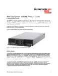
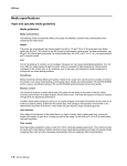
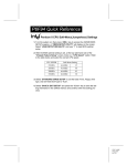
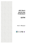
1
Award BIOS Setup Program
Chapter 3
3
Award BIOS Setup Program
Award's BIOS ROM has a built-in setup program that allows users to modify the
basic system configuration. This information is stored in CMOS RAM so that it
can retain the setup information, even when the power is turned off.
When you turn on or restart the system, press the Delete key to enter the Award
BIOS setup program. The primary screen as shown in Figure 3-1 is a list of the menus
and functions available in the setup program. Select the desired item and press enter
to make changes. Operating commands are located at the bottom of this and all
other BIOS screens. When a field is highlighted, on-line help information is displayed
on the right side of the screen.
CMOS Setup Utility- Copyright (C) 1984-2001 Award Software
Standard CMOS Features
Frequency/Voltage Control
Advanced BIOS Features
Load Fail-Safe Defaults
Advanced Chipset Features
Load Optimized Defaults
Integrated Peripherals
Set Supervisor Password
Power Management Setup
Set User Password
PnP/PCI Configurations
Save & Exit Setup
PC Health Status
Exit Without Saving
: Select Item
Esc : Quit
F10 : Save & Exit Setup
Time, Date, Hard Disk Type...
Figure 3-1 Setup Program Initial Screen
21
User's Manual
3-1 Standard CMOS Features
The Standard CMOS Features allows users to configure system components such
as hard disk drive, floppy disk drive and video display as well as date, time and
boot up error signaling. This configuration menu should be changed when installing
a mainboard for the first time, changing hardware in your system such as the HDD,
FDD, video display, or when the CMOS data has been lost or contaminated. Choose
the Standard CMOS Setup option from the CMOS Setup Utility menu (Figure 31) to display the following screen. When a field is highlighted, on-line help
information is displayed on the left bottom edge of the screen.
CMOS Setup Utility- Copyright (C) 1984-2001 Award Software
Standard CMOS Features
Date (mm : dd : yy)
Time (hh : mm : ss)
Mon, Feb 22 2001
17 : 14 : 44
IDE
IDE
IDE
IDE
None
None
None
None
Item Help
Menu Level
Primary Master
Primary Slave
Secondary Master
Secondary Slave
Drive A
Drive B
Floppy 3 Mode Support
1.44M, 3.5 in.
None
Disabled
Video
Halt On
EGA/VGA
All Errors
Base Memory
Extended Memory
Total Memory
640K
64512K
65536K
:Move Enter:Select
F5:Previous Values
+/-/PU/PD:Value
F10:Save
ESC:Exit
F1:General Help
F6:Fail-Safe Defaults
F7:Optimized Defaults
Figure 3-2 Standard CMOS Features Screen
Date/Time
Set the date and time. Do not skip this function as all of your timed events such
as power management, saving files, etc. are based on this timer.
Hard Disk Setup (Primary/Secondary; Master/Slave)
This category identifies up to four IDE hard disk drives that have been installed
in the computer. This section does not show information on other IDE devices such
as CD-ROM drives or other hard drive types such as SCSI drives.
22
Award BIOS Setup Program
Type (Auto/User/None): Use the fields under the Type column to determine the
method you will use to configure the IDE devices. If you choose Auto, BIOS will
automatically detect and make optimal settings for most IDE hard drives.
The mainboard manufacturer recommends that you choose Auto for all
drives.
Choose User to define your own drive type manually. You must enter values
indicated in the table below into each drive parameter field. This information should
be included in the documentation from your hard disk vendor or system manufacturer:
TYPE
Setting method
CYLS
Number of cylinders
HEAD
Number of heads
PRECOMP
LANDZ
SECTOR
MODE
Write precompensation cylinder
Landing zone
Number of sectors
Mode type
Table 3-1 Hard Disk Drive Parameters
Cyls/Head/Sector: The number of Cylinders, Heads, and Sectors can usually be found
written on the top of the hard disk. If you have a relatively new hard drive, entering
this information alone is usually sufficient for normal hard disk operation. The hard
disk will not work properly if you enter improper information for these categories.
Precomp: Older hard drives (i.e., MFM or RLL drives) have the same number of
sectors per track at the innermost tracks as at the outermost tracks. Thus, the data
density at the innermost tracks is higher and the bits are lying closer together. Even
though the physical size of a sector gets progressively smaller as the track diameter
diminishes, each sector must still hold 512 bytes. Write precompensation circuitry
compensates for the difference in sector size by boosting the write current for inner
track sectors.
Landz: This defines the address of the landing zone and is only used for older hard
drives which do not have an auto-parking feature.
Mode: If the Type value is not None for any device, you must set the Mode value
for that device. There are four different Mode values: Auto, Normal, Large, and
LBA.
* Auto - BIOS detects and enters the IDE drive type during boot up.
* Normal - for IDE drives that meet the old IDE specification which support
a maximum capacity of 528MB (1024 cylinders, 16 heads, and 63 sectors).
23
User's Manual
* Large - for IDE drives that do not support LBA and have more than 1024
cylinders. Try this setting if your hard disk does not operate properly with
the LBA setting. Large mode is not supported by all operating systems, i.e.,
only certain versions of DOS support large mode.
* LBA - (Large/Logical Block Addressing) With LBA, the IDE controller
transforms the data address described by sector, head, and cylinder number
into a physical block address, significantly improving data transfer rates. This
mode is for drives with greater than 1024 cylinders and between 528MB and
8.4GB in size. This protocol is the current common standard.
Choose None for Type if there are no IDE HDD devices in your system.
! You can use the IDE HDD Auto Detection function to auto detect your hard
drive parameters. Using this function will automatically insert the parameters
discussed under Hard Disk Setup and will indicate User for the Field value.
Please see Section 3-9 for more information.
Floppy Disk Drives
Choose the memory capacity and disk size that corresponds with that of your floppy
disk drive(s).
Video
Select the type of video adapter present in your system. You can ignore this setting
if you are using a VGA monitor since VGA BIOS automatically configures this setting.
Halt
When the system is powered on, BIOS performs a series of diagnosis tests called
POST (Power On Self Test). This function stops the computer if BIOS detects a
hardware error. You can tell BIOS to halt on all errors, no errors, or not to halt on
specific errors.
24
Award BIOS Setup Program
3-2 Advanced BIOS Features
By choosing the Advanced BIOS Features option from the CMOS Setup Utility
menu (Figure 3-1), the screen below is displayed. This sample screen contains the
manufacturer's default values for the mainboard.
CMOS Setup Utility- Copyright (C) 1984-2001 Award Software
Advanced BIOS Features
Item Help
Anti-Virus Protection
CPU Internal Cache
External Cache
CPU L2 Cache ECC Checking
Quick Power On Self Test
First Boot Device
Second Boot Device
Third Boot Device
Boot Other Device
Swap Floppy Drive
Boot Up Floppy Seek
Boot Up NumLock Status
Typematic Rate Setting
X Typematic Rate (Chars/Sec)
X Typematic Delay (Msec)
Security Option
OS Select (For DRAM > 64MB)
HDD S.M.A.R.T. Capability
Video BIOS Shadow
:Move Enter:Select
F5:Previous Values
Disabled
Enabled
Enabled
Enabled
Enabled
Floppy
HDD-0
LS120
Enabled
Disabled
Enabled
On
Disabled
6
250
Setup
Non-OS2
Disabled
Disabled
Menu Level
+/-/PU/PD:Value
F10:Save
ESC:Exit
F1:General Help
F6:Fail-Safe Defaults
F7:Optimized Defaults
Figure 3-3 Advanced BIOS Features Screen
A. Anti-Virus Protection
Trend ChipAway Virus
Trend ChipAway Virus is a code incorporated in the mainboard's BIOS firmware.
During the boot-up sequence, BIOS loads before loading of the partition table
or boot sector. ChipAway Virus loads with BIOS and is able to detect bootup viruses before they have a chance to infect the hard drive. ChipAway Virus
employs rule-based logic that doesn't look for specific viruses but rather detects
patterns found in every virus, eliminating the need to perform periodical version
updates after new viruses have been found.
25
User's Manual
B. Cache Control
CPU Internal Cache/External Cache
Cache memory is much faster than conventional DRAM system memory. These
fields allow you to enable or disable the CPUs Level 1 built-in cache and Level
2 external cache. Both settings are left enabled to significantly increase the
performance of your computer.
C. Boot Up Features
After turning on the system, BIOS will perform a series of device initialization
and diagnostic tests discussed below.
Quick Power On Self Test (POST)
Enable this function to reduce the amount of time required to run the POST (Power
On Self Test). BIOS saves time by skipping some items during POST. It is
recommended that you disable this setting. Discovering a problem during boot
up is better than loosing data during your work.
First/Second/Third/Boot Other Device
This option sets the sequence of drives BIOS attempts to boot from after POST
completes. BIOS will search these drives for an operating system.
Swap Floppy Drive
Enabling this function will swap the floppy drive assignment so that drive A
will function as drive B, and drive B will function as drive A. Note that the
boot sequence assignment mentioned directly above does not include booting
from floppy drive B. This function is useful if floppy drives B and A are of
a different format and you want to boot from floppy drive B.
Boot up Floppy Seek
During POST, BIOS will determine if the installed floppy disk drive has 40 or
80 tracks. A 360K drive has 40 tracks and 720K, 1.2M and 1.44M drives have
80 tracks. All modern floppy disk drives have 80 tracks.
Boot Up NumLock Status
This function defines the keyboard's number pad as number keys or arrow keys.
D. Keyboard Interface
Typematic Rate Setting
When enabled, you can set the following two typematic control items. When
disabled, keystrokes are determined arbitrarily by the keyboard controller in your
system.
Typematic Rate (Chars/Sec)
The typematic rate sets the rate at which characters on the screen repeat when
a key is pressed and held down.
26
Award BIOS Setup Program
Typematic Delay (Msec)
The typematic delay sets how long after you press a key that a character begins
repeating.
E. Security Option
The Supervisor and/or User Password functions shown in Figure 3-1 must be set
to take advantage of this function. See Section 3-11 for password setting
information. When the Security Option is set to System, a password must be
entered to boot the system or enter the BIOS setup program. When the Security
Option is set to Setup, a password is required to enter the BIOS setup program.
F. OS Select (For DRAM >64MB)
If your system's DRAM is larger than 64MB and you are running OS/2 , select
OS/2 as the item value. Otherwise, set the item value to Non-OS/2 for all other
operating systems.
G. Shadow Memory
Software such as system BIOS, video BIOS, SCSI BIOS, etc that resides in ROM
(Read Only Memory) chips is called firmware. Shadowing of firmware occurs
when BIOS is copied to RAM address C0000h through DFFFFh. Video BIOS
loads into the C0000-C7FFF memory area when video shadowing is enabled.
If an expansion peripheral in your system contains ROM-based firmware, you
need to know the address range the ROM occupies to shadow it into the correct
area of RAM.
Shadowing improves the firmware's performance because the firmware can be read
by the CPU through the 16- or 32-bit DRAM bus as opposed to the 8-bit XT
bus. However, shadowing also results in reducing the amount of high memory
(640 KB to 1 MB) for loading device drivers. Shadowing is used mostly for
ROM chips on ISA cards and not for PCI cards. Shadowing and playing games
at the same time may result in system instability as some games access the RAM
memory area being shadowed.
27
User's Manual
3-3 Advanced Chipset Features
By choosing the Advanced Chipset Features option from the CMOS Setup Utility
menu (Figure 3-1), the screen below is displayed. This sample screen contains the
manufacturer's default values for the mainboard.
CMOS Setup Utility- Copyright (C) 1984-2001 Award Software
Advanced Chipset Features
Bank 0/1 DRAM Timing
Bank 2/3 DRAM Timing
SDRAM Cycle Length
DRAM Clock
Memory Hole
PCI Master Pipeline Req
P2C/C2P Concurrency
Fast R-W Turn Around
System BIOS Cacheable
Video RAM Cacheable
AGP Aperture Size
AGP-4X Mode
AGP Driving Control
AGP Driving Value
AGP Fast Write
Flash BIOS Protection
OnChip Sound
OnChip Modem
CPU to PCI Write Buffer
SDRAM 8/10ns
SDRAM 8/10ns
3
Host CLK
Disabled
Enabled
Enabled
Disabled
Disabled
Disabled
64M
Enabled
Auto
DA
Disabled
Disabled
Auto
Auto
Enabled
:Move Enter:Select
F5:Previous Values
Item Help
Menu Level
+/-/PU/PD:Value
F10:Save
ESC:Exit
F1:General Help
F6:Fail-Safe Defaults
F7:Optimized Defaults
Figure 3-4 Chipset Features Setup Screen
All of the above settings have been determined by the mainboard manufacturer
and should not be changed unless you are absolutely sure of what you are
doing. Explanation of the DRAM timing and chipset features setup is lengthy,
highly technical and beyond the scope of this manual. Below are abbreviated
descriptions of the functions in this setup menu. You can look on the world
wide web for helpful chipset and RAM configuration information including
AWARD's web site at http://www.award.com.
A. SDRAM Cycle Length
When synchronous DRAM is installed, the number of the clock cycles of CAS
latency depends on the DRAM timing. Do not reset this setting from the default
value specified by the system designer.
28
Award BIOS Setup Program
B. Memory Hole
Enabling this function will reserve the memory address space between 15MB
and 16MB for ISA expansion cards. However, enabling this function will result
in not allowing the system to have access to memory above 16MB. Please note
that some expansion cards require this setting to be enabled. The default setting
is Disabled. If Auto Configuration is enabled, you must set the DRAM timing
function to 60ns or 70ns, depending on the type of DRAM you install.
C. System BIOS Cacheable
Enabling this function allows caching of the system BIOS ROM at F0000hFFFFFh, resulting in better system performance. However, if any program writes
to this memory area, a system error may result. Caching the system BIOS results
in better performance than shadowing the system BIOS as discussed in Section
3-2.
D. Video RAM Cacheable
Enabling this function will allows caching of the video RAM, resulting in
better system performance. However, if any programs write to this memory
area, a system error may occur.
E. AGP Aperture Size
This function determines the amount of system memory that is given to the AGP
card. Options range from 4MB to 128MB. This is a dynamic memory allotment
in that the AGP card will only use the amount of memory that it needs. The
remaining memory not in use will be available for the system to use. For example,
if 16MB is alloted to the AGP card and the card only needs 8MB, the remaining
8MB will be available for system use.
F. AGP-4X Mode
Enable this setting to utilize the4X mode (twice as fast as2X) offered by advanced
AGP cards. Your VGA card must support 4X mode in order to take advantage
of the faster speed.
G. Flash BIOS Protection
The mainboard manufacturer developed BIOS protection technology that protects
the System BIOS from accidental corruption by unauthorized users or computer
viruses. When enabled, the BIOS data cannot be changed when attempting to
update BIOS with the the FLASH utility. When disabled, the BIOS data can
be updated by using the FLASH utility.
29
User's Manual
H. OnChip Sound
This function must be enabled in order to use the onboard audio function. To
terminate this function set it to disabled.
I. OnChip Modem
This function must be enabled in order to use the soft modem riser card on AMR
slot. To terminate this function set it to disabled. Be sure to set JP1 jumper to
pin 2-3 as discussed in Section 2-4 of this manual to enable this function.
J. CPU to PCI Write Buffer
When Enabled, CPU to the PCI bus are buffered, to compensate for the speed
differences between the CPU and the PCI bus.
K. PCI Delay Transaction
The chipset has an embedded 32-bit posted write buffer to support delay
transactions cycles. Select Enabled to support compliance with PCI specification
version 2.1.
30
Award BIOS Setup Program
3-4 Integrated Peripherals
This section provides information on setting peripheral devices. By choosing the
Integrated Peripherals option from the CMOS Setup Utility menu (Figure 3-1), the
screen below is displayed. This sample screen contains the manufacturer's default
values for the mainboard.
CMOS Setup Utility- Copyright (C) 1984-2001 Award Software
Integrated Peripherals
On-Chip IDE Channel 0
On-Chip IDE Channel 1
IDE Prefetch Mode
Primary Master PIO
Primary Slave PIO
Secondary Master PIO
Secondary Slave PIO
Primary Master UDMA
Primary Slave UDMA
Secondary Master UDMA
Secondary Slave UDMA
Init Display First
OnChip USB
USB Keyboard Support
Case Open Warning
IDE HDD Block Mode
Onboard FDD Controller
Onboard Serial Port 1
Onboard Serial Port 2
:Move Enter:Select
F5:Previous Values
Enabled
Enabled
Enabled
Auto
Auto
Auto
Auto
Auto
Auto
Auto
Auto
PCI Slot
Enabled
Disabled
Disabled
Enabled
Enabled
Auto
Auto
Item Help
Menu Level
+/-/PU/PD:Value
F10:Save
ESC:Exit
F1:General Help
F6:Fail-Safe Defaults
F7:Optimized Defaults
Figure 3-5 Integrated Peripherals Screen
A. On Board IDE Control
On-chip IDE channel 0/1
You can set this to disable the On-chip IDE controller if you are going to add
a higher performance IDE board.
IDE Primary/Secondary Master/Slave PIO
The four IDE PIO (programmed Input/Output) fields let you set a PIO mode (04) for each IDE device that the internal PCI IDE interface supports. Modes 0
through 4 provide successively increased performance. In Auto mode, the system
automatically determines the best mode for each device.
B. Init Display First
This function allows user to choose between AGP slot or VGA slot to initialize
Display first .
31
User's Manual
C. OnChip USB
Enable the on-board Universal Serial Bus (USB) controller if you want to connect
a USB keyboard to your system. Note that if this setting is disabled, you can
still temporarily use a USB keyboard during bootup so that you can enter BIOS
and enable this setting. If you pass the bootup stage without enabling this
function, your PS/2 keyboard will no longer work.
D. USB Keyboard Support
Select Enabled if your system has a USB keyboard installed on the system board.
If your system has no USB keyboard, select Disabled in this field.
E. Case Open Warning
This board supports the case open warning(chassis instruction monitoring) feature
of the management extension hardware by means of a mechanical or photo sensor
switch attached to the motherboard through this 1x3-pin chassis security header.
The mechanical switch is set to open for normal computer operation. Select enabled
to use this function.
F. IDE HDD Block Mode
Block mode is also called block transfer, multiple commands, or multiple sector
read/write. If your IDE hard drive supports block mode (most new drives do),
select Enabled for automatic detection of the optimal number of block read/writes
per sector the drive can support.
G. Onboard FDC Controller
Select Enabled if your system has a floppy disk controller (FDC) installed on
the system board and you wish to use it. If you install an add-in FDC or the
system has no floppy drive, select Disabled in this field.
H. UART 2 Mode
This function allows you to select an operating mode for the second serial port.
(Standard RS-232C serial port/HPSIR 1.0 specification/ASKIR 0.57-MB/sec
infrared port)
I. Onboard Parallel Port
Select a logical LPT port address and corresponding interrupt for the physical
parallel port.
J. Parallel Port Mode
Select an operating mode for the onboard parallel (printer) port. Select
SPP unless you are certain your hardware and software support one of the other
available modes.
32
Award BIOS Setup Program
3-5 Power Management Setup
This section provides information on the Green PC power management functions.
By choosing the Power Management Setup option from the CMOS Setup Utility
menu (Figure 3-1), the screen below is displayed. This sample screen contains the
manufacturer's default values for the mainboard
CMOS Setup Utility- Copyright (C) 1984-2001 Award Software
Power Management Setup
ACPI function
Power Management
ACPI Suspend Type
PM Control by APM
Video Off Option
Video Off Method
MODEM Use IRQ
Soft-Off by PWRBTN
State After Power Failure
Wake Up Events
:Move Enter:Select
F5:Previous Values
Enabled
Press Enter
S1(POS)
Yes
Suspend -> Off
DPMS Support
3
Delay 4 Sec
Auto
Press Enter
Item Help
Menu Level
+/-/PU/PD:Value
F10:Save
ESC:Exit
F1:General Help
F6:Fail-Safe Defaults
F7:Optimized Defaults
Figure 3-6 Power Management Setup Screen
A. Advanced Configuration Power Interface (ACPI)
ACPI management enables the operating system to control the amount of power
given to each device attached to the computer. With ACPI, the operating system
can turn off peripherals devices, such as CD-ROM players, when they are not
in use.
B. Power Management
Power management allows the computer to save electricity when it is not in use
by entering increasingly deep power saving modes as shown by the diagram
below.
Figure 3-7 Power Saving Mode Flow Chart
33
User's Manual
C. Video Off Option
This setting allow you to selects the power-saving modes during which the
monitor goes blank:
D. Video Off Method
This function serves as both a screen saver and power saver for monitors.
See the next function, Video Off After, for setting the video timer.
Blank - BIOS will only blank the monitor's screen. The electricity saved in
this mode is negligible and this function is only used as a screen saver to
prevent screen damage while the screen is on but not in use.
V/H SYNC+Blank - The system turns off the vertical and horizontal synchronization ports, writes blanks to the VGA buffer and the monitor's electron
gun turns off. This function requires a monitor with Green features in order
to take advantage of the power saving function. If you enable this function
and
do not have a Green monitor, the result will be the same as if you had
selected Blank. This function serves as both a screen saver and an electricity
saver.
DPMS Supported - Select this option if your video card supports the Display
Power Management Signaling (DPMS) standard (i.e., you have a monitor that
supports Green features). Use software supplied by your video subsystem to
set video power management options.
E. Modem Use IRQ
If your computer has an modem, use this function to tell BIOS which IRQ is being
occupied by the modem card. When the system is in Green mode, the modem
requires an IRQ assignment to wake up the system and perform tasks. This
assignment is compliant with the APM 1.2 specification and is to be used in
coordination with APM 1.2 compliant operating systems.
F. Soft-Off by PWR-BTTN
When set to Delay 4 Sec., this function allows the power button to put the system
in Suspend, a power saving mode. See Section 2-4 for operation instructions
of the override power button operation which puts the system in Suspend mode.
When set to Instant-Off the Soft-Off by PWR-BTTN function is disabled and the
computer turns completely off when the power button is pressed.
G. Power On By PCI Card
When enabled, a PCI card that receives a signal will wake up the system from
soft off and green mode.
34
Award BIOS Setup Program
H. Power On By Modem/LAN
When enabled, a modem/LAN that receives a signal will wake up the system
from soft off and green mode. You should connect the modem to the COM port
and turn on the resume event in green mode.
I. Power On By Alarm
When enabled, this setting allows the system to turn back on at a designated
time of the month. User must designate date of month and time of day. This
function is only available when using an ATX power supply and the Software
Power-Off function to turn off the computer. See the Software Power-Off feature
in Section 2-4 of this manual for instructions.
35
User's Manual
3-6 PNP/PCI Configuration
This section provides IRQ and DMA setting information. By choosing the PNP/
PCI Configuration option from the CMOS Setup Utility menu (Figure 3-1), the screen
below is displayed. This sample screen contains the manufacturer's default values
for the mainboard.
CMOS Setup Utility- Copyright (C) 1984-2001 Award Software
PnP/PCI Configurations
PNP OS Installed
Reset Configuration Data
Item Help
No
Disabled
Menu Level
Resources Controlled By
X IRQ Resources
X DMA- Resources
PCI/VGA Palette Snoop
Assign IRQ For VGA
Assign IRQ For USB
Slot 1 Use IRQ No.
Slot 2 Use IRQ No.
Slot 3 Use IRQ No.
FDD IRQ Can Be Free
:Move Enter:Select
F5:Previous Values
Auto(ESCD)
Press Enter
Press Enter
Disabled
Enabled
Enabled
Auto
Auto
Auto
Yes
+/-/PU/PD:Value
F10:Save
ESC:Exit
F1:General Help
F6:Fail-Safe Defaults
F7:Optimized Defaults
Figure 3-7 PnP/PCI Configurations Screen
A. PNP OS Installed
If you want to install a PNP compatible OS(such as Windows 95) set to Yes.
B. Resources Controlled By
When set to Manual the system BIOS will not refer to the ESCD for IRQ & DMA
information. Instead, it will refer to the items in the setup menu for assigning
IRQ & DMA. When set to Auto the system BIOS will refer to the ESCD for all
legacy information.
ESCD (Extended System Configuration Data) provides a detailed format
of the configuration data structures stored in flash memory. Each data
structure defines the resources used by a device or a card in the system.
This includes legacy and PCI/ISA PnP devices.
C. FDD IRQ Can Be Free
This function allows user to choose if the FDD IRQ is able to be freed up. The
default setting is Yes and this does not allow the IRQ to be free.
36
Award BIOS Setup Program
3-7 PC Health Status
By choosing the PC Health Status option from the CMOS Setup Utility menu (Figure
3-1), the screen below is displayed. This sample screen contains the manufacturer's
default values for the mainboard.
CMOS Setup Utility- Copyright (C) 1984-2001 Award Software
PC Health Status
31 oC/87 oF
31 oC/87 oF
4500 RPM
4500 RPM
1.75V
2.48V
3.32V
5.05V
12.16V
Current CPU Temp.
Current System Temp.
Current CPU FAN Speed
Current SYS FAN Speed
VCore
Vdd
3.3V
5V
12 V
:Move Enter:Select
F5:Previous Values
Item Help
Menu Level
+/-/PU/PD:Value
F10:Save
ESC:Exit
F1:General Help
F6:Fail-Safe Defaults
F7:Optimized Defaults
Figure 3-8 PC Health Status Screen
37
User's Manual
3-8 Frequency/Voltage Control
By choosing the Frequency/Voltage Control Setup option from the CMOS Setup
Utility menu (Figure 3-1), the screen below is displayed. This sample screen contains
the manufacturer's default values for the mainboard.
CMOS Setup Utility- Copyright (C) 1984-2001 Award Software
Frequency/Voltage Control
CPU Host Clock (CPU/PCI)
Default
Item Help
Menu Level
:Move Enter:Select
F5:Previous Values
+/-/PU/PD:Value
F10:Save
ESC:Exit
F1:General Help
F6:Fail-Safe Defaults
F7:Optimized Defaults
Figure 3-9 SeePU Setup Screen
A. CPU Host Clock (CPU/PCI)
Thie feature allow your to select a timing combination for the CPU and the PCI
bus.
38
Award BIOS Setup Program
3-9 Load Fail-Safe Defaults
Load Fail-Safe Defaults loads the default BIOS values directly from the CMOS Setup
Utility menu (Figure3-1). If the stored record created by the setup program becomes
corrupted and therefore unusable, these defaults will be loaded automatically when
you turn on the computer.
CMOS Setup Utility- Copyright (C) 1984-2001 Award Software
Standard CMOS Features
Frequency/Voltage Control
Advanced BIOS Features
Load Fail-Safe Defaults
Advanced Chipset Features
Load Optimized Defaults
Integrated Peripherals
Set Supervisor Password
Power Management Setup
Set User Password
PnP/PCI Configur
Load Fail-Safe Defaults (Y/N) ? N
Setup
Saving
PC Health Status
: Select Item
Esc : Quit
F10 : Save & Exit Setup
Load Fail-Safe Defaults
Figure 3-10 Load Fail-Safe Defaults Screen
39
User's Manual
3-10 Load Optimized Defaults
Load Optimized Defaults loads the default system values directly from the CMOS
Setup Utility menu (Figure3-1). If the stored record created by the setup program
becomes corrupted and therefore unusable, these defaults will be loaded automatically
when you turn on the computer.
CMOS Setup Utility- Copyright (C) 1984-2001 Award Software
Standard CMOS Features
Frequency/Voltage Control
Advanced BIOS Features
Load Fail-Safe Defaults
Advanced Chipset Features
Load Optimized Defaults
Integrated Peripherals
Set Supervisor Password
Power Management Setup
Set User Password
PnP/PCI Configur
Load Optimized Defaults (Y/N) ? N
Saving
PC Health Status
Esc
F10
Setup
: Select Item
: Quit
: Save & Exit Setup
Load Optimized Defaults
Figure 3-11 Load Optimized Defaults Screen
40
Award BIOS Setup Program
3-11 Supervisor Password & User Password Setting
There are four different variables that control password settings. The first two are
located under the Security Option function in BIOS Features Setup Menu (Figure
3-1). When the Security Option function is set to Setup, a password is required to
enter BIOS and change BIOS settings. When the Security Option function is set
to System, a password is required to enter both BIOS and the computer's operating
system (for example Windows 98) found on the boot drive. This is shown in Figures
3-12 and 3-13.
The third and fourth variables are user password and supervisor password selected
in BIOS (Figure 3-1). The main purpose of separating user and supervisor is to allow
only the supervisor to have control over the settings in BIOS. The user, on the other
hand, is only allowed to access the computer's operating system and change the user
password in BIOS (See Figure 3-13 ). Note that when there is no supervisor password
set, the user password controls access to all BIOS settings (See Figure 3-12 below).
A. Set Either Supervisor Password or User Password
Figure 3-12 Set Either Supervisor or User Password
41
User's Manual
B. Set Both Supervisor Password and User Password
Figure 3-13 Set Both Supervisor and User Password
3-12 Save and Exit Setup
If you select this and type Y (for yes) followed by the [Enter] key, the values entered
in the setup utilities will be recorded in the CMOS memory of the BIOS chip.
3-13 Exit Without Saving
Selecting this option and pressing Y followed by the [Enter] key lets you exit the
Setup program without recording any new values or changing old ones.
42