
1
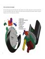
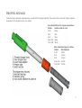
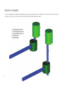
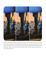
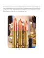
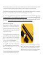
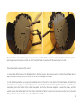
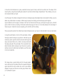
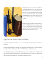
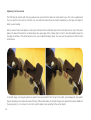
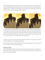
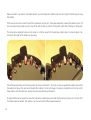
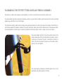
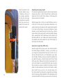
Mr.Bulletfeeder®
by Double-Alpha
User Manual
US Patent 74975155 and US Patents Pending
Thank you for choosing Mr.Bulletfeeder® by Double-Alpha!
This newly designed product will give you years of reliable service. It will make your reloading sessions easier and faster than
ever before!
It is critically important that you set up your bullet feeder correctly, so PLEASE take the time to read through this instruction
manual before starting to assemble and use your bullet feeder. You will save considerable time and effort by reading these
instructions first.
For further information, please visit our website www.mrbulletfeeder.com. There you can view detailed video tutorials on how
to set up and use your bullet feeder. If you have any questions, email us at [email protected].
WARNING:
Reloading ammunition is inherently hazardous. BE SAFETY CONSCIOUS AT ALL TIMES and ALWAYS USE EYE and
EAR PROTECTION. Maintain a sturdy, clean, organized reloading bench.
Contact Information
Double-Alpha Academy B.V.
Elzenweg 33b
5144MB Waalwijk, Netherlands
Tel: +31 416 660 464
fax: +31 416 392 040
Email: [email protected]
www.doublealpha.biz
www.mrbulletfeeder.com
Index
What’s In the Box, and Exploded View of Assemblies.......................1
Assembling and Adjusting the Powder Funnel.................................5
Assembling and Adjusting the Dropper...........................................8
Assembling and Adjusting the Collator Mounting System.................10
Adjusting the Nose Guide and Flip Ramp.......................................13
Assembling the Output Tube and Lead Spring Assembly..................17
Wiring Up.................................................................................19
What’s In the Box, and Exploded View of Assemblies
Inside the box you will find:
1. Collator Assembly
2. Dropper Assembly
3. Powder Funnel (for pistol calibers only)
4. Power Supply
5. Mount Assembly (dismantled)
6. Lead Spring Assembly
7. Instruction Manual
1
Collator Assembly
First remove the tape securing the collator plate in place and then turn the collator upside down to remove the collator plate.
You may need to shake it a little. Once removed, you can also remove the tape securing the spacers inside the nose guide.
Take care you do not lose these as they can fall out.
2
Dropper Assembly
Inside the square telescopic packaging tube you will find the dropper assembly, the powder funnel, and a set of spare stainless
steel balls for the dropper, as per your caliber.
Color identification for dropper assemblies:
Caliber
Switch cable-tie color
9/.38
Yellow
0.40
Red
0.45
Blue
5.56/.223 Black
7.62/.308 White
Size of ball-bearings per caliber:
Caliber
Ball diameter
9/.38
4.5mm
0.40
4.0mm
0.45
3.5mm
5.56/.223 6.0mm
7.62/.308 5.0mm
3
Mount Assembly
The mount assembly is shipped disassembled and you have to assemble it first. Included in the kit are the screws needed, as
well as a 4 mm hex key. You will also need a medium sized Phillips-head screwdriver.
4
Installing and Adjusting the Powder Funnel
Your Mr.Bulletfeeder® is supplied with a newly designed and improved powder funnel. The powder funnel is a very important
component of a bullet feeder of any kind, as it prepares the brass correctly so that the bullet can be seated in the case, and not
tip over as you index the shell plate. To achieve this, we have redesigned the powder funnel to allow for just the right amount
of expansion, without over flaring or stressing your brass.
It is recommended that you adjust your powder funnel first, before assembling the dropper, as you will need properly prepared
brass when adjusting the dropper.
Note that our droppers are somewhat shorter than the standard ones provided by Dillon, so you will most likely need to adjust
your powder measure die down. It is best to do this with an empty powder measure.
Place a resized brass under the powder measure, and cycle the handle of the machine down. Adjust the die of the powder
measure down in small steps until it makes full contact with the brass and is operated fully (charge bar slides forward and
backward).
Note how far the powder funnel tip enters into the brass before it is released. You should aim to adjust the funnel down until
the top edge of the case just starts to push up onto the tapered section of the powder funnel, achieving a minimum amount
of rim flare. In this position, the lower section of the powder funnel has entered into the case, expanding the top just a few
millimeters, enough to allow the bullet to sit correctly in the case and not tip over as the machine indexes.
A good test is manually to place a bullet into a case you have cycled through the powder station. With a well-adjusted powder
funnel, the bullet should be seated smoothly a couple of mm into the case, and should not fall out easily, even when you turn
it upside down.
5
The picture on the left shows a powder funnel not adjusted far enough down. The funnel enters into the case, but does not go
down far enough. The bullet may not be seated deeply enough, and may tip over as you index the machine. The center image
shows a correctly adjusted funnel – the case enters up far enough to just reach the chamfered area of the funnel and receive
a slight belling. The image on the right shows a funnel set too deep. The case is excessively belled and will fatigue quickly - it
may not hold the bullet straight.
6
The resulting bullet seating of the three powder funnel heights. The left bullet is not seated well, as the funnel is too high – and
as a result the bullet is likely to tip over as you index the machine. The middle bullet is well tapped into place, and will remain
straight and true as you index. The right bullet shows the result of belling the case too much. The deformation in the case will
cause rapid case fatigue, and the bullet may not remain straight as you seat it.
7
Installing and Adjusting the Dropper
For ease of handling, you can remove the top section of the dropper and use only the lower aluminum assembly. To do this,
open the small lock screw in the lower brass section of the dropper and gently remove the upper part of the assembly – from
the brass section up – and set it aside.
Since the dropper is generally installed in the station following the powder measure, place a properly prepared case in the shell
plate below that station, and cycle the press handle all the way down.
Note: If you are using a powder check in the station following the powder measure, you will need to install the bullet dropper
in the next station. On a 650, this means you will need to use a combined seating and crimp die in the final station.
Slowly screw the dropper’s threaded body into the tool head for 2 or 3 turns and then fill the dropper tube with bullets, all base
down. You can fit 5 or 6 bullets into that section.
Continue to screw the threaded body down until you see that the inner section stops moving down – it has made contact with
the rim of the case beneath it. Very slowly continue to screw the threaded body down until you hear and see the column of
bullets inside the tube drop down. Turn the threaded body another quarter turn, and tighten the nut by hand. This is the correct height position.
Raise the tool head.
You should see one bullet sitting firmly in the case. Note that the dropper does not seat the bullet to length and only lightly
taps the bullet in, so that it does not fall when the machine is indexed.
Do not over-tighten the locking nut! It is not necessary and you may damage the threaded body, which is made of aluminum.
Tighten by hand or lightly using a spanner/wrench. There is no force applied to the dropper body during function, so there is
no risk of it moving. If desired, a drop or two of low strength Loctite may be applied.
8
Do a final check by cycling the press a few times. Use your prepared case and 5 or 6 bullets in the tube for each cycle. Confirm
that each time one bullet is dropped and tapped into place on the case. Your dropper is now correctly adjusted.
Note that different brass may have slightly different lengths, even within the same caliber. Should you change your brass, you
may find you need to adjust both the powder funnel and the height of the dropper for best results.
Now assemble the top part of the dropper back into place, and tighten the lockup screw in the brass section. Make sure that
the dropper assembly is not rubbing up against any section of the powder measure. In some machines, these can be positioned
very close together. You may need to slightly rotate the powder measure a little, and/or rotate the retention spring in the dropper assembly. It is important that the dropper moves freely up and down, without any interference.
Dismantling the Dropper Body
Should you need to dismantle the dropper body, do
so above a bowl as the small steel ball-bearings inside fall out and are easily lost! Take care not to bend
the micro-switch arm out of shape. It must be free to
move in and out of the slot.
First remove the top section by unscrewing the lockup
screw in the brass section. Remove the top section
and set it aside. This part cannot be dismantled, and
should not need to be. You can clean it by running
through a cloth or a bore-rope type cleaner.
To dismantle the lower section, first remove the retention spring. Then the inner tube can slide down and
out of the threaded die body. As you push it down, the
three steel ball-bearings will fall out – be sure you are
over a bowl to catch them!
Three extra steel ball-bearings are included as spares.
You should not need to dismantle the dropper often.
The picture above shows the dismantled dropper lower section.
Once the clip is removed, the inner tube can be slid out downwards. Note the three small ball-bearings, which are caliber specific. Always dismantle over a bowl as the small balls will drop out
when you remove the inner tube from the threaded body.
9
In the inner tube you will notice two rows of three holes. The lower level is normally only used for very short bullets (perhaps
90 gr 9 mm or very short .40s). It is better to use the upper row of holes as it will allow the column of bullets to drop a little
further, thereby better tapping the lower bullet into place. (Rifle caliber tubes may have three rows of holes).
To reassemble, slide the inner tube into the threaded body from below until the row of holes is just visible. Position the three
steel balls on the same level of holes (each separated by 120 degrees) and slide it further up until the threaded body retains
the balls. Then slip the retention spring back into place. Use the upper groove when using the upper row of steel-ball pockets
(normal setup) and the lower groove when the steel balls are positioned lower for very short bullets.
Assembling and Adjusting the Collator Mounting System
The new Mr.Bulletfeeder® by Double-Alpha is designed to be attached to the outer rim of your case feeder. This improvement
makes the unit lighter and more compact, and takes no space at all on your reloading bench. The flexibility of this design
means that you can position your bullet feeder collator anywhere around the case feeder that best suits your need.
The symmetrical design of the new mount system enables you to mount the bullet feeder collator so that the case feeder is on
its left or its right. When mounting to a 1050, the case feeder will be to the left of the bullet feeder, and when mounting on a
650, to the right. The horizontal mount rods can be assembled protruding either left or right as needed.
10
The bullet feeder on the left is being prepared to mount to a 1050 (with the case feeder to the right of the bullet feeder). The
right image shows the setup for a 650, on which the bullet feeder is mounted with the case feeder to its left.
Follow these steps to assemble the mount:
1. Screw all the M8 screws into the threaded holes in the Delrin pucks. Two screws in each, for a total of eight. Take care to
align the screws correctly, and do not force them so as not to damage the threads.
2. First determine whether you are going to assemble the unit to the left or to the right of the bullet feeder, and attach the
horizontal rods accordingly. These horizontal rods have a pair of M4 threaded holes through them which line up with the corresponding holes in the bottom of the collator base-plate. Use the four M4 screws supplied. To access the screws, you first
need to remove the collator plate from the collator. Note that it is better to try and run the screws into the holes in the rods
first, just to clear any burrs which may make it difficult to assemble.
11
3. Once the horizontal bars are in place, assemble the lower pucks to them, and then the vertical rods. The design of this
mount system, using all-round profile parts, allows for an almost unlimited range of adjustments. This will allow you to position the bullet collator just right.
4. Set the angle. The collator is designed to function at a 45 degree angle. Small adjustments can be made from there, as some
bullets may collate better at a steeper or flatter angle. However, the starting point should always be 45 degrees.
A good method to set this angle is as follows: Push the front vertical rod all the way up through the upper puck, until both
pucks on that front rod are touching. On the back vertical allow a gap of 6.5cm (2.5-2.6 inches) between the inner edges of
those two pucks. Tighten the screws only lightly, just to hold the rods from sliding.
These puck positions will set the collator base at about 45 degrees when you hang it on the horizontal rim of your case feeder.
5. Hang the bullet feeder on the rim of the case feeder, rotating
the hanger parts into shape as you position it. Note that you will
most likely need to push the bottom horizontal rod through the
lower puck about half an inch, so that it can make contact with
the sloping side wall of the case feeder. This is important to stabilize the bullet collator and keep it level. Once all is in position,
carefully remove the bullet feeder and tighten up all the screws
in the mount assembly.
This image shows a good starting point for the angle adjustment, which will set the collator plate at the required 45 degree
angle. Note that the short vertical arm is set to zero distance
between the pucks, and the rear one has a gap of about 6.5cm
(2.5”) between the pucks.
12
6. Hang the collator back on the rim of your case feeder. Connect the output tube and spring to the top of your dropper and
make sure the collator is in the best possible position, allowing the most direct line for the bullets to feed down the output
spring. Make sure the spring is not pulling on the dropper. Once
you are satisfied with the bullet collator’s position, tighten the
screws on the inside of the upper pucks to lock the bullet collator in place.
Especially when mounting to a 650, you will want the lower horizontal rod to protrude through the lower puck as shown with the
red arrow, to rest up and support the collator’s weight, keeping
it level and preventing it from sagging outwards. The angled
side wall of the case feeder makes this necessary.
Adjusting the Nose Guide and Flip Ramp
The nose guide and flip ramp of the collator are the “business end” of the system, and they are what make the collator work
so efficiently.
Other bullet feeders utilize a rejection type system: when a bullet enters a pocket the wrong way up, it is rejected and has to
be inserted again. These systems are always rather slow on feeding bullets, and, in some cases, very slow.
Not so Mr.Bulletfeeder® by Double-Alpha! Mr.Bulletfeeder’s patented system has the ability to allow the bullets that are the
right way up to pass on down the tube, and those that are nose down, to be flipped in their pockets, so not wasting any time
feeding them down the tube base down. This is achieved by the nose guide and flip ramp.
13
Adjusting the Nose Guide
The first thing to consider with the nose guide is how many of the thin laser-cut insert plates to use. The unit is supplied with
four, two each 0.8 mm and 1.6 mm thick. You can add and remove these as needed, depending on the type and length of
bullet you are loading.
Add or remove these insert plates so that, when the head of the bullet falls down into the slot and rests on top of the insert
plates, the base of the bullet is not raised above the upper edge of the collator plate. In fact, it should be slightly below the
top edge at all times. If the bullet drops too low, use an additional spacer plate. You may need to experiment a little for best
performance.
In the left image, not enough spacers are used in the nose guide for this 124 gr 9 mm bullet, and consequently the bullet’s
base is dropping too low below the level of the top of the collator plate. In the right image, extra spacers have been added into
the nose guide (2 x 1.6 mm and 1 x 0.8 mm) and the bullet is now entering to the correct depth.
14
The second critical adjustment in the nose guide is to position it correctly so that the right amount of ledge shows inside the
pocket. This ledge allows bullets, which are base down, to ride over it and not fall into the groove in the nose guide, while allowing bullets which are nose down to fall in and be rotated. The amount of ledge you want really depends on the caliber and
profile of the bullets you are loading, and should be adjusted as needed.
The left image shows the nose guide positioned too low, too inwards, and so no ledge is showing. All the bullets, regardless
of their orientation, will drop into the slot and be turned. The middle image shows the correct amount of ledge showing in the
pocket. With this correct setting, the bullets which are base down will ride past the slot and not be rotated, while the bullets
which are nose down will fall in and rotate to the correct orientation. The image on the right shows the nose guide set too far
out – too much ledge showing – and so no bullets will fall in, and none will be rotated.
To adjust the nose guide, loosen the screw from below the collator base, and slide the nose guide inwards or outwards as
needed. Then tighten it up. You will need a Phillips-head screwdriver.
When you find the perfect position for a particular bullet type, make note of the nose guide position, and the number of spacers
in use, so the next time you can adjust directly to this setting.
Adjusting the Flip Ramp
Once a nose-down bullet has dropped into the slot in the nose guide, the rotating plate continues to move it clockwise, and it
begins to rotate past the vertical position in the nose guide before reaching and riding up the flip ramp to complete the 180
degree flip inside the collator plate pocket.
15
Make sure that it is up close to the collator plate if you are feeding short bullets such as 9 mm. Adjust it further away for long
rifle bullets.
If the ramp is set too far out and the tip of the bullet does not ride up it, it may slip underneath, causing the collator to jam. If it
is too close and a long bullet is used, it may lift the entire bullet up and out of the pocket, rather than rotating it in the pocket.
The ramp can be adjusted to move its tip closer to or further away from the spinning collator plate. You should adjust it according to the length of the bullets you are using.
The left image shows the correct ramp position for these 9 mm bullets – the ramp is close up against the collator plate and so
the bullets can ride up the ramp and complete their rotation. In the right image, the ramp is positioned much too far out for
these bullets, and the bullet tip is missing the ramp and jamming up beneath it.
To adjust the flip ramp, loosen the screw from below the collator base, and rotate the flip ramp’s tip closer to or further from
the collator plate as needed. Then tighten it up. You will need a Phillips-head screwdriver.
16
Assembling the Output Tube and Lead Spring Assembly
Now that your collator and dropper are well adjusted, it is time to connect the two and see the system work.
Your bullet feeder includes a lead spring assembly, which at one end has the collator output tube and at the other the spring
adaptor cap, which fits on top of the dropper.
First attach the collator output tube to the large hole positioned at about 2 o’clock in the base of the collator. Push it firmly in,
until it stops against the shoulder machined in the part. Rotate the output tube so that its debris slot is on the downward side,
thus allowing debris to fall through if necessary. Tighten the M4 screw lightly to hold it in place. Do not over tighten!
The spring adaptor cap fits on top of the switch section in the
dropper assembly, with its flat side facing the switch. There is
a set screw in the side of the part – screw that in to hold it in
place. The screw will enter into a groove in the switch section.
Again, do not over tighten!
The output tube is positioned so that the debris slot is on the
downward side, allowing debris to fall out.
17
Note the position of the
spring’s adaptor cap as
it attaches to the top of
the dropper assembly.
Its flat side fits snugly
around the micro switch.
Note the two wires attached to the outer terminals of the switch.
18
Adjusting the Spring Length
The spring is supplied long enough to suit the most extreme
case we have found – that of the old 650XL, with the case
feeder set off to the left of the machine. In that setup, the
spring needs to be full length.
With the newer 650, or 1050, you may find that you can cut
a little off from the spring to get better performance. You
need the spring to reach down to the dropper without pulling
on it at all, as that tension can cause the dropper to snag.
However, you don’t want the spring to be too long – that can
cause a bend in the spring which could trap bullets midway
down, causing them not to slide down as they should. Find
the best position for your collator which allows the straightest possible route down towards the top of the dropper, so
the bullets can slide easily.
Special note regarding 1050 setup
Here the length of the spring is even more critical! Since the
tool-head (dropper assembly) is moving up and down as
you reload, the spring should not be cut too short. You do
not want the spring to pull up on the dropper as you lower
the tool head. Therefore, when you position the collator unit
and adjust the spring, check the length with the tool-head
all the way down. Make sure the spring is long enough not to
pull on the dropper. You may then find that, when you bring
the tool-head up, a bend is created in the spring, but if the
collator is well positioned, this should not become a bullet
trap. Check this as you set up. You can also make a further improvement by improvising a supporting loop midway
down the spring, perhaps attached to the case feeder, which
prevents the bend from being too pronounced in the spring.
Wiring Up
The power supply provided with your unit is dual voltage, and includes a choice of
two mains cables: one for the US market (110v) and one for Europe (220v). Select
and attach the correct one for your region.
The 12v DC cable is long enough to allow you to position the power supply in an
accessible position on your reloading bench. Plug that connector snugly into the
female jack protruding from the side of the collator base.
The micro switch on the dropper serves to stop the collator from turning and feeding
bullets when the dropper tube is full. Since the bullet feeder can collate bullets much
faster than you can use them, it is necessary to have this cut off switch to prevent
the bullets filling up the lead spring all the way to the collator and jamming it.
Attach the two terminals at the end of the retractable cord to the two outside terminals of the micro switch, and push firmly into place. The middle terminal on the
switch is not used, and is bent down to avoid confusion. There is no polarity to be
concerned with: either wire can be attached to either terminal.
Your unit is now ready to run.
The power supply provides an adjustable potentiometer switch, which allows you to
supply the default full 12v power that will provide maximum speed. You may find
that some bullets collate better at a slightly slower speed, and you can run the collator on 9v or less as well.
CAUTION: Should the collator stall for any reason, be sure to turn the power off before trying to clear it. It can be dangerous if it suddenly starts turning while your fingers are close to the collator plate. The plate turns with
considerable force!
Connect the end terminals of
the retractable cable to the
two terminals of the micro
switch, as shown. The middle
terminal is bent down and is
not used. There is no polarity
to be concerned with.
19


![3URIHVVLRQDO HTXDOL]HU [ EDQG](http://vs1.manualzilla.com/store/data/006777932_1-770431aef94eb6d0b1e65f32ec91758b-150x150.png)