1
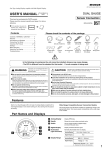
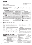
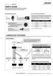
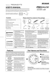
Tacho Meter
(PT1/PT2 As of December, 2008 No.2)
PROGAUGE
USER'S GUIDE
Thank you for purchasing PIVOT “PROGAUGE”. Please read these instructions carefully before
installing or using this device. Please do not lose this user’s guide, as you will held liable for the
cost of reissuing it.
Please check the contents of the package.
Common accessories for PT1 and PT2
Meter
Adjustable
Stand
Double-sided
Tape 2
CAUTION
Allen
Wrench
Cushion
Tape
Cut Connectors
3
Improper use or disregard of these warnings
may result in the injury or death of people.
● Do not work in areas where there
is excessive exhaust
Due to vehicle exhaust emission poisoning
or fire may result in a damage to humans.
● Please
for PT1
securely fasten
product to a stable place
the
It is very dangerous if, while in use, the
product falls off and interferes with braking.
● Do not crush the cable
User’s Guide,
ECU Wiring
Diagram List
5-pin
Coupler Cable
● Do not use electrotape
● Do not operate while driving
yourself, please consult your local pro shop or garage
When installing this product, we recommend that if technical
knowledge becomes necessary please consult a qualified mechanic.
● Do not install the product in any place subject to
high temperature or any place where water may be
splashed
● This product is for DC12V cars;
● During installation be sure to
remove the – cable from the
battery
● Please be sure to store bundle away
So as to prevent fire and damage resulting
from the shorting of circuits, etc…
It is very dangerous to pull tangled wires by force
or allow tangled wires to interfere with driving.
installation cannot be carried out on cars
with other voltage batteries.
● Make sure to replace all screws and parts to their
● Just after installation do not exert
● Do not install the product in a place where it will
all wires with tape, etc…
any strong force on the product
original place
cause distraction
When double-sided tape is used for an
installation be warned that when hot the
tape temporarily losses adhesiveness.
● Do not, in any manner, process, take apart, or
make changes to this product
FEATURES
Auto-Peak display
World's First Auto-Peak Display provides Accurate Peak Numbers
with each and every Shift.
By setting to "Auto-Peak" Mode the reading will be held for one second
whenever revolutions exceed the set shift point; making it easy to see when
an over-rev has occurred. It is also possible to set the optimum shift point so
as never to enter the red zone. (patent pending)
World’s First
AUTO PEAK
3 Types of
Display
All-in-One
Unit
Male Wire Crimps
with Cover 3
● If you are not confident about doing the wiring
Wiring should be carried out using the
attached "cut connector" or by soldering,
make sure to securely insulate all wiring
parts with insulation tape, and confirm that
no wires are sticking out.
Operating or checking the display during driving
may cause an accident; please use with the
utmost consideration for safety.
5-pin Connector with
OBD2 Connector
Improper use or disregard of these warnings may cause injury to
persons, damage the product and / or other things.
NOTE
Please be careful that the cable does not get
crushed by the seat rail or car door steel plate, nor
cut by any sharp steel plate as this may cause a
poor connection or an electric short leading to fire
or other danger.
for PT2
Holding peak for one
second upon exceeding
set shift point.
Three types of display;
Real / Auto-Peak / Peak.
No separate controller
necessary.
No Wiring
Coupler On
(Only PT2)
1600 rpm
(rpm)
8000
OVER
A
OVER
OVER
(rpm)
8000
7000
6000
4000
2
4
6
8
Fastening with double-sided
tape means no need for opening
holes.
10
12
14
16
18
Cylinder
&
With some Toyota and Daihatsu
models it is possible to connect
directly using the coupler to the
diagnostic monitoring connector.
(S)
Red Zone
Shift Change
(1S)
Part A
All 1~8 cylinder
compatible.
cars
Compatible with wide range
World's
Lightest
Body
Extra lightweight means
less vibration; only 107
grams (unit only).
Translucent
Illumination
The translucent LED
system provides a clear
even display.
gives you warning lights as you
approach the set rpm.
Opening
Holes
800 rpm
Red Zone
6000 Shift Change
The sequential lamp system
No need for
1200 rpm
ADVICE
FUNCTION
Some Tips for Setting the Shift Point!
Three Types of Display
For Sports Driving
Three Types of Display: Real-time, Auto-peak and Peak hold.
REAL
Normal Real Display for All Areas.
AU T O
PEAK
Below the shift point=Real Display
The shift point should be calculated by subtracting the over-rev at shifting from the
rpm at which the maximum engine torque occurs.
Above the shift point=After holding the peak reading for one second, the
real time display allows you to check for over-revs.
The over-rev at shifting should be decided by actually measuring in Auto-peak mode.
In general it would be about 90% near the red-zone.(EX: If the red zone is 9,000 rpm, then use
8,000 rpm.)
For Eco-driving
When using for eco-driving, it is best to use a lower rpm point as the shift point, so set
the point at 1000 rpm higher than normal and shift when the green lamp comes on.
NOTE : The above is for your reference only; please make settings as desired.
PART NAMES AND FUNCTIONS
RPM beyond the Shift Point
PEAK
One-second Peak Display
Return to Real display
Shows the peak reading after the engine begins running
1 Switch
Use to change modes and/or settings.
2 Shift Lamp (LED)
Shift Lamp
2
Blinks at the set rpm.
(Setting Range : 3000 - 10000rpm, 200rpm unit)
In order to prevent over-revving while shifting, an F-1 sequential type shift has
been included, which shows a green lamp 1000 rpm before the set engine rpm
and a red lamp at the shift point.
Normal
1000rpm before
Shift Point
3 Needle
Show the current values.
5
4 Illumination (night illumination)
Normally illuminated when on display.
1
3
(Not illuminated when only parking lights are on.)
5 Wide Range Display
All Lamps OFF
The lamp in the middle
lights up in green.
The lamps to the left and
right blink red.
The display has been made easier to read
by enlarging the 3,000 to 8,000 rpm area.
1
CONNECTING THE WIRES
Preparation
PT1
Before installation, please check that the installation method is proper for the model of car.
Basic Wiring
12V with key switch ON
Key Switch
ON
Engine Computer
Engine Revolution Signal
CAUTION
TA
RED = I G N (12V with key switch ON)
Backside
When another device is already connected
to the revolution signal from the ECU .
WHITE = Signal (Engine Revolution Signal)
and that device works properly keep that
wiring.
BLACK = G N D
5-pin Coupler
Earth
and the Meter or other device stops working
properly or sometimes becomes unstable
disconnect from the ECU wire and get the
terminal of
revolution signal from the
ignition coil or diagnosis.
ORANGE = I L M (12V with parking lights ON)
Normally this wiring is not necessary.
Parking lights
This wiring is to use the lowest brightness for
the shift lamp when only the parking lights are
on; hence neither the dial or the needle will be lit
up when running with parking lights on.
= Use Cut Connector (or Solder)
Parking Lights ON
(Vehicle Side) 12V
To get revolution signal from ignition coil use resistor wire included in kit.
To get revolution signal from Diagnosis
(check connector)
Location of
Revolution Signal(IG
Ex : In case of
MAZDA EUNOS ROADSTER
(NA6)
CAUTION
To get revolution signal
from Ignition Coil
)
When connecting the revolution signal to the
ignition coil or diagnosis and the indicated
rpm on the meter may be obviously lower
than the actual rpm as shown on tachometer.
WHITE Wire
To Meter
Ex: For a 6 cylinder car, the reading should be
3,000rpm, but display shows 500rpm.
This may be caused by the individual wiring
system of that model of car. Change the Cylinder
Setting to "1". See "SETTINGS A" for details.
WHITE Wire
Ignition Coil
To Meter
PT2
When used in conjunction with other PIVOT Diagnostic Monitor
Connected Products.
Not compatible with another company's products
Basic Wiring
Connect the OBD2 Connector.
Insert while the engine is running.
In order to prevent making mistakes when inserting the coupler, make sure to
insert while the engine is running.
Connector
on the Car
If you wish to install the PT2 and another device which
connects to the diagnostic monitoring connector it is
only possible if your car model type is compatible with
both devices.
Connect to the Diagnostic
Monitor Connector.
For details about the
connector position, see
the "RPM Signal Wiring
List" (separate sheet).
Backside
5-pin Coupler
Diagnostic
ORANGE = ILM (12V with parking lights ON)
Normally this wiring is not necessary.
= Use Cut Connector (or Solder)
GREEN= Monitor Signal
WHITE
RED
RED
X3,RM-07
WTM
and others
RED BLACK WHITE
Parking Lights
Parking Lights ON
(Vehicle Side) 12V
PIVOT product
connected to the
Diagnostic Monitor
Connector
BLACK
BLACK
Power
Source
Earth
Revolution
Signal
Backside
This wiring is to use the lowest brightness for the
shift lamp when only the parking lights are on;
hence neither the dial or the needle will be lit up
when running with parking lights on.
Remove the red and green
insulation caps and insert the
male connector.
5-pin Coupler
=Connect(Wire Crimps)
How to process the OBD2 Connector to use with other PIVOT Products.(X3.RM-07.WTM)
10cm
5cm
1.Disconnect the OBD2 Connector.
2.Cut at about 10cm from the connector.
Cut
Sheath
3.Remove about 5cm of sheath from where it
has been cut.
4.Leaving the black, white and red wires, cut off
wires and securely insulate with insulation
tape.
Insulation Tape
.
.
Black White Red Wires
5.Properly connect the black, white and red
wires using a connector. (See [ Reference
1]How to use the Connectors.)
Connect(Wire Crimps)
[Reference 1] How to use the Connectors.
How to use the Cut Connectors.
1
3
Peel off about
10mm of the vinyl
cover at connection.
2
Peel off about
10mm of the vinyl
cover at the end of
the product’s wire.
4
How to use the Male Wire Crimps.
Twist the
uncovered
wires.
Close tightly
with cut
connector.
Use a crushing tool to press the
cut connector, if you do not
have such a tool, use pliers or
such to fold and crush the
connector together for a secure
contact.
After covering, make sure to
insulate properly with vinyl tape.
1
5
Peel off about
10mm of vinyl
covering from the
tip of the wire.
Crush the center
tabs of the crimp
down to hold the
center of the wire.
2
6
Bend the outside
wires around the
core to make the
wire thicker.
Crush down the
outer tab of the
crimp over the
vinyl covering.
3
Pull the wire
through the cover.
4
Place the wire
onto the crimp.
Securely connect the male
and female crimps, making
sure to twist the male cover
firmly into the female cover.
Notes about using the OBD2 Connector.
If you unable to get a grip
on the distended portions.
CAUTION
With some car models it may be difficult
to get a good grip on the connector.
Make sure to grip the
distended portions when
pulling it out or inserting it.
2
In such cases, use
a lock tie to push or
pull the connector.
Do not pull on the wires
when trying to remove the
connector; the wires may
become disconnected.
BASIC OPERATIONS
1
2
ENGINE
START
Basic Operations from Engine Start to Stopping.
Opening
Demo
3
Start the engine.
Preparation
A
ENGINE
START
3
While holding down the switch, start
the engine.
5
6
(The factory default setting is for a
four-cylinder engine.)
Press the
switch once
Press the switch to change the
pattern and set to the proper one.
8
=Blink
Special A
1
2
Press the switch
for 1.5 seconds
While the tachometer is being
displayed, press the switch for
longer than 1.5 seconds.
2
4
5
With no operation
for 2 seconds
Tachometer Display
The needle will show the set
shift point.
The lamps blink red.
3
Each pressing of the
switch will raise the
setting 200 RPM; at
10,000 RPM it will
return to 3,000 RPM.
Press the
switch
Number of
cylinders
Shift Lamp
1
= ON
= Blink
=OFF
While holding down the switch,
change the RPM setting.
Car Models
NISSAN(FAIRLADY Z Z33).MAZDA(ATENZA and others)
MAZDA(RX-8).SUBARU(PLEO and others)
1
1
2
Meter
OFF
Press for 1.5 seconds
3
Patterns for Cylinder Settings Display.
0
=OFF
Shift Point Setting
1
Cylinder Display
4
Opening Demo
4-cylinder
2
Make RPM setting for turning on the Shift Lamp.(Setting Range = 3000-10000rpm)
Set the cylinder number for the car being used.
The number of cylinders is set by the shift lamp pattern.
Turn
6
Engine
Stop
OFF
Due to characteristics of
the gauge, even though the
engine is OFF and the
gauge is not measuring, the
needle will not return to "0".
=ON
D
Cylinder Number Setting
2
5
After finishing the installation, make various settings.
Please check the number of cylinders and cycles for the
model car being used.
1
Current
RPM
Display.
Shift Lamp will light up at night.
It will not operate properly
unless the wiring to the RPM
signal has been completed.
SETTINGS
4
The needle
will show the
set shift point.
By continually pressing down on the
switch the needle will move to 10,000 RPM.
1
For one and two cylinder engines, set the signal level switch to two.
E
Shift Lamp Brightness Setting
Press for 3 seconds
See "F How to Switch the Signal Level" for details.
3
4
5
6
8
Make settings to change the Shift Lamp brightness.
Three-cylinder
(With parking lights ON, brightness is fixed at the lowest possible.)
Four-cylinder. Rotary Engine(RX-7)
Five-cylinder
1
Six-cylinder
Eight-cylinder
Special A
5
While the tachometer is being
displayed, press the switch for long.
NISSAN MARCH/CUBE, Cars equipped with an HR-type Engine.
Reference : If the engine is a two cycle engine, multiply the number of cylinders by two.
(EX:For a two-cycle three-cylinder engine the setting would be six.)
Press the switch
for 3 seconds
2
With no operation
for 2 seconds
4
5
With no operation
for 2 seconds
Tachometer Display
After 1.5 seconds the shift
point will be shown and after 3
seconds.
all shift lamps will light.
6
Tachometer Display
3
Bright
5 steps
Dark
Press the
switch
B
Switching the Display (Auto-peak / Real-time)
While holding down the switch,
change the brightness setting.
Press
Each pressing will decrease the
brightness; when pressed at the darkest
setting it will return to the brightest
possible setting.
Switching the Auto-peak / Real-time Display.
1
Press the
switch once
While the tachometer is being
displayed, press the switch once.
2
3
Peak Display
4
5
With no operation
for 2 seconds
Tachometer Display
Shift Lamp ON
(Setting)
Press the
switch
Pressing the switch changes the
peak reading display mode.
F
Switching the Signal Level
Press for 5 seconds
Changes are only necessary for those car models listed below.
NISSAN FAIRLADY Z Z33) . MAZDA(after 2002) . SUBARU(PLEO and others)
. MITSUBISHI(COLT and others)
See [ECU Wiring Diagram List] How to use the Connectors.
Auto-peak
1
Real-time
2
PEAK AUTO REAL
ON
Key ON
(Engine Stop)
Press the switch
for 5 seconds
5
With no operation
for 2 seconds
6
Lamp Off
1=If the generic car.
2=If the level is small.
PEAK AUTO REAL
3
C
Peak Display and Re-set.
4
Peak display and Re-set.
1
Press the
switch once
3
Peak Reading Display
Press the switch
for 2 seconds
Press the
switch
Set the signal detection level by
pressing the switch to change the
needle position to the correct setting.
Pressing the switch will re-set the
peak reading.
While the tachometer is being
displayed, press the switch once.
2
The lamps blink red.
Press
4
Tachometer Display
3
METER INSTALLATION
A
Install in an easy-to-view location.
Installation with the Adjustable Stand
Cushion Tape
Doublesided Tape
Hexagonal Bolt
with Washer
Fasten using the
double-sided tape.
(On top of the steering column cover or
dashboard.)
B Installation with the
When using the provided Band Holder to install on the dashboard.
Holder
Band
1. Installing the Adjustable Stand
1 Place the stand’s holder band around
the back of the meter.
NOTE : If you cannot get the band
around the meter, loosen the hexagonal
bolt and expand the band.
2 After getting the band in place, tighten
the hexagonal bolt to secure the band.
Hexagonal
Bolt
Clean to remove
oil & dust
2. Installing to the Car
1 Bend the stand to securely fit the place of
installation.
2 Clean the surface; removing all oil or dust.
3 Fasten using the double-sided tape.
Please be sure about where you wish to install the
meter, as it is not advisable to reuse double-sided tape.
Can be Mounted in Various Places
Meter Dimensions
Mount almost anywhere using the doublesided tape. After mounting it is possible to
adjust the face of gauge
for easy-reading.
(unit : mm)
ø80
103
on the steering
column cover
Panel
Wrap the cushion tape
around the base of the
meter and forcibly inser t
into the 80mm hole in the
panel.
A Pillar
Screw Hole
Pillar
Holder
Pillar Holder for ø80
PH-80 1,780
56
BASIC FLOW OF OPERATIONS
Cushion Tape
If you wish to open
holes to fasten the unit to
the pillar or column cover,
please purchase and use
the separately sold pillar
holder.
17.5 23.5
ø92
on the
dashboard
After deciding the
position and angle of
the meter face, fasten
the hexagonal bolts on
both sides to secure.
4
Basic Flow of Operations for PROGAUGE. For details about settings see each [SETTINGS].
With engines stopped
Press
switch
While holding down the
switch, start the engine.
Engine Start
Long Press
of switch
Opening Demo
Changes
automatically
Operate
Switch
Opening Demo
Setting
Shift Point Display
No
operation
A
Cylinder Number
Setting
Engine Revolution Display (Auto-peak/Real-time)
Press the switch
for 1.5 seconds
Press the
switch
Setting
B
Switching the Display
Auto-peak/Real-time
Setting
C
Setting
Peak display
and Re-set
D
Press the switch
for 3 seconds
Setting
Shift Point
Setting
E
Shift Lamp
Brightness Setting
With no operation
for 2 seconds
Demo Mode Settings and Deletion.
Demo-mode is used in stores to show and explain operations; for most Users it is not necessary.
Demo Mode Settings
1
ON
Key ON
(Engine Stop)
Demo Mode Deletion
2
Press the switch
for 10 seconds
3
1
Demo
Operations
Press the switch
for 5 seconds
2
Demo-Mode
Deletion
TROUBLESHOOTING
Trouble
The opening demo does not work.
Possible Causes
The engine does not start.
Possible Solutions
Start the engine.
Poor connection of each wire.(It will not operate properly Check the coupler connections or conditions.
unless the wiring to the RPM signal has been completed.)
Engine is running but tachometer doesn't
work.
The car's tachometer and PROGAUGE
readings are very different.
Poor connection of each wire.
Check the coupler connections or conditions.
Poor connection of 5-pin coupler cable or OBD2 connector.
Check the coupler connections or conditions.
The signal detection level is not correct.
See page 3 [SETTINGS F] and [ECU Wiring Diagram List], make any
necessary changes.
The cylinder setting is wrong.
Due to differences in accuracy, readings may not be the same as those on
the standard tachometer.
See page 3 [SETTINGS A] and make any necessary changes.
The signal detection level is not correct.
See page 3 [SETTINGS F] and make any necessary changes.
The Shift Lamp does not light up.
The engine rpm has not reached the set shift point.
See page 3 [SETTINGS D] and make any necessary changes in the rpm shift point.
Even with the parking lights on, brightness
of the shift lamp does not decrease.
Contact failure of ORANGE wire (parking lights ON + 12V).
Check the Orange wire connections or conditions.
The gauge is operating even when the
engine had been stopped.
Noise from the car (door locks and so on) may cause it to If the operation is only temporary it is not a malfunction; but if it still causes
worry cut the red wire in the OBD2 connector and connect it to IGN.
temporarily operate.
With the key OFF, the needle does not rest on "0".
This is a special characteristic of the meter's movement and is not a malfunction.
The auto- power window function and/or
other electronic devices are re-set.
This is due to the minus terminal on the battery being Re-connect the minus terminal and follow re-setting instructions for any
affected devices.
disconnected.
4
PIVOT CORPORATION
87-3, Shimookada Okada, Matsumoto-shi, Nagano, 390-0313 Japan
TEL0263-46-5901
http ://pivotjp.com/