1
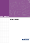
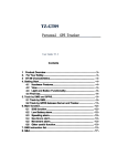
Website: www.ChinaGpsTracking.com
GPS
Vehicle
Tracker
User Manual
AVL-100
version 1.6
Website: www.ChinaGpsTracking.com
Document Review
Name of document
AVL-100 user manual
Version number
V1.6
Made by
UVI Hi-tech Corporation
Edited by
Kevin Chu
Issuing date
2011‐10‐29
\
Email: [email protected]
[email protected]
Mobile: +86 186 7550 6905 (English only)
Contents
1. Product Overview ........................................................................................................................................... 4
2. For Your Safety............................................................................................................................................... 4
3. AVL-100 Characteristics ................................................................................................................................ 5
4. Getting Started ............................................................................................................................................... 6
4.1 Hardware and Accessories .......................................................................................................... 6
4.2 Outside feature .............................................................................................................................. 6
4.3 IO socket feature ........................................................................................................................... 7
4.4 Connecting and Installation ......................................................................................................... 8
5. Change Password .......................................................................................................................................... 8
6. Track ................................................................................................................................................................ 8
6.1 Track by SMS ................................................................................................................................. 8
6.2 Track by Calling ............................................................................................................................. 9
6.3 Track by Preset Interval ................................................................................................................ 9
6.4 Track by fixed miles Interval ........................................................................................................ 9
6.5 Google Earth and Google Map ................................................................................................... 10
7. Authorization ................................................................................................................................................ 10
8. Application Examples for Inputs. ................................................................................................................ 11
8.1 Detecting Lock Status of Car’s Door or Trunk (Car Boot). ...................................................... 11
8.2 Ignition Detection ......................................................................................................................... 11
8.3 Analog Input.................................................................................................................................. 11
9. Low Battery Alarm ....................................................................................................................................... 12
10. Over speed .................................................................................................................................................. 12
11. Geo-fence .................................................................................................................................................... 12
11.1 Geo-fence Alarm ........................................................................................................................ 12
12. Output Control ............................................................................................................................................ 13
12.1 Output Control (Unlimited) ....................................................................................................... 13
12.2 Output Control (Limited)........................................................................................................... 13
12.3 Application Examples for Outputs .......................................................................................... 13
12.3.1 Engine Cut.............................................................................................................................................. 13
13. SMS/GPRS instruction............................................................................................................................... 14
-2-
-
\
Email: [email protected]
[email protected]
Mobile: +86 186 7550 6905 (English only)
-2-
1. Product Overview
AVL-100 is a GPS/GPRS based tracking device specially developed and designed for vehicle real-time tracking
and fleet management.
AVL-100 has inbuilt GPS module to obtain accurate position data and utilizes its GSM capability to send the
position data to a specified mobile phone or server base for tracking and fleet management.
With internal memory, AVL-100 can store GPS coordinates when there is no GPRS connection or at a specified
interval requested by the user.
One optional feature of AVL-100 is that a microphone can be linked out to be hidden somewhere inside the
vehicle for listening to the cabin.
AVL-100 has the following functions and features:
› SMS and GPRS TCP/UDP Communication
› Track on Demand
› Show Location Directly on Mobile Phone
› Track by Time Interval
› Listen (Voice Wiretapping) (Optional)
› GSM Blind Area Memory
› Logging Capacity up to 180,000 Waypoints
› Inbuilt Motion Sensor for Power Saving
› SOS Panic Button
› Geo-fencing Control
› Low Battery Alarm
› Speeding Alarm
› Power-cut Alarm
› Engine Cut (Stop Engine)
› I/O: 1 switch inputs, 2 digital inputs, 1 digital output, 1 analog input.
2. For Your Safety
Read these simple guidelines. Not following them may be dangerous or illegal.
Proper Connection
When connecting with other device, read carefully its manual so as to
carry out correct installation. Do not connect it to other incompatible
devices.
Qualified Accessories
Use original parts, qualified batteries and peripheral equipments to
avoid damage to AVL-100.
Safe Driving
Drivers should not operate this product while driving.
-3-
Qualified Service
Only qualified personnel can install or repair AVL-100.
Water Resistance
AVL-100 is not water resistant. Keep it dry. Install it inside the vehicle or
use waterproof bag if necessary.
For safety reason, do not tell other people the mobile phone number of
Confidential Phone Number
your AVL-100 without taking precautions of security settings.
3. AVL-100 Characteristics
Items
Specification
Power Supply
+12V - +24V / 1.5A
Backup Battery
850mAh
Normal power consumption
85mA/h
Dimension
70*76*28mm
Weight
140g
Operating temperature
-20°to 80°C
Humidity
5% to 95% Non-condensing
Frequency
Quad Band GSM 850/900/1800/1900Mhz
GPS Module
latest GPS SIRF-Star III chipset
GPS Sensitivity
-158Db
GPS Frequency
L1, 1575.42 MHz
C/A Code
1.023 MHz chip rate
Channels
20 channel all-in-view tracking
Position Accuracy
10 meters, 2D RMS
Velocity Accuracy
0.1 m/s
Time Accuracy
1 us synchronized to GPS time
Default datum
WGS-84
Reacquisition
0.1 sec., average
Hot start
1 sec., average
Warm start
38 sec., average
Cold start
42 sec., average
Altitude Limit
18,000 meters (60,000 feet) max.
Velocity Limit
515 meters/second (1000 knots) max.
LED
3 LED lights to show GPS/GSM/Power status.
Flash Memory
32MB
Button
One SOS Button
Interface
1 switch inputs, 2 digital inputs , 1 digital output,1 analog input
-4-
4. Getting Started
This section will describe how to set up your AVL-100.
4.1 Hardware and Accessories
AVL-100 is supplied in a box which includes:
AVL-100 with Battery
GPS Antenna
GSM Antenna
Wires with SOS Button
Configuration
Cable
CD-Rom
4.2 Outside feature
GPS LED (Blue LED)
light 0.1s dark 2.9s
GPS Signal Well
light 1s dark 2s
No GPS signal
light 0.5s dark 0.5s
GPS Fault
Tremble/Power LED (Red LED)
light 0.1s dark 0.1s
System Initial
light 1s dark 2s
Low Power
light 0.1s dark 2.9s
Power Good
always light
On Tremble
GSM LED (Green LED)
light 0.1s dark 0.1s
System Initial
light 0.1s dark 2.9s
GSM Signal Well
light 1s dark 2s
No GSM Signal
always dark
No SIM Card Or Bad SIM Card
light 0.1s dark 0.1s (flash three times)
Call Ring
always light
In A Call
light 0.1s dark 0.3s (flash five times)
Send A SMS
-5-
SOS Button
SOS button is connected with the wires. Press it to send SOS alarm to
preauthorized phone number.
Configuration cable
Used for firmware update, configuration TT500 on PC (configuration which in the CD is
required.)
SIM Card Holder
To insert SIM card here
GSM Antenna
Connector for GSM antenna
GPS Antenna
Connector for GPS antenna
Microphone
A microphone to be linked out for listening to the cabin (wiretapping)
Power On/Off Button
Press and hold for 3~5 seconds to turn on/off TT500.
4.3 IO socket feature
DC Characteristics of PINs
PIN
Inactive
Active
Maximum
Digital input 1
(PIN5)
Open drain or >1V
0V(GND)
45V
Digital input 2
(PIN3)
Open drain or 0V(GND)
>3V
45V
Digital output A/B (PIN4/2)
Open drain
0V (GND)
45V/500mA
Analog input
/
0~6V
30V
/
12-24V
45V
(PIN1)
DC IN (PIN7+PIN8)
Application of PINs
PIN
Alarm
Pin 1
type
Application
/
Fuel sensor
Description
Analog Input to detect the voltage; always use to detect the fuel in the tank.
Instruction Reference: *$$$$$$,008,ABCDEFG#, *$$$$$$,113,A,B#
Pin 2
/
Cut circuit
Connect with a relay to cut current circuit;
Instruction Reference: *$$$$$$,025,B,Y#
Pin 3
0x52
Door status
0x53
Pin 4
/
Once this Pin3 was triggered by high voltage or it drops to low level, tracker will send a GPRS alarm to your
preset server. Alarm type for it is: 52/53; Always used to detect door status.
Cut engine
Connect with a relay to cut current circuit;
Instruction Reference: *$$$$$$,025,A,Y#
Pin 5
0x50
Engine status
The function is the same as I/O 3, but the alarm type is “50”, “51”. Use to Detect status of the engine;
0x51
Pin 6
0x01
SOS
When SOS Button cable is connected to GND(port 08), namely trigger, the unit will send out a data via SMS or
GPRS, alarm type is “01”
Pin 7
/
Pin 8
/
Positive (+12v)
GND
The anode of power input socket (12V~24v);
GND, the cathode of power input socket;
-6-
4.4 Connecting and Installation
Read this manual before using your AVL-100 and check if all parts are included in the packaging box.
4.4.1 Ensure that your AVL-100 has a working SIM installed.
- Check that the SIM hasn’t run out of credit (test the SIM in a phone to make sure it can send and receive SMS)
- Check that the SIM Lock code is turned off
- If you require the function of sending an SMS location report to the authorized phone number when it makes a
call to the AVL-100, please make sure the SIM installed supports displaying caller ID.
4.4.2 Antenna Connection
Connect the GSM Antenna to AVL-100.
Connect the GPS Antenna to AVL-100.
- GPS antenna is used to receive satellite signals in the sky. It should be fixed to face the sky (to be placed under the
windscreen is recommended) and should not be covered or shielded by any objects containing metal.
4.4.3 Find a suitable place inside the car for installing AVL-100. Wiring connections must be firm and reliable and
the joints should be wrapped with insulating tape tightly. The unused electrical wire should be properly insulated.
Check if all wirings have been connected correctly and then connect the AVL unit to the motor power.
Check that the Red LED (Battery) is flashing light 0.1s and dark 2.9s.
Make a missed phone call the AVL-100 using a mobile phone to check if the calling can go through and the AVL-100
replies with an SMS indicating longitude, latitude, speed and date.
5. Change Password
Command: *$$$$$$,001,@@@@@@#
Description: Change user’s password.
Note:
1. $$$$$$ is user’s password and the default password is 000000. The tracker will only accept commands
from a user with the correct password. Commands with wrong password will be ignored.
2. @@@@@@is the new password. Password should be 6 digits.
Example:
*$$$$$$,001,@@@@@@#
*000000,001,123456#
The password will change to 123456.
6. Track
6.1 Track by SMS
- Track on Demand - Reply with longitude, latitude, speed and date
Command: *$$$$$$,000#
Description: Get the current location of the tracker, send this SMS or make a telephone call directly to the
tracker and it will report its longitude and latitude by SMS with format as follows:Lat:+2232.5742N Long:+11403.3990E Spd:000km/h Fix:A Sat:04 HDOP:02.6 GSM:12 Batt:04.18V
Mile:0.0564 Time:11/07/11 09:59:29
-7-
Example:
*$$$$$$,000#
*000000,000#
Tracker will send the current position to your mobile by SMS.
- Track on Demand - Reply with a Google link
Command: *$$$$$$,100#
Description: Send this command to the tracker and then you receive an SMS with an http link. Click on the
link then the location can be shown directly on Google Map on your mobile phone. For example:
http://maps.google.com/maps?f=q&hl=en&q=22.539145,114.063590&ie=UTF8&z=16&iwloc=addr&om=1
Note: Only smart phones and PDA support this function.
Example:
*$$$$$$,100#
*000000,100#
6.2 Track by Calling
Make a missed call to the tracker and it will report its longitude and latitude by SMS with format as follows:Lat:+2232.5742N Long:+11403.3990E Spd:000km/h Fix:A Sat:04 HDOP:02.6 GSM:12 Batt:04.18V
Mile:0.0564 Time:11/07/11 09:59:29
6.3 Track by Preset Interval
Command: *$$$$$$,002,X,Y#
Description: Set an interval for the tracker to continuously return its location by SMS
Note:
1. X is the interval in minute. If XXX=000 to turn off tracking by time
2. Y is the amount of SMS which are going to send to your mobile. If Y=999, tracker will send SMS continuously.
Example:
*$$$$$$,002,X,Y#
*000000,002,5,999#
The tracker will send location data back to your mobile phone every 30 minutes;
6.4 Track by fixed miles Interval
Command: *$$$$$$,121,X,Y#
Description: send the GPRS by fixed time interval;
X=0 disable this function, X=1 enable this function;
Y= [0, 60000]/meter The value of the distance can be set.
Example:
*$$$$$$,121,X,Y#
#000000,121,1,50#
The tracker will send location data back to your mobile phone every 50 meters;
-8-
- 10 -
6.5 Google Earth and Google Map
Download Google Earth from http://earth.google.com/
.
Start Google Earth (For more information about Google Earth please refer to http://earth.google.com/) or
go to http://maps.google.com in your Internet Explorer.
Input the latitude and longitude that you receive from the tracker by SMS and click the search button.
Google Earth or Google Maps will display the location for you.
Example:
When you receive: Lat:+2232.5742N Long:+11403.3990E
Type as the following picture shows:
(Note: you should input the latitude and longitude as: 22 32 57.42N 114 04 39.90E
And then you can find the location of your tracker:
7. Authorization
Command: *$$$$$$,003,0,F,CallNumber, SMS Number#
Description: Authorize phone numbers for the SOS button (or inputs) for receiving location reports and
SMS alarms.
Note: To authorize phone numbers for the buttons/inputs for receiving location reports and SMS alarms.
F=0, to turn off this function; (default) F=1, sends SMS to the authorized phone number;
Call Number: reserved function. Should be the same as SMS number
SMS Number: Emergency message (SOS button message) and timed report will send to this mobile number.
Note: Preset phone number. Maximum length is 25 digits. And don’t put area code or country code before your mobile number.
Example:
*$$$$$$,003,0,1, CallNumber, SMS Number #
*000000,003,0,1,13800000000, 13800000000#
Tracker will send the time interval SMS message and SOS alarm to this number: 13800000000
-9-
-
11-
8. Application Examples for Inputs.
8.1 Detecting Lock Status of Car’s Door or Trunk (Car Boot).
When the lock is opened, there will be negative triggering to digital input 2 (Pin 2), then a GPRS alarm will be
sent to the server (please refer to the GPRS Command 0x52 or 0x53 in protocol).
8.2 Ignition Detection
Digital input 1 (PIN5) (positive triggering) can be used for ignition detection. The detection alarm will be sent to
the server via GPRS. Please refer to <GPRS Communication Protocol> Alarm Command 0x50 or 0x51 for more
information.
8.3 Analog Input
Please refer to <GPRS Communication Protocol >for more information for AD data.
For example: $$B8359772032646201|AA$GPRMC,011145.000,A,1338.9360,N,10033.6802,E,0.18,209.72,190911,,,A*60|01.6|00.9|01.3|
000010000000|20110919011144|14122618|00000100|32D2034F|0000|0.0000|2552|1943
Command: *$$$$$$,113,A,B#
Description: Used to detect the fuel in the tank. Tracker gathers the voltage from fuel tank and then calculates the
balance of
the fuel. The voltage when the fuel tank is empty or full should be known first.
Note:
AD is 0000 in blue.
A, B= [0, 2000] (unit: 0.01V)
A: voltage when no fuel in tank
B: voltage when with full fuel in tank
If C is current voltage, output percent P=(B-A)/(C-A)×100%
Example: *000000,113,100,500#
Voltage is 1V when no fuel in tank, voltage is 5V when with full fuel in tank. If current voltage is 4V, the output percent
of fuel is as below: (4-1)/(5-1)×100%=75%
In this example, tracker detect there is still 75% fuel in the tank.
Command: *$$$$$$,008,ABCDEFG#
Description: balance of fuel can be showed in two way in GPRS message: percentage or the really voltage of the tank.
In this instruction, this parameter “F” is used to switch this two status.
Note:
if F=1, show as percentage. Otherwise, it will show as really voltage of the tank.
Example:
*$$$$$$,008,ABCDEFG#
*000000,008,00000010#
In this example, balance in the tank will show as percentage in <GPRS Protocol>
-10-
- 12 –
9. Low Battery Alarm
Command: *$$$$$$,004,XXX,YYY#
Description: When the tracker’s voltage is lower than the preset value, it will send a GPRS alarm to preset server.
The alarm type of this GPRS message is 0x10. Please refer to <GPRS message> for more detailed information.
Note: XXX is the preset value of voltage. YYY is auto shut down voltage. Unit of this X and Y is 0.01V
Example:
*$$$$$$,004,XXX,YYY#
*000000,004,380,350#
In this example, tracker will send a GPRS message to server when its battery voltage at 3.8V and auto shutdown at 3.5V.
10. Over speed
Command: *$$$$$$,005,S,X,Y,Z#
Description: Turn on speeding alarm. When the tracker speeds higher than the preset value, it will send an
SMS to the phone number for SOS.
Note: S=1 Enable speed alarm, S=0 Disable speed alarm.
X= [10<XXX<250] (The speed preset value); unit is km/h
Y = [1,999] (The times over speed), unit is second
Z= [10,360] (The time interval to send speed alarm) unit is second.
Example:
*$$$$$$,005,S,X,Y,Z#
*$$$$$$,005,1,80,60,120#
When the tracker’s speed is over 80km/h, an SMS alarm will be sent out.
11. Geo-fence
11.1 Geo-fence Alarm
Command: *$$$$$$,006,+lat1,+long1,+lat2,+long2,X,Y#
Description: Turns on Geo-fencing alarm. When the tracker moves in/out the preset scope, it will send an
SMS alarm to the authorized phone number for SOS.
Note:
1. Lat= [-9000.0000, +9000.0000], Long = [-18000.0000, +18000.0000].
2. X= [10,360] is time interval to send Geo-fence alarm message.
3. Y=0, Disable GEO-fence alarm, Y=1, Into GEO-fence alarm; Y=2, Out of GEO-fence alarm;
4. Long1>long2&lat1>lat2
Example:
*$$$$$$,006,+lat1,+long1,+lat2,+long2,X,Y#
*000000,006,+1030.5400,-06647.3910,+1025.2522,-06659.2650,10,2#
Remarks:
1.
Only one alarm can be set in either in or out;
-11-
12. Output Control
12.1 Output Control (Unlimited)
Command: *$$$$$$,025,X,Y#
Description: Send this command to control the Output of AVL-100
Note:
X=A means the output1(port 4)
Y=0, to close the output (open drain);
Y=1, to open the output (low voltage);
Example:
*$$$$$$,025,X,Y#
*000000,025,A,1#
Tracker will cut the engine of the vehicle.
12.2 Output Control (Limited)
Command: *$$$$$$,117,A,B,C,D# and *$$$$$$,116,A#
Description:
A is the value of speed which trigger this command. If speed is lower than A km/h, output will be open drain for B seconds and then
restore for C seconds, and it will repeat D times.
Note:
A=[0,999]km/h, the threshold of speed.
B=[0,60000]/ms, open drain output for B seconds.
C=[0,60000]/ms, restore output for C second
D=[0,99],times to repeat the process between B and C.
116 instruction use to enable/disable 117 instruction. If A=0, it means turn 117 instruction off.
Example:
*$$$$$$,117,A,B,C,D#
*000000,117,60,500,3000,5# *000000,116,1#
In this example, once the tracker’s speed is lower than 60km/h, tracker/vehicle will stop for 0.5s and restore
for 3s. and repeat this process 5 times.
12.3 Application Examples for Outputs
12.3.1 Engine Cut
Relay Connection: Connect a replay as below picture shows:
-12-
Calculate the correct VCC value according to relay’s parameter to comply with the following requirements:
Output open drain sink voltage (ineffective)
45V max
Output Low voltage sink current (effective)
500mA max
Normally two green wires are connected solidly (P1 and P2 are Normal Close[NC] in the relay), when output
is open (Output be low voltage), two green wires will disconnect, the engine is then cut.
Take digital Output1 (PIN5) as an example:
*$$$$$$,025,A,1# (cut engine)
*000000,025,A,0# (cancel engine-cut)
13. SMS/GPRS instruction
Annex 1.
SMS Command List
<Note: these commands can be also sent by GPRS>
Note: ****** is user’s password and the default password is 000000. The tracker will only accept commands from a user with the
correct password. Commands with wrong password will be ignored.
Description
SMS Command
Example
Track on Demand
*$$$$$$,000#
*000000,000#
Remarks: To get the current location of the tracker, send this SMS or make a telephone call directly to the tracker and it will
report its longitude and latitude by SMS with format as follows:
Lat:+2232.5742N Long:+11403.3990E Spd:000km/h Fix: A Sat:04 HDOP:02.6 GSM:12 Batt:04.18V
Mile:0.0564 Time:11/07/11 09:59:29
Track on Demand
*$$$$$$,100#
*000000,100#
-Google Link
Remarks: Send this command to the tracker and then you receive an SMS with an http link. Click on the link then the location
can be shown directly on Google Map on your mobile phone. For example:
http://maps.google.com/maps?f=q&hl=en&q=22.539145,114.063590&ie=UTF8&z=16&iwloc=addr&om=1
Note: Only smart phones and PDA support this function.
Change Password
*$$$$$$,001,@@@@@@#
*000000,001,123456#
Remarks: $$$$$$ is old password
@@@@@@ is new Password
e.g.
*000000,001,123456#
The password number will be 123456 after you set successfully.
Note: if you forget the password, you should initialize the device or reload the firmware to get the default password: 00000
Track by Interval
*$$$$$$,002,X,Y#
*$$$$$$,002,3,999#
Remarks: X =0, Stop send position SMS
= [1,60000] Time interval (Unit: minute) ( Note: Max:3 digits)
Y =0
=(1,999)
=999
e.g.
Disable this function;
times of sending data via SMS
send data via SMS continuously
*000000,002,3,999#
Tracker will send SMS to one cell phone continuously in 3 minutes interval
Note:
-13-
The SMS will be sent to the SOS number. So you should set the SMS command 003 also. To set interval for automatic timed report by SMS.
X (maximum is 3 digital) is the interval in minute. If X=0, tracker will stop sending timed report to your mobile.
Y (maximum is 3 digital) is the amount of SMS which are going to send your mobile. If Y=0, it means keep sending without stop
In this example, the tracker will send location data back to your mobile phone every 5 minutes
-13-
Set a preset phone & SMS number for
SOS button
Remarks: F =0,
*$$$$$$,003,0,F,13800000000, 13800000000#
Disable this function
=1,
e.g.
*$$$$$$,003,0,F,CallNumber, SMS
Number#
Tracker sends an alarm SMS to the preset SMS Number
*000000,003,0,1,12345,12345#
The SOS alert data will be sent to cell number: 13800000000.
Note: 1. Tel Number and SMS Number (must <25 digits).
2. The call number and SMS number should be same.
3. If the SOS button is pressed, the SOS alert data will be sent to this number.
4. The interval SMS will be sent to this number.
Low Battery Alarm
*$$$$$$,004,XXX,YYY#
*$$$$$$,004,380,350#
Remarks: XXX: voltage for lower power alarm
YYY: voltage for auto shut down alarm
e.g.
*000000,004,380,350#
380 indicate 3.8V for the internal battery.
350 indicate 3.5V for the internal battery.
When the device battery drops to 3.8V, the device will send Low battery Alarm (alarm type: Ox10) via GPRS every 10 minutes.
When the device battery drops to 3.5V, the device will send auto shutdown alarm (alarm type: Ox09) via GPRS, and auto shuts down.
Note: 1.
2.
XXX and YYY are voltage
The default voltage for lower power alarm is 3.6V.
The default voltage for auto shut down alarm is 3.4V
3.
Lower power alarm will be sent every 10 minutes.
Auto shut down alarm will be sent 1 time.
4.
Low battery Alarm(alarm type: Ox10)
5.
Auto shutdown alarm(alarm type: Ox09)
Over Speeding Alarm
Remarks: S=1
S=0
*$$$$$$,005,S,X,Y,Z#
*000000,005,1,50,5,20#
Enable over speed alarm,
Disable over speed alarm.
X= [10<XXX<250] (The speed preset value) Unit: km/h
e.g.
Y= [1,999]
(The times over speed happens.)
Unit: second
Z= [10,360]
(The time interval to send speed alarm)
Unit: second.
*000000,005,1,50,5,20#
The device will generate over speed alarm as soon as 5 times over speeding are detected.
After that, if over speeding status is still existing regardless how many times over speeding
happens), the device will send alarm data at the interval of 20 secs.
Note: Because the device outputs the GPRMC data every second, the device will judge the vehicle speed with the speed from GPRMC data every
second. So how many times the over speeding happens, means how many seconds the over speeding happens.
-14-
Set Geo-fence alarm
*$$$$$$,006,+lat1,+long1,+lat2,+long2
*000000,006,+1030.5400,-06647.3910,+1025.2522,-06659.2650,1
,X,Y#
0,2#
Remarks:
Lat=[-9000.0000,+9000.0000]
Long=[-18000.0000,+18000.0000]
X= [10,360]
For time interval send alarm message.
Y=0,
Disable GEO-fence alarm.
Y=1,
Into GEO-fence alarm.
Y=2,
Out of GEO-fence alarm.
e.g.
Note: 1. Long1>long2&lat1>lat2
2. Make sure the position of north latitude and east longitude set it (+),otherwise set it (-)
3. Format:+AAAAA.BBBB
4. Make sure set the two positions have the same digit after comma.
Extended Functions
*$$$$$$,008,ABCDEFG#
*000000,008,1011100011#
Remarks:
A=0,
Disable position report function which get position SMS by Calling
=1,
Enable position report function which get position SMS by Calling
B=0,
=1,
C=1,
=0,
Send the SMS in Text format.
Send the SMS in NMEA format.
AVL do NOT hung up when one call incoming
AVL hung up after 4~5 rings when call incoming
D=0
E=0,
=1,
F=0,
=1,
ADB Normal AD collect
ADB Oil collect .(The average of two minutes to collect)
ADA Normal AD collect. (means device collect the voltages from analog input cables)
ADA Oil collect .(The average of two minutes to collect)
The difference of two method is:
Normal AD collect will output the AD value currently
AD collect percentage will output the value of fuel percent.
G=0
e.g.
*000000,008,1000000#
It disables the wiretapping (listen-in) feature.
*000000,008,0010000#
It enables the wiretapping (listen-in) feature. It means you can hear what’s happening around the driver.
Change Baud rate
*$$$$$$,009,S#
*$$$$$$,009,1#
Remarks:
S=0,
work in 900/1800
S=1,
work in 850/1900
S=2,
Automatic selection
Note: the default of parameter is S=2, Automatically select the frequency band,
If the unit of GSM module support three frequency (900/1800/1900), then you could set the parameter to S=0.
If the unit of GSM module support the four, frequency (850/900/1800/1900), then you could set the parameter to S=1.
--
-15-
Set APN
*$$$$$$,011,APN,Username,Password#
*$$$$$$,011,cmnet, , #
Remarks:
APN :
APN string (must < 28 chars)
User name:
Your username for GPRS service (must< 28 chars)
Password:
Your password (must < 28 chars)
e.g.
Note:
*000000,011,CMNET,,##
If no username or password, then left it blank.
Set DNS Server IP
*$$$$$$,014, X,DNS1,DNS2#
Remarks: X=0,
Disable the DNS Server IP function
=1,
e.g.
Note:
*000000,8.8.8.8,8.8.4.4#
Enable the DNS Server IP function
*000000,8.8.8.8,8.8.4.4#
1. For DNS1 and DNS2 , please check with your DNS server provider for the DNS Server IP)
2. If you use the DNS setting, meanwhile you should set the command 015 like this:
*000000,015, *$$$$$$,015,X,domain,PORT# ( domain like: www.example.com )
Set IP Address Or Domain & port
*$$$$$$,015,X,IP/DN,PORT#
*$$$$$$,015,X,IP/DN,PORT#
*$$$$$$,016,X#
*000000,016,1#
*$$$$$$,018,X,Y#
*000000,018,10,999#
number
Remarks:
X=0 use IP connect the server
X=1 use DN connect the server
IP : xxx.xxx.xxx.xxx; like: 8.8.8.8
DN:(domain name) ; like: www.example.com
PORT : [1,65535]
Enable GPRS Tracking
X=0, enable GPRS Tracking function;
X=1, disable GPRS Tracking function;
Set GPRS Interval
Remarks:
X =0
=[10,999]
Y =0,
= [1,999]
= 999,
Stop send time interval GPRS
Time interval (Unit: sec)
stop send time interval GPRS
send YYY GPRS data, and then stop.
continue sending GPRS data un-stop
Notes: X is 3 digits at most;
Y is 3 digits at most =999, continue send GPRS un-stop
Set the GPRS mode
*$$$$$$,019,X#
*000000,019,X#
*$$$$$$,040,X#
*000000,040,1#
*$$$$$$,041,X#
*000000,041,X#
X=0, Use the UDP mode
X=1, Use the TCP mode.
Heart Beat
Heart Beat Switch
X=0 Disable the heart beat function
X=1 Enable the heart beat function
Heart Beat Intervals
X is the heart beat interval, unit is minute [1<X<9999]
X=0, Disable this function.
X=1, Enable this function.
-16-
Heart Beat Init
*$$$$$$,042,0#
*000000,042,0#
When receive this command, the heart beat will re-count time
Sleep Mode
Tremble sensor On/Off
*$$$$$$,021,X,Y#
*000000,021,1,1#
*$$$$$$,022,X,Y#
*000000,022,0,1#
Remarks:
X = 0,
Disable Sleep mode
X = 1,
Enable Sleep mode
Y = 0,
Disable the tremble sensor
Y = 1,
Enable the tremble sensor
Set the Module
X=0,
Close the GPS module when into sleep
X=1,
Open the GPS module when into sleep.
Y=0,
Close the GSM module when into sleep
Y=1,
Open the GSM module when into sleep
Wake up from Tremble
*$$$$$$,043,X#
After the tremble sensor continuous tremble for
*000000,043,10#
X second, tracker will wake up
X=[1,255] (Unit : second)
eg.
*000000,043,10#
Tracker Wake up from
sleep mode after no tremble for 10 second:
Into sleep mode when without tremble
*$$$$$$,044,X#
*000000,044,30#
for preset time
After the tremble sensor don't tremble for X second, tracker will into sleep mode
X = [30,65536] (Unit : second)
eg:
*000000,044,30#
Tracker into sleep mode after no tremble for 30 second:
Output control
Output Control (unlimited)
*$$$$$$,025,X,Y#
*000000,025,A,1#
X=A means the output1(port 4)
Y=0, Out port is low (the oil of circuit is restore)
Y=1, Out port is high ( the oil of circuit will cut off )
In this example, if the tracker has used IO 4 to connect with car engine and relay, once tracker received this command, it will cut the engine of the vehicle
promptly.
Output Control (limited)
*$$$$$$,116,A#
*$$$$$$,116,A#
*$$$$$$,117,A,B,C,D#
*$$$$$$,117,A,B,C,D#
Remarks: This function is achievable only when the speed is below 10km/h(command 120) or 20km/h(command 220) and
meantime GPS is available.
A=[0,999]km/h , the threshold of speed.
B=[0,60000] ms, the interval of outA off
C=[0,60000] ms, the interval of OutA on
-17-
D=[0,99], the times of OutA change
If the speed is lower than, the OutA will off B seconds, then restore C seconds, repeat it D times.
Note:because of the safety, you had better set the parameter like this: *000000,117,60,500,3000,5#
Parking alarm
*$$$$$$,110,X#
*$$$$$$,110,1#
X=1 Enable Tremble alarm function, then if tracker is Trembling for 5s continually, it will alarm(0x30),
X=0 Disable Tremble alarm function
eg: *000000,110,1#
Tracker will send an alarm (0x30) to server via GPRS if it is Trembling for 5s continually.
Preset Oil sensor
*$$$$$$,113,A,B#
*000000,113,100,500#
Remarks:
A= [0, 2000], the real voltage is [0,20V].
B= [0, 2000], the real voltage is [0,20V].
A is the empty fuel of corresponding voltage,
B is the full fuel of corresponding voltage.
*note: Every different types of car have different corresponding relation.
Please test it by yourself, and then set the command.
eg: *000000,113,100,500#
it means empty fuel of corresponding voltage is 1V,and the he full fuel of corresponding voltage is 5V,if the AVL detect the voltage is 4V,then the value of
fuel percentage is (4-1)/(5-1)=75%.
Extend Setting
*$$$$$$,118,ABCDEFGH#
*$$$$$$,118,ABCDEFGH#
Remarks:
A=0, Disable send the interval GPRS data normally when trembles (Default)
A=1, Enable send the interval GPRS data normally when trembles
B=0, Disable send the interval GPRS data normally when Input 1 (Port 5) close(Default)
B=1, Enable send the interval GPRS data normally when Input 1 (Port 5) close
C=0, Disable send the interval GPRS data normally when Input 2 (Port 3) close(Default)
C=1, Enable send the interval GPRS data normally when Input 2 (Port 3) close
D=E=F=G=H=0, reserved
Acceleration and deceleration alarm
*$$$$$$,120,A,B,C#
*$$$$$$,120,A,B,C#
Remarks:
A=0
Disable this function. (Default)
A=1
Active this function.
B= [0,2000]
Acceleration 0.1m/S’2
B= [0,2000]
deceleration 0.1m/S’2
Switch of data sending by trembles or
*$$$$$$,118,ABCDEFGH#
*$$$$$$,118,ABCDEFGH#
ACC
Remarks:
A=0, Disable send the interval GPRS data normally when trembles (Default)
A=1, Enable send the interval GPRS data normally when trembles
B=0, Disable send the interval GPRS data normally when Input 1 (Port 5) close(Default)
B=1, Enable send the interval GPRS data normally when Input 1 (Port 5) close
C=0, Disable send the interval GPRS data normally when Input 2 (Port 3) close(Default)
C=1, Enable send the interval GPRS data normally when Input 2 (Port 3) close
D=E=F=G=H=0, reserved
Email: [email protected]
[email protected]
Mobile: +86 186 7550 6905 (English only)
-18-
Reading the IMEI number.
*$$$$$$,801#
*$$$$$$,801#
This command to require the IMEI number and the firmware of version.
Initialization Tracker
*$$$$$$,990,099#
*$$$$$$,990,099#
It will set all parameter to factory default value (Excluding the Password).
Reboot by SMS command
*$$$$$$,991#
*$$$$$$,991#
It will reboot the tracker by this SMS command.
-End-
Email: [email protected]
[email protected]
-19-
Mobile: +86 186 7550 6905 (English only)
-1