1
.' ..
•
.·.
..
Rosen Aviation
RosenView Technical Setup Manual
S ~ I - '-/ 3 Y - Lf 7;;}~
Document Number: 9002602
Template· 4.2.~M. R...,sionA; 16 May, 2005
Revision:
G
Date: 16 January, 2006
Page 1of20
Rosen Aviation
1. REQUIREMENTS ...............................................................................................................3
2. ROSENVIEW CONNECTIONS, INDICATORS AND CONTROLS .....................................4
3. GETTING STARTED ..........................................................................................................6
3.1. RosenView Startup and Screen Navigation ............. ..... ................................................6
4. CHANGING DEFAULT OPTIONS ......................................................................................7
4.1. Setting Display Options.......................... .......... ......... ......... ........ ................................... 7
4.2. Customize Setup ................................................... .................. .. ...................................8
4.3 . Map Options ............................................................................... .................................. 8
4.4. Flight Path Options .......................................................................................................9
4.5. Pan-Zoom Options ...................................................................................................... 1O
4.6 . Status View Options .... ................ .... ................................ ....................................... .. .. 11
4.7. Splash Options (Startup Screen) ..................................... ..... .. .................. .. ................ 13
4.8. Color Options .. ...... ............................................................... ....................................... 14
4.9. Custom Configuration ............................... .......... .... ............ ......... ............ ................... 15
4.10. Technical Setup Complete VERY IMPORTANT! ......................... ..... ........................ 17
5. TECHNICAL SPECIFICATIONS AND TECHNICAL REFERENCES ............................... 17
5.1. Pinout Connections ...................................... ... ....... ..................................................... 17
5.1.1. Power Supply .................................................................................................................... 17
5.1 .2. Data Inputs ........................................................................................................................ 18
5.1.3. Control Inputs .................................................................................................................... 18
5.1.4. AudioNideo Outputs ......................................................................................................... 19
5.2. Technical References ....................................................... ...... ... .. ............................... 20
Document Number: 9002602
Template: 4.2
~.fM;
Revision A: 16 May, 2005
Revision:
G
Date: 16 January, 2006
Page 2 of 20
Rosen Aviation
1. REQUIREMENTS
The following are used to complete RosenView technical setup.
•
PS/2 Style Keyboard
•
USB Flashdrive 512
This is the provided thumbdrive labeled RosenView. For this procedure it needs to be
loaded with completed customization files per the Rosen View Configuration Software
tool and the RosenView Configuration Tool User's Manual P/N 9003384
•
28V Power Supply
•
RosenView connected to monitor
.. NOTICE
This Technical Setup instruction assumes that 28V power is
supplied to RosenView, there is access to the RosenView box for
keyboard connection, and there is visibility of the monitor
connected to RosenView.
If technical setup requirements cannot be met within the aircraft,
set up a test bench with a power supply and test monitor for
completing Technical Setup procedures.
It is recommended that custom configuration is done prior to
completing Technical Setup.
Use the RosenView Software Configuration tool and the
RosenView Configuration Tool User's Manual P/N 9003384 for
custom configuration; both are supplied on the RosenView
Configuration Tool CD that also contains this document.
ARINC
Aeronautical Radio, Inc.
USB
Universal Serial Bus
GPS
Global Positioning System
FMS
Flight Management System
LED
Light Emitting Diode
PS2
Personal System 2 (TM IBM -
HD
Hard Drive
PC
Personal Computer
RGB
keyboard specification)
Red , Green, Blue
Document Number: 9002602
Template 4 2 3-0-FM, Revision"'. 16 May. 2005
Revision:
G
Date: 16 January, 2006
Page 3 of 20
Rosen Aviation
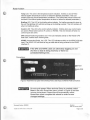
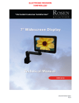
2. ROSENVIEW CONNECTIONS, INDICATORS AND CONTROLS
The front side of the RosenView unit houses the PS/2 keyboard connection , USB port,
Reset/Power button, and LED displays.
The plug in the lower left covers a connector used only by Rosen Aviation technicians.
Figure 1 RosenView front panel view showing connections, LEDs and ReseUPower button
PS/2 Keyboard Connection : Connect a keyboard to this connection to access setup screens
and customization screens.
USB Port: Connect the USB Flashdrive (thumbdrive) with customized files to the USB port to
import custom configuration files into RosenView, or connect an empty USB Flashdrive to export
a RosenView custom configuration to be loaded on to another RosenView or saved for later use
(see Section 4.9 on page 15).
Reset/Power: Press and hold the Reset/Power button for about one second and then release it
to reset RosenView; the system will cycle power and reboot.
To enter Test Mode, first remove 28V power from RosenView, and then while pressing and
holding in the Reset/Power button , turn on the 28V power supply. Continue to hold in the
Reset/Power button for a couple seconds and then release. After booting up, Test Mode will run
on the monitor.
The GPS and ARINC LEDs blink in unison for the first few minutes when RosenView is in Test
Mode.
LED Definitions:
HD (Hard Drive) LED: the HD LED remains off during normal idle operation and blinks
during HD access.
PC Power LED: This LED indicates three possible conditions:
i) This LED remains on during normal operation
ii) This LED blinks while the RosenView system is booting up
iii) This LED will remain off if a system error prevents boot up
Document Number: 9002602
Template: 4.2 ~"1. R<MsionA; 16 May, 2005
Revision:
G
Date: 16 January, 2006
Page 4 of 20
Rosen Aviation
Temp LED: This LED is the temperature alarm indication. It blinks on and off if the
internal system temperature is above or below the allowed parameters. Th is LED
remains off during normal temperature conditions. (The RosenView monitor screen will
be blank if the internal system temperature is above or below the allowed parameters.)
Briefing LED: This LED is the briefing active indicator. If a briefing command is given to
the unit, the ijriefing LED will blink as long as the briefing is active . This LED remains off
when no briefing is active.
Control LED: This LED is the control activity indicator. It blinks when any control inputs
are active (RS232 serial control, IR control, or RS485) . This LED remains off when no
control inputs are active.
GPS (Global Positioning System) LED: Th is LED indicates activity on the RS2 32 GPS
data input; it blinks when receiving data.
ARINC (Aeronautical Radio, Inc) LED: This LED indicates activity on the ARINC 429 data
input. The ARINC LED will blink as long as valid data is being received in the ARINC
interface IC.
mt NOTICE
If the GPS and ARINC LEDs are alternately toggling on and
off, then no data is being received, or there is a
connection/wiring error.
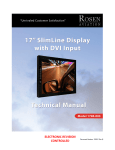
Connections:
Figure 2 RosenView rear panel view showing Power, Data Input and Monitor RGB connections
mt NOTICE
Do not cycle power! When technical Setup is complete , select
Done in the main RosenView menu (shown in Figure 4) and then
remove the keyboard. RosenView will automatically reboot.
RosenView must complete this reboot in order to save
changed settings.
Document Number: 9002602
Template· 4 2 3-6-FM. Revision A: 16 May. 2005
Revision:
G
Date: 16 January. 2006
Page 5 of 20
Rosen Aviation
3. GETTING STARTED
RosenView's default settings can be adjusted at the user's/installer's discretion. The following
subheadings detail each setting option and explain how to choose the desired option .
3.1.
RosenVi~w
Startup and Screen Navigation
The following assumes that RosenView has a power supply and is connected to a monitor.
1. With RosenView powered OFF, plug in a PS/2 standard PC keyboard into
RosenView's front-panel keyboard connection (see Section 2 for connection
information).
2 . Turn ON the 28V power supply ; wait a few minutes while RosenView goes through its
power-up sequence.
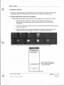
3. After the Startup screen has been displayed for more than 10 seconds, press the
keyboard menu key (shown below) to access the technical setup menus.
Figure 3 Pressing the Menu key activates the technical setup menu options shown below
Set Display Options...
l
Customize Setup.••
About RosenVI-
Select "About RosenView" to
view copyright and software
revision information
Done
Figure 4 Main RosenView Menu
Document Number: 9002602
Template: 4 .2.~.fM ; Revision A; 16 May, 2005
Revision:
G
Date: 16 January, 2006
Page 6 of20
Rosen Aviation
4 . To navigate through the menus. use the following table for control information.
Table 1. Keyboard Controls for RosenView Technical Setup Menu Navigation
Keyboard Key
Menu Key
~bkey
Description
Press this key to access the technical setup menus
Press the tab key to highlight options on the menu
Space Bar key
Press the space bar to select an option
Arrow keys
Use up and down arrow keys to change the selected options
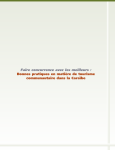
4. CHANGING DEFAULT OPTIONS
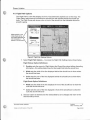
4.1. Setting Display Options
The options selected in the Display Units menu will appear in RosenView's information
screens or in the information bars located above and below the Rosen View map
(depending upon how the configuration is setup) .
1. Select the Set Display Options ... button and the Display Units menu will appear as
shown below.
2. Set each option as desired and then select Done to save changes and return to the
technical setup menus.
Display.Y.!'i~
---Options for measuring
distance
Display Units
o Imperial ft I mi
0 1i\vialion ft I kls
I
o Metric m I kph
Temperature Unils
o Celsius (*C)
0 Fahrenheit (*F)
What appears on the
initial screen will be
the Default Settings
(not necessarily as appears
in this document)
Time Format
---Options for measuring
temperature
--t--- Options for measuring time
o 12 Hour AM/PM
0 24 Hour
Done
Figure 5 Display Units Options
Document Number: 9002602
Template: 4.2. ~M; Revision A; 16 May, 2005
Revision:
G
Date: 16 January, 2006
Page 7 of 20
Rosen Aviation
4.2. Customize Setup
1. Select Customize Setup ... and the Customize Setup menu appears as shown below.
Customi~_~e_tup
Map Options ...
Right Path Options...
Pan-Zoom Options...
I
Slat.us View Options ...
Splash Options...
Colar Optiona...
Custom Configuration
Done
Figure 6 Customize Setup Menu
4.3. Map Options
1. Select Map Options ... to access the Map Settings menu shown below.
To allow visual comparisons between options, the map displayed on the right-hand
side will change as new options are selected.
Map
Se~n_l,ls
Oelaull Map Type
• Tettaiin
O Ro.d/Temlory
OPolltical
Globe Projection
e Or1hognpl-.ic
What appears on the
initial screen will be
the Default Settings
(not necessarily as appears
in this document)
0 Cylindricel
Font SUe
e Lwge.t
O lwg•
O Medi<.m
O Smoll..,.
O Smoll•I
Display Units is a
shortcut to the Display
Units menu detailed in
Section 4.1
Diaplooy Units
Figure 7 Map Settings Options
2. Set each option as desired and then select Done to save changes and return to the
technical setup menus.
Document Number: 9002602
Template 4.2
~M.
R8VISIOO A:, 16 May, 2005
Revision:
G
Date: 16 January, 2006
Page 8 of20
Rosen Aviation
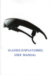
4.4. Flight Path Options
The Flight Path is a line that displays in front of and behind the airplane icon on the map. The
Flight History path shows a line behind the aircraft icon that indicates where the aircraft has
been. The Flight Route path shows a line in front of the aircraft icon that indicates where the
aircraft is going.
Flight Pati)i§!?_~tings
efliwht History;
Duration:
Width:
What appears on the
initial screen will be
the· Default Settings
30012 min
22
pix
Color:
u
(not necessarily as
appears in this document)
e R ight Route
Width: ~S: pix
Color:
=======!cit
Done
Figure 8 Flight Path Settings Options
1. Select Flight Path Options ... to access the Flight Path Settings menu shown below.
Flight History Option Definitions:
•
Duration sets the amount of flight history that Rosen View stores before discarding
information-this setting determines the line length that trails the aircraft icon
•
Width sets the width of the line displayed behind the aircraft icon to show where
the aircraft has been
•
Color sets the color of the line displayed behind the aircraft icon to show where
the aircraft has been
Flight Route Option Definitions:
•
Width sets the width of the line displayed in front of the aircraft icon to show the
route the aircraft will travel
•
Color sets the color of the line displayed in front of the aircraft icon to show the
route the aircraft will travel
2. Set each option as desired and then select Done to save changes and return to the
technical setup menus.
Document Number: 9002602
Template: 4.2.3-6.f'M: Revision A. 16 May, 2005
Revision:
G
Date: 16 January, 2006
Page 9 of 20
Rosen Aviation
4.5. Pan-Zoom Options
1. Select Pan-Zoom Options ... to access the Pan-Zoom Settings menu shown below.
The Pan feature allows the user to move North, South, East and West on the map by
pressing pan control buttons available with an optional controller.
The Zoom feature allows the user to zoom in and out on the map image by pressing
zoom control buttons available with an optional controller.
Pan-Zoom S.~~ngs
User Mode Settings
Timeout! ~~
What appears on the
initial screen will be
the Default Settings
Zoom Slepo: ~ ~
--'-='
Zoom Cycle Settings
(not necessarily as
appears in this document)
Steps:
,---2 . .
__
Duration: '
~ ~
...
Pacific Ocean
Figure 9 Pan-Zoom Options
User Mode Settings Option Definitions:
•
Timeout sets the amount of time (in seconds) that passes before Rosen View will
return to default cycling screens after a user zooms or pans
•
Zoom Steps establishes the number of zoom steps available for users manually
zooming in and out while viewing a map screen; each zoom step presents a map
view that is incrementally closer or farther away. The less steps you allow, the
greater the change between zoom steps
Zoom Cycle Settings Option Definitions:
•
Steps sets the number of zoom steps that occur when Rosen View is default
cycling through screen views without user interaction
•
Duration sets the amount of time each screen displays when Rosen View is
default cycling though screen views without user interaction
2. Set each option as desired and then select Done to save changes and return to the
technical setup menus.
Document Number: 9002602
Template: 4.2.3-0-FM; Revision A , 16 May, 2005
Revision:
G
Date: 16 January, 2006
Page 10 of 20
Rosen Aviation
4.6. Status View Options
1. Select Status View Options .. . to access the Status Settings menu shown below.
Status Settings allow options for how flight information is viewed on RosenView.
-
Track Status Bar
Status S~J19S
A ctive Views
111 Tr ack Status
El Fli ght Status
What appears on the
initial screen will be
the Default Settings
13 Fli ght St.mmary
(not necessarily as appears
in this document)
Summary Duration:
Summary Interval:
;
23
L___,;;:
-10:
Secondo
Seconds
--~
Pacific Ocean
Flight Status Bar
Done
Figure 10 Status Settings Options
Active Views Option Definitions:
•
Track Status is checked to show the upper status bar that displays altitude and
ground speed .
•
Flight Status is checked to show the lower status bar that displays (when
information is available) destination and time to arrive at destination.
•
Flight Summary is checked to enable three flight information screens to cycle on
screen at preset intervals. The three screens' information includes the following :
Screen One shows altitude, ground speed, heading, and outside air temperature
(when available).
Note: When using GPS data the temperature information will not be available.
Altitude ................
Ground Speed ......
Heading ........... ....
Outside Air Temp.
30097 Ft
384 Kts
045° NE
-44 °F
Figure 11 Information Screen
Document Number: 9002602
Template: 4.2 .~M; Revision A; 16 May, 2005
Revision:
G
Date: 16 January, 2006
Page 11 of20
•
Rosen Aviation
Screen Two shows destination distance, ETE (estimated time en route), ETA
(estimated time of arrival) , and local time at destination.
John F. Kennedy International. ..
New York
New York
United States
Distance ...... 1024 NM
ETE ............. 2 Hr 40 Min
ETA ............. 22:12 EDT
Local Time ... 19:32 EDT
Figure 12 Information Screen
Screen Three shows current location, latitude and longitude, and the current day,
date and time.
Figure 13 Information Screen
Use the following setting options to determine how often information screens
appear and how long they display before cycling to another screen .
+ Summary Interval time is set to determine how often an information screen
interrupts the map shown while RosenView is on and receiving data.
+ Summary Duration time is set to determine how long an information screen is
shown.
2. Set each option as desired and then select Done to save changes and return to the
technical setup menus.
Document Number: 9002602
Template: 4.2.3-6-FM; Rellision A; 16 May, 2005
Revision:
G
Date: 16 January, 2006
Page 12 of 20
Rosen Aviation
4.7. Splash Options (Startup Screen)
Splash options determine how the startup screen will interact with RosenView when the
aircraft is not tracking on the map.
1. Select Splash Options ... to access the Splash Settings menu shown below.
Idle Image Option Definitions:
•
Show On Idle:
There are three situations in which the startup screen will display:
i) when RosenView is first powered on and is booting up
ii) whenever RosenView is powered on and no data is being received
iii) when RosenView is receiving data but the aircraft is not flying
When the Show On Idle option is checked, and the aircraft is receiving flight
information data but is not in flight, the startup screen will display at preset intervals
until the aircraft is in flight and RosenView starts tracking.
•
Idle Interval time is set to determine how often the startup screen interrupts
RosenView when it is receiving data but the aircraft is not moving.
•
Idle Duration time is set to determine how long the startup screen interrupts
RosenView when it is receiving data but the aircraft is not moving.
r\lt:
Splash S~iµngs
.-
-·~'.
-·-
----- Ft
GS :
--- Kts
_,
Idle Image
e:'.ShQW On Idle'
--
Idle lntorv.i:
What appears on the
initial screen will be
the Default Settings
~
Seccnda
Idle Duration:
.
(not necessarily as appears
in this document)
10 ,.;. Secondo
Done
Figure 14 Map Settings Options
2. Set each option as desired and then select Done to save changes and return to the
technical setup menus.
Document Number: 9002602
Template 4 2.3-6-f"M, Re\llsion A 16 May, 2005
Revision:
G
Date: 16 January, 2006
Page 13 of 20
Rosen Aviation
4.8. Color Options
1. Select Color Options ... to access the Color Settings menu shown below.
To allow visual comparisons between options, the map displayed on the right-hand
side , and the menu on screen will change as new options are selected .
Color Settings Option Definitions :
Each color setting option is labeled on the image below to show what color is being
set during color selections .
"Values" would be shown here as
White if in-flight data were available
"Menu Title" is shown
here as White
"Status Background" is
shown here in
MidnightBlue
Color S~tti,'!9S
"Menu Background"
is shown here as
AliceBlue
MetiuTitte:
---.;;;:::~;;;;;.,,:~ "Units" here are shown
here as Aqua
Status Bad<g.-ound:
)lllihdni~~
Labels:
What appears on the
initial screen will be
the Default Settings
r;:=JYel_!.~-- ~·
(not necessarily as appears
in this document)
Units:
Value.:
LJWhil.e
"Shadow" color option
shows as a subtle
shadow backdrop on
text used in titles
..
u
,-~~
Done
~~~~ ··~~~--.@!:i~,~.,~~~-y/ E;)lndalo~
\>:1
_,,
Figure 15 Map Settings Options
"Labels" are shown
here as Yellow on text
found in information
screens
Altitude ................ 30097 Ft
Ground Speed ...... 384 Kts
Heading ............... 045° NE
Outside Air Temp. -44 °F
"Values" are also
shown in information
screens when in-flight
data is available
2. Set each option as desired and then select Done to save changes and return to the
technical setup menus.
Document Number: 9002602
Template: 4.2.3-6-FM; Revision A; 16 May. 2005
Revision:
G
Date: 16 January, 2006
Page 14 of 20
Rosen Aviation
4.9. Custom Configuration
If custom files have not been created (and they are desired), insert the RosenView
Configuration Tool CD into a PC , open Rosen View Configuration Tool User's Manual PIN
9003384 and complete the customization procedure.
1. Select Customize Configuration to access the Configuration Files menu shown
below.
.,.
Configuratlon
.,..,,..__Files
Item Selec tion
c;;u<~
O Backgreu>d lmege
O S1.art14> Image
o Cuslcm Icons
O Brlefinga
o S etup Options
lmporlllems
Ru lore F•ctary Items
I
E>porl llema
Smve AiteView Setup
load Smved S.tup
Done
Figure 16 Map Settings Options
When importing customized options from the loaded USS Flash Drive (thumbdrive):
2 . Connect the supplied thumbdrive with custom files to the RosenView USS port; allow
a minute for RosenView to recognize the thumbdrive .
3 . Select the items desired for customization (listed below Item Selection in the
Configuration Files menu).
Note: Selecting Setup Options from the Item Selection list will import changes
within the default settings that have been saved and exported to a thumbdrive.
For example, changes made through the Customize Setup menu options; screen
appearance, color schemes, etcetera.
This setting only works if a saved Rosen View setup has been exported to the
thumbdrive being used to import files.
4. Select Import Items; all items selected from the Item Selection list will import into
Rosen View.
Note: If Setup Options was selected from the Item Selection list, select Load
Saved Setup to activate those settings.
Document Number: 9002602
Template 4 2 3-6-f"M, Revision A: 16 May, 2005
Revision:
G
Date: 16 January, 2006
Page 15 of 20
Rosen Aviation
Configuration Files Button Option Definitions:
•
Import Items is selected to import custom items into RosenView so they become
active in the RosenView program. See the numbered procedure listed above for
more detail.
•
Restore Factory Items is selected to delete custom options and restore items
from the Item Selection list to their factory default settings.
•
Export Items is selected to export customized items (as selected in the Item
Selection list) to a thumbdrive .
The thumbdrive must be plugged into Rosen View's USS port for a minute prior to
selecting Export Items. This procedure is used to transfer a desired custom file
setup from one RosenView unit to the thumbdrive so the same configuration can
be imported onto another RosenView unit.
~.
Note that Setup Options will not export if Save RosenView Setup has not been
selected first to save the files. Select Save RosenView Setup before selecting
Setup Options and then Export Items.
•
Save RosenView Setup is selected to save all settings that have been changed
from default; these settings are not the custom configurations completed with
the RosenView Configuration Tool Software. The setup being saved in this
process includes all changes made through the Customize Setup menu options;
screen appearance , color schemes, etcetera.
Save RosenView Setup is used for two reasons:
i) To transfer a desired customization from one RosenView to a thumbdrive . Then
import the configuration to another RosenView unit as described in Section 4 .9,
numbers 1-5.
ii) To save the settings so that if exploring other setup options, one can simply
select Load Saved Setup to return to the saved configuration .
•
Load Saved Setup is selected to apply a saved customization of screen
appearance , color schemes , etcetera that was either saved using the Save
RosenView Setup option or Imported using the Import option.
5 . Set each option as desired and then select Done to save changes and return to the
technical setup menus.
Document Number: 9002602
Template· 4 2. ~-FM; Revision A'. 16 May, 2005
Revision:
G
Date: 16 January, 2006
Page 16 of 20
Rosen Aviation
4.10. Technical Setup Complete VERY IMPORTANT!
mt NOTICE
Do not cycle power! When technical Setup is complete, select
Done in the main RosenView menu (shown in Figure 4) and then
remove the keyboard . RosenView will automatically reboot.
RosenView must complete this reboot in order to save
changed settings.
Enter Test Mode and View your Configuration (recommended):
To enter Test Mode:
1. Remove 28V power from RosenView.
2 . While pressing and holding in the Reset/Power button , turn on the 28V power
supply-continue to hold in the Reset/Power button for a couple seconds and then
release.
After booting up, Test Mode will display a simulated flight on screen; all optional
controls are available during a simulated flight.
Note: Test Mode will only operate when no external data is being received by
RosenView. Any GPS or ARING data received will cause the RosenView system to
exit Test Mode.
Note: While in Test Mode, the internal IR remote sensor is active for receiving IR
remote control.
5. TECHNICAL SPECIFICATIONS AND TECHNICAL REFERENCES
5.1. Pinout Connections
mt NOTICE
RosenView Pinout information is found at www.rosenaviation .com
Click on the Support & Documentation tab to obtain Technical
documentation. Select Technical Drawings & Pinouts and then
choose mapping systems.
Document Number: 9002602
Template. 4.2 3-6-FM. Revision A; 16 May, 2005
Revision:
G
Date: 16 January, 2006
Page 17 of 20
Rosen Aviation
5.1 .1. Control Inputs
-tNOTICE
For Controller information, access www.rosenaviation.com
Click on the Product tab and then select accessories. Scroll down
to find RosenView externa l controllers .
Briefing Control Panel operation (PIN 0300-410 and 0300-411):
i) Import briefing files and allow RosenView to reboot (see Section 4.9 on page
15).
ii) Press Brief 1 (or the desired briefing) and then press Play to start the briefing;
the Briefing Control Panel's green LED will light while the briefing is active.
iii) Press Cancel to stop an active Briefing .
7-Button Controller (P/N 0300-407): The 7-Button Controller offers hard controls for
Zoom (in and out), Pan (N, S, E, and W) , and Return to return to the aircraft current
position .
RS485: RosenView can be controlled with RS485. For specifications please contact
Rosen Aviation at 541 .342.3802 .
IR Remote: RosenView can be controlled using Rosen Aviation's pre-programmed
Universal Remote Control (P/N 0500-005) . Other programmable remotes may be
programmed using the following information:
The RosenView IR receiver uses NEC style 32 bit encoding . In this encoding format,
there are 16 bits of actual information transmitted as part of a 32 bit frame. The 16 bits of
information is divided into 2 parts, the first part being an 8 bit device code, and the 2"d
part being an 8 bit function code. Each 8 bit portion of the transmitted code is followed by
the same code with each bit inverted. Most IR remotes using this format will have the
same device code for each button on the remote, and a unique function code for each
button . Listed below in hexadecimal format are the default codes used with RosenView:
Table 2. Hexadecimal Format Of Default Codes Used With RosenView
Control
Device Code
Function Code
Enter Button:
Ox80
Ox80
Ox80
OxBO
Ox80
Ox80
Ox80
OxOD
Ox08
Ox09
Ox11
Ox10
Ox52
Ox40
Pan Up:
Pan Down:
Pan Left:
Pan Right:
Zoom In:
Zoom Out:
Document Number: 9002602
Template. 4.2.3-6-FM. Revision A; 16 May. 2005
Revision:
G
Date: 16 January, 2006
Page 18 of 20
Rosen Aviation
As an example, the actual transmission of the Enter button would consist of the following bit
sequence:
Table 3. Actual Transmission of the Enter Button Bit Sequence
Lead In
Period
~
~
Device Code
Inverted Device
Code
dO d1 d2 d3 d4 d5 d6 d7
0 0 0 0 0 0 0 1
d0d1d2d3d4d5d6d7
1 1 1 1 1 1 1 0
Function Code
fO f1 f2 f3 f4 f5 f6 f7
00001011
Inverted Function
·code
fO f1 f2 f3 f4 f5 f6 f7
111101 00
.
Note that within each byte transmitted, the least significant bit is transmitted first.
If you need assistance in configuring a universal remote control to work with Rosen View, please
contact Rosen Aviation at 541 .342.3802 .
5.1.2. AudioNideo Outputs
RosenView has three available video output formats and one stereo audio output.
1. Analog RGB Output: Analog RGB connects to the 15-pin high density connector.
Analog RGB will produce the best results when using monitors sized 1 O" or above.
Note: When used with Rosen Aviation bulkhead monitors, a cabin controller can
switch between composite and analog RGB via the source input on the monitor's
external switch controller's connector. See the applicable monitor's technical manual
for specific source input toggle information.
2. S-Video Output: S-Video connects to coaxial pins A 1 and A2 on the main interface
connector (21 WA4).
3. Composite Video Output: There are also 2 separate composite video outputs on
pins A3 and A4 .
Audio Output: Audio Left, Right, and Ground connect to pins 1 through 3 on the 26pin Data Interface Connector.
Document Number: 9002602
Template: 4.2 :>6-FM; Revision A: 16 May, 2005
Revision:
G
Date: 16 January, 2006
Page 19 of 20
Rosen Aviation
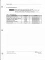
5.2. Technical References
.. NOTICE
Always check www.rosenaviation.com under the
Support&Documentation tab to ensure that you are working with
the most current revision of technical documentation.
Table 4. Technical References
Document Title
Part Number
Location
RS-485 Network Interface Protocol
9002933
www.rosenaviation.com
RosenView Outline and Installation Drawing
9003552
www.rosenaviation.com
Configuration Tool User's Manual
9003384
www.rosenaviation.com
RosenView User's Manual
9002603
www.rosenaviation.com
RosenView Briefing Control Panel
0300-410
www.rosenaviation.com
7-Button Controller
0300-407
www.rosenaviation .com
Document Number: 9002602
Template 4 2 3-0-FM. Revision A; 16 May, 2005
Revision:
G
Date: 16 January, 2006
Page 20 of 20
Rosen Aviation
RosenView Configuration Tool
User's Manual
Document Number: 9003384
emplate: 4.2 .3-6-fM; Revision A; 16 May, 2005
Revision:
C
Date: 12-28-05
Page 1 of 22
Rosen Aviation
1. REQUIREMENTS
The following requirements must be met in order to customize RosenView Software.
1.1. Operating System Requirements:
•
Windows XP
.. NOTICE
If problems are encountered while trying to run the Configuration
Tool customization software, ensure that the most current version
of Microsoft .NET Framework is installed on the PC.
The Microsoft .NET Framework install package is available
through a link on the RosenView Configuration Tool CD.
1.2. Human Interface Requirements:
•
PC , Keyboard , and mouse
•
CD ROM
1.3. Hardware Requirements:
•
Available USB Port
•
Minimum 250 Meg free hard drive space
Document Number: 9003384
emplate. 4 2.3-Q.FM. Revision />.:, 16 May. 2005
Revision:
C
Date: 12-28-05
Page 2 of 22
Rosen Aviation
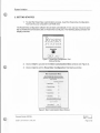
2. GETTING STARTED
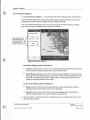
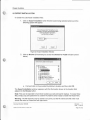
1. To start the RosenView customization process, insert the RosenView Configuration
Tool CD into your computer's CD ROM drive.
The RosenView configuration software should start automatically. If not, use your mouse to open
the CD ROM drive and double click on RosenView Config .exe. The following startup window w ill
display onscreen:
ROSEN
AVIATION
The~--ll•sedlO-
RosenView
Iii
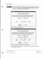
Figure 1 RosenView Configuration Tool
Startup Window
2. Click on Start to proceed to the Main Customization Menu window (see Figure 2).
3 . Click on Quit to exit the RosenView Configuration Tool startup window .
.
--
-
~
-
~-
-
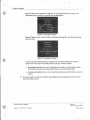
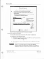
M•in Customizll1ion Menu
Eachofthehtodop~on•.,.lonkad lnorderlO
amomize on ol)Qoll. dick on the ~nk ond "1en follow
Do not select ~ons which you do not
l\e: direc:aons
""""'°
omomize
~d Cllstomi10lion
-- SIQl!uo Squn
0
-- Boc!sqpyn!I !mo9'
0
--~
0
- - points gfinttrtst
0
-
0
Cebin Bncljng
Old< on Ellp0!1 ln.-O ..._ )'DU
h,..... linished cus•om1un9 yo.. opoiorls.
E~
lnstalation
a.011nslollolion
Old< OuilID -
I
0uc
ond ,,...... )'Oii' progress.
Figure 2 Main Customization Menu Window
Document Number: 9003384
emplate 4 2 ~FM , Re\llsion A. 16 May , 2005
Revision:
C
Date: 12-28-05
Page 3 of 22
Rosen Aviation
3. CREATING A CUSTOM STARTUP SCREEN
The startup screen displays when RosenView is powered on and when there is no flight data
being input to RosenView. Users may change this screen to incorporate their own logo onto the
startup screen or to add aesthetics not offered in the default startup screen .
To change the default startup screen :
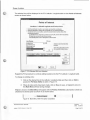
1 . Click on the Startup Screen link shown in Figure 2 to launch the Startup Screen
window shown below.
-tNOTICE
Note the Startup Screen window's listed requirements and
suggestions below. For assistance meeting requirements for best
image quality, see the Appendix section of this document.
Startup Screen
Startup Screen
Startup Screen requirements and suggestions:
• The startup image file format must be .bmp.
.jpg. or .git.
• There is no size requirement howe\ler, the
best image quaiity will be obtained when
the image's resolution matches RosenView's
screen resolution. which is set to 640x480.
Browse:
Clear
lWi_
Save
Cancel
Figure 3 Startup Screen Window
2 . Click Browse to open the file Open browse window shown in Figure 4.
Note: Ensure that the selection meets the requirements as listed in the Startup Screen
window shown above.
Document Number: 9003384
emplate· 4.2.3-6-FM, Revision 1'. 16 May. 2005
Revision:
C
Date: 12-28-05
Page 4 of 22
Rosen Aviation
[1Jfg]
Open
Look n:
[G
My Recent
Doc:unents
@
IO inages
3
~ (t)
d · li'WI·
IC) airer aft_icon
li:)poi_icon
[Si afterComplete
[Si beforeComplete
[3blank
Desktop
CJ
My Doc:unents
~
MyCoo¢es
~
My Network
Places
Aename:
Aes ol type:
j1mage Fies{".BMP;".JPG:.GIF)
~
Open
:::1
Cancel
Figure 4 Startup Screen File Open Browse Window
3. Use the Look in: field box to navigate to the desired file.
4. Click on the desired file and then click Open .
The Startup Screen window reappears and the selected image width and height is shown .
Options include: click on Save to change the background image , click on Browse to replace the
file, click on Clear to clear the file, or click on Cancel to return to the Main Menu with no selection.
5 . If satisfied with the selection , click on Save.
The Main Menu reappears and the Startup Screen customization check box is checked and
colored green as shown below.
I
Completed Customization
-- Startup Screen
Figure 5 Startup Screen Completed
Document Number: 9003384
emplate· 4.2 3-Q.FM: Re,,.;sion A'. 16 May, 2005
~
I
Revision:
C
Date: 12-28-05
Page 5 of 22
Rosen Aviation
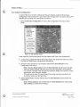
4. CREATING A CUSTOM BACKGROUND IMAGE
The background image is seen in the margins while viewing RosenView. For example, Figure 6
shows the default light-blue sky with clouds background . Notice the background shows through
RosenView's top and bottom banners.
Figure 6 Default Background: Light-Blue Sky With Clouds
To replace the default background image:
1. Click on the Background Image link shown in the Main Menu (Figure 2 on page 3) to
launch the Background Image window shown below.
-+NOTICE
Note the Background Image window's listed requirements and
suggestions below. For assistance meeting requirements for best
image quality, see the Appendix section of this document.
Background Image
Bockground lmoge requi<ements Md suggestions:
• The b8d<ground """9• file fooncl must be
.bmp. JP9- or .~.
• There is no size requirement however, tie
best im11ga qulllily Wll be obtained when
the image'• resolution m111Che1 RosenView's
screen resolution. which 1s set lo 640x480.
Oecr
Cencel
I
Figure 7 Background Image Window
Document Number: 9003384
emplate 4 2 3-6-FM. Rel/ISIOO A. 16 May, 2005
Revision:
C
Date: 12-28-05
Page 6 of 22
Rosen Aviation
2. Click Browse to open the file Open browse window (sim ilar to the window shown in
Figure 4).
3 . Use the Look in: field box to navigate to the desired file .
4 . Click on the desired file and then click Open .
The Background Image window reappears with options that include: click on Save to change the
background image, click on Browse to replace the file, click on Clear to clear the file, or click on
Cancel to return to the Main Menu with no selection .
5. When satisfied with the background selection, click on Save.
The Main Menu reappears and the Background Image customization check box is checked and
colored green as shown below.
-- Bocl<ground lmege
a
Figure 8 Background Image Customization Completed
Document Number: 9003384
emplate· 4.2 3-6-FM, ReVISlOO I\ 16 May. 2005
Revision:
C
Date: 12-28-05
Page 7 of 22
Rosen Aviation
5. SELECTING A CUSTOM AIRCRAFT ICON
The Aircraft Icon customization screen provides users the option of downloading an aircraft icon
from icon choices provided through the software, or downloading their own aircraft icon. The
selected icon will represent the aircraft that travels on the map when viewing RosenView.
To select an icon:
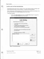
1. Click on the Aircraft Icon link shown in the Main Customization Menu (Figure 2 on
page 3) to launch the Aircraft Icon window shown below .
Aircraft Icon
Aircraft Icon
Click on one of these two links for
customizing the Aircraft Icon:
Browse for My Icon
Choose from Existing Icons
Close
Figure 9 Aircraft Icon Main Window
2. Click on Browse For My Own Icon to bring up the Aircraft Icon - Browse window as
displayed in Figure 10.
3. Click on Choose From Existing Icons to bring up the Aircraft Icon - Choose
window shown in Figure 11 .
Document Number: 9003384
emplate: 4.2.3-0-FM; Revision A; 16 May. 2005
Revision:
C
Date: 12-28-05
Page 8 of22
Rosen Aviation
-tNOTJCE
Note the Custom Aircraft Icon requirements listed in the Aircraft
Icon - Browse window below. For assistance meeting
requirements see the Appendix sect'ion of this document.
Aircraft Icon - Browse
Aircraft Icon - Browse for My Icon
Custom Aircraft Icon requirements:
• Aircraft icons must be a top-down view and be facing
North (up). as shown in the example below:
+
• The aircraft icon image format must be .bmp• .jpg.
or .git.
• Resolution is recommended to be 40x40 pixels. but
no more than 90x90.
"'The top-left pixel's color is transparent in RosenView.
Clear
Browse:
lif Save
Cancel
Figure 10 Aircraft Icon - Browse Window With Default Icon Shown In Example
4 . Click Browse to open the file Open browse window (similar to the window shown in
Figure 4).
5. Use the Look in: field box to navigate to the desired file.
Ensure that the selection meets the requirements as listed in the Aircraft Icon - Browse window
shown above .
6. Click on the desired file and then click Open .
The Aircraft Icon - Browse window appears, and the selected image width and height is shown .
7. Click on Save to return to the Main Menu.
The Aircraft Icon customization check box will be checked and colored green as shown in Figure
12 on the following page.
Document Number: 9003384
emplate: 4.2.3-0-FM: Revision A: 16 May, 2005
Revision:
C
Date: 12-28-05
Page 9 of 22
Rosen Aviation
--
-
-
-
-
-
- -- -
. -
- --
. - ---- . --
Aitctaft Icon - Choose
- --
-
-- - - -
-
Aircraft Icon - Choose from Existing Icons
Select one of the Icon Choices to see a preview.
To finalize y our decision, dick Save while your
selection is in the preview.
"1"he top-left pixel's color is transparent in RosenView.
Icon Choices:
blad COV•l.brn
bluesky.gif
bomber.bmp
citation.bmp
cornhusker.jpg
falcon.git
G150.bmp
Preview
+
Curren/
Cle er
he.wk.git
helicopter.jpg
milite.ry.gif
Ill Save
Cancel
Figure 11 Aircraft Icon - Choose Window
1. Click on an icon from the Icon Choices list box. The image will be displayed under
Preview on the right-hand side of the dialog box.
2. Click on the desired selection, and then click on Save to return to the Main Menu.
The Aircraft Icon customization check box will be checked and colored green as shown below.
Figure 12 Customized Aircraft Icon Completed
I
6. CUSTOMIZING POINTS OF INTEREST
The Points of Interest (POI) window allows users to include icons and information concerning
areas of interest. Such areas of interest may include personal properties or favorite building
locations. Users have the option of downloading an icon from choices provided through the
software, or download ing their own icon .
Document Number: 9003384
em plate: 4.2.3-6-FM; Revision A. 16 May, 2005
Revision:
C
Date: 12-28-05
Page 10 of 22
Rosen Aviation
To add points of interest to the RosenView program :
1. Click on the Points of Interest (POI) link on the Main Menu to launch the Points of
Interest window shown below .
.. NOTICE
Note the Custom Icon requirements and information listed in the
Points of Interest window below. For assistance meeting
requirements see the Appendix section of this document.
Points of Interest
Points of Interest
Locations - Latitude/Longitude and Custom Icons
• Oick the Add button to o.dd o. new location and input the coordino.tes.
• Oick the Edit button to change the coordinates of your existing locations.
• To o.dd an icon to your location. select the location below and do either of the
following procedures:
1) Oick Browse to search for a OJstom icon (.bmp file. around 16x16 resolution).
2) Select an icon from the list of icon choices.
"The top-left pixel's color is transparent in RosenView.
Icon Choices
Preview
, I
1 bm
2.bmp
3.bmp
4.bmp
5.bmp
6.bmp
Icon Location
Select an item from the left to
preview.
lJ#
Qt(
Y. 1
Latitude
I
direction
Oick OK to plo.ce the icon into
the selected location below.
I
Longitude
I
direction
Add
Edit
Browse...
[3&.loelete
£:1 Savt!
8111
Co.nee I
Figure 13 Points of Interest Window
2. Click the Add button to access the POI Data Editor as seen below in Figure 14.
The POI Data Editor automatically validates the data being entered. Figure 15 shows an example
of a message displayed when invalid data is entered .
Document Number: 9003384
emplate: 4.2.J.S.FM; Revision 1'. 16 May, 2005
Revision:
C
Date: 12-28-05
Page 11 of22
Rosen Aviation
-+NOTICE
To convert latitude and longitude degrees, minutes and seconds to
decimals visit www.fcc.gov/mb/audio/bickel/DDDMMSS-decimal.html on
the web; or search for other conversion sites.
POI Data Ed1tOT
Points of Interest Data Editor
Locations must be entered as decimal Latitude and Longitude coordinates. An example is
shown below. The format shown for entering OJstom points of interest is required. The
number of digits used mayvaiy; a minimum resolution of .001 degrees is suggested.
Letitude direction
N
10.53033
Latitude
direction
liil Save
Longitude
136.81656
Longitude
direction
W
direction
Cancel
Figure 14 Points of Interest Data Editor
POI Data Editor
Points of Interest Data Editor
Locations must be entered as decimal Latitude and Longitude coordinates. AA ex.ample is
shown below. The format shown for entering custom points of interest is required. The
number of digits used mayvaiy; a minimum resolution of .001 degrees is suggested.
Latitude direction
N
10.53033
Longitude
136.81656
direction
W
Ve.lid longitude values range from 0 to 180.
Latitude
direction
Longitude
direction
121 .3564
liiil Save
Cancel
Figure 15 Points of Interest Data Editor With Error Message
3. After completing the POI data input, click Save to return to the Points of Interest
screen as seen in Figure 16.
Document Number: 9003384
emp(ate· 4.2 3-6-FM, Re111sion A:. 16 May, 2005
Revision:
C
Date: 12-28-05
Page 12 of 22
Rosen Aviation
Pomts of Interest
Points of Interest
Locations- Latitude/Longitude and Custom Icons
• O ick the Add button to add a new location and input the coordinates.
• Oick the Edit button to change the coordinates of your existing locations.
• To add an icon to your location. select the location below and do either of the
following procedures:
1) Oick Browse to search for a custom icon (.bmp file. around 16x1 6 resolution).
2) Select an icon from the list of icon choices.
"The top-left pixel's color is transparent in RosenView.
-----E"
Icon Choices
2.bmp
3.bmp
4.bmp
5.bmp
6.bmp
Preview
Select an item from the left to
preview.
I
Oick OK to place the icon into
the selected location below.
OK
Icon I Location
ra
Latitude
d irection
I
Longitude
I
lll!dl&ft
direction
2
Add
Edit
Browse ...
~Delete
Cancel
Figure 16 Points of Interest Window After POI Information is Completed
To add an icon choice for a POI location:
1. Click on the desired location located in the POI Latitude I Longitude table.
2. Complete one of the following two steps:
a. Click Browse to search for custom icons; ensure that icons meet the requirements
as stated in the Points of Interest window.
OR
b . Click on an icon from the Icon Choices list box in the top half of the window and
then click OK .
.+NOTICE
Custom POI icons will show on the RosenView map when
zoomed in close . As the zoom levels retract, the POI icon will be
replaced by a symbol; from far out zoom levels nothing will show.
Document Number: 9003384
emplate: 4 2.3-6-FM: Revision A:. 16 May, 2005
Revision:
C
Date: 12-28-05
Page 13 of22
Rosen Aviation
The selected icon will be displayed in the POI Latitude I Longitude table on the Points of Interest
screen as shown below.
Points of lnter~st
Points of Interest
locations - Latitude/Longitude and Custom Icons
• Qick the Add button to o.dd a new location and input the coordinates.
• Oick the Edit button to change the coordinates of your existing locations.
• To o.dd on iron to your locabon, seled the location below and do either of the
following procedures:
1) Qick Browse to search for a custom icon ( bmp file. around l 6x16 resolution).
2) Seledon icon from the list of icon choices
"The top-left pixel's color is transparent in RosenView.
Preview
Icon O!oices
smiley.bmp
spirolblack.bmp
stororonge.bmp
Seledon item from the left to
preview.
il•••••'-.1
iiiiliniiik.iblmii.
Icon I Location
Lolitude
I
direction
Qick OK to place the icon into
the seleded location below.
OK
I Lon
itude
.,
direction
Add
Edit
Browse ...
(B;Joelete
Cancel
Figure 17 POI Window With Icon Selected
Repeat this POI procedure to continue adding locations into the POI Latitude I Longitude table.
To change an existing entry:
1. Click on the desired line in the Latitude I Longitude table and then click on Edit to
access the POI Data Editor as seen in Figure 14.
2 . When all entry points have been made, click on Save to save, or Cancel to return to
the Main Menu without saving changes.
If Save is chosen , the Main Menu will appear with the Points of Interest customization check box
checked and colored green as shown in as shown below.
-- points of Int~
Figure 18 Main Menu With POI Option Completed
Document Number: 9003384
emplate 4 2.~M. ReVISIOn ,... 16 May. 2005
I
Revision:
C
Date: 12-28-05
Page 14 of 22
Rosen Aviation
7. INSTALLING CUSTOM CABIN BRIEFING
Cabin Briefing options allow users to upload up to four cabin briefing messages. Briefings might
include welcome information, travel information, or in-flight services being offered .
These messages are created separate from RosenView and then uploaded to the software. See
file requirements llsted in the Cabin Briefing window shown below.
To add cabin briefings:
1. Click on the Cabin Briefing link shown in the Main Menu (Figure 2 on page 3) to
launch the Cabin Briefing window shown below.
Cabin Briefing
Cabin Briefing
Cabin Briefinq file requirements:
•
The briefing video format must be either
or .wmv.
Tote.I file size for all briefing files combined
may not exceed 150 megabytes.
No more than four total briefings a.re permitted.
.B.VI
•
•
Click Add to create a new briefing item and select
your desired file.
File Space Remaining: 150 MB
Briefin
Filename
Add
1Eoe1ete
liJ
Save
Cancel
Figure 19 Cabin Briefing Window
Document Number: 9003384
emplate: 4.2.J.6.FM; Revis1001', 16 May, 2005
Revision:
C
Date: 12-28-05
Page 15 of 22
Rosen Aviation
2. Click Add in the Cabin Briefing window to access the file Open browse window
(similar to the window shown in Figure 4) .
3. Using the file Open browse window, find and click on the desired cabin briefing file,
and then click Open .
The Cabin Briefing window will return with the selected file shown in the
Brir,~,ng
table .
Note: To change an existing file, click on an existing file line and then click on Browse to change
the file or Delete to delete the file .
4. Click Add to continue adding Cabin Briefing files.
Cabin Briefmg
Cabin Briefing
Cabin Briefinq file requirements:
•
•
•
The briefing video format must be .avi, .mpeg,
.mpg, .wrrr.t. or .o.sf.
Toto! file size for all briefing files combined
may not excsed 150 megabytes.
No more than four total briefings are permitted.
aid<. Add to create a new briefing item and select
your desired file.
File Space Remoining: 136.630144 MB
Briefin
1
2
3
Filename
Add
C:\Progro.m Files\Rosen Avio.tion\Co.. .
C:\Progro.m Files\Rosen Aviation\Co.. .
I C \F1oaram F1les\Rosen Aviet1on\Co ..
Browse ...
~Delete
-~Save
Cancel
Figure 20 Cabin Briefing Window With Three Files Added
5 . When finished selecting Cabin Briefings, click Save .
The Main Menu appears with the Cabin Briefing customization check box checked and colored
green as shown below.
Figure 21 Cabin Briefing Option Completed
Document Number: 9003384
emplate: 4.2.3-6-FM; Revision A:. 16 May, 2005
Revision:
C
Date: 12-28-05
Page 16 of22
Rosen Aviation
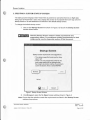
8. EXPORT INSTALLATION
To create the custom ized installation files:
1. Click on Export Installation when finished customizing selected options and the
following .~!~dow will appear.
Export lnstallat1on
Conned the provided Thumbdrive to your
computer's USB port use the Browse option
below to seled the Thumbdrive.
and then d ick on Export
Browse:
IIE"\
Cancel
Export
Figure 22 Export Installation Window
2. Click on Browse (if necessary) to access the Browse for Folder window (shown
below).
[1Jrg)
Br~e for folder
Browse for drive, folder Wo wii be 91Dred
8
~My C~
Eil .._. Local Disk(C:)
IB ~ CIMlW Drive (D:)
~
Eil ~ RemovableDisk(F:)
Eil ~ RemovableOisk(G:)
Eil 9 Removable Disk (H:)
IB ~ En,pojects on 'A.one' (I:)
Bl ~ Nik on 'Big Iron (Wl!l«e)' (P:)
Bl ~loictteron 'acme~~~:~.. -OK
JI
- ·-·
Cancel
~I
I
...
a. Find and click on the provided thumbdrive's location and then click OK.
The Export Installation window reappears with the file location shown in the location field
adjacent to the Browse button .
Note: Files can be exported to hard drive locations as well and kept for backup. To reuse these
files, simply copy and paste them to a blank Thumbdrive when ready to install into RosenView.
Warning: The file hierarchy may be saved to any drive, but the file names and file order must
remain the same or RosenView will reject them.
Document Number: 9003384
emplate: 42.34-FM, Revision A:. 16 May, 2005
Revision:
C
Date: 12-28-05
Page 17 of 22
Rosen Aviation
3. Click on Export and the RosenView user customization software will begin to
generate the FlightView files and save them to the selected location.
EKport Installation
Conned the provided Thumbdrive to your
computer's USS port use the Browse option
below to select the Thumbdrive.
and then click on Export
I
IE:\
Browse
Ill
fapon
Cancel
Figure 23 Export Installation Window In Progress
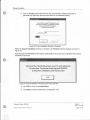
When the Export Installation window is complete, the Finished window displays as shown in
Figure 24.
Read through the Finished window before clicking OK. Ensure that you understand the process
necessary to proceed .
-
~
-
-
Finished
Remove the Thumbdrive from your PC and reference
RosenViewTechnical Setup Manual 9002602
to load this installation onto Rosenview.
OK
I
Figure 24 Export Installation's Finished Confirmation Window
4. Click OK to return to the Main Menu.
5 . Click Quit to exit the RosenView Configuration Tool.
Document Number: 9003384
Revision:
C
Date: 12-28-05
emplate: 42.3-6-FM: Revision A:. 16 May. 2005
Page 18 of 22
Rosen Aviation
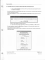
9. CLEARING FILES TO CREATE ANOTHER NEW CONFIGURATION
1. Click on Clear Installation to remove all the currently saved customization files from
the software workspace .
Ensure that saved back-up customization files exist on the hard drive if concerned with losing most
recently customized information.
When Clear Installation is clicked , a New Installation Confirmation window appears as shown
below:
New Installation Confirmation
·
This wl erase al osrent custom files. Click 'Yes' to start a New Installation or 'No' to cancel.
11
Yes
No
Figure 25 New Installation Confirmation Window
2. Click Yes to clear the file information and start a new installation, or No to cancel.
If a new installation is started , the Main Menu will appear with all customization option check
boxes cleared as shown in Figu re 26.
Repeat this document procedure as often as desired to create and save a variety of RosenView
customized options.
......
--·--------- - - - --
------.
"lolnCustomlZ&tlanMenu
Main Customization Menu
Each of1he fisted options ate linked. In order ID
01slomize ""option. dick on 1he fink a11d lhen foHow
1he dl18dions. Do not select options whicn you do not
went to OJstomize.
Completed C..stomitalion
-- StOl!Up Soun
0
-- Bpd<aroynd lmege
0
--~
0
- - Poi$ ot Interest
0
-- Gobin Bnefing
0
Click on Ei<port lnstollc6on when you
hove finished OISIOmlllng your opbons.
E.'<J)Ort Installation
Oeai lnstellehon
I
Quit
01ck Quij to exit and scve your progress.
Figure 26 Main Menu After Clear Installation
Document Number: 9003384
emplate: 4.2.3-6-FM: Revision A:. 16 May, 2005
Revision:
C
Date: 12-28-05
Page 19 of 22
Rosen Aviation
10. APPENDIX
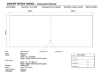
10.1 . How to Meet Custom Startup Screen and Background Screen Requirements
This procedure describes how to best create a custom startup screen or background screen to
match RosenView's 640x480 screen resolution .
The example procedure utilizes Photoshop. If Photoshop is not accessible , other graphics
programs may be used, or download a free trial of Photoshop from the Web
(www.adobe.com/products/photoshop/main.html select tryout under downloads in the leftside column and download Photoshop CS2) .
While RosenView can take any image and expand or shrink it to make it fit the required format,
it does not produce good results unless the image is close to a 640x480 screen resolution .
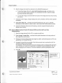
For best results, complete the following steps:
1. The images to be used in the screen may need to be opened and saved in a different
file format so that it can be placed later.
a. To save image(s) in a proper format, open the image(s) with Photoshop , click
File7Save As ... and save the image as an .EPS file; close the file.
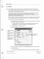
2 . Select File7 !few... to create a new file.
3. Change the settings in the new file as directed in the image below:
Change this setting
to 640.
Cancel
Ipixels
Ipixels
Ipixe1s1i'dl 3
Change this setting
to 480.
Change the resolution
to 300
~:
Change rontents to
background rolor
r.
IRGBcou
Leave settings
as pixels
i] .
I ransparent
Figure 27 Change settings for the new startup screen
4. Click OK and the new file will open ; select View7 fit on Screen in the main toolbar.
5. Select File7 Place ...
a. Browse for and select an image for the custom screen , and then click on Place.
Document Number: 9003384
emplate. 4 2 3-6-fM. Revision A:. 16 May. 2005
Revision:
C
Date: 12-28-05
Page 20 of 22
Rosen Aviation
6. Size the image and locate it as desired on the 640x480 background .
a. To size the image, click on it, select edit7transform7scale, and click on the
corner and drag to scale as desired; for a background screen, scale the image
such that it fills the entire space.
b. To move the image, click and hold the mouse on the image and move it by moving
the mouse.
·~
7. Continue to add images, change background colors, etcetera until the screen appears
as desired.
8 . Select File7Save As .. . and then save the file format as a .jpg, .gif, or .bmp file;
remember the file location to select it later in the RosenView customization process .
9 . Close the Photoshop file and exit Photoshop ; save the original Photoshop file as
desired when closing.
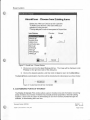
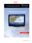
10.2. How to Meet Custom Points Of Interest (POI) and Aircraft Icon Size
Requirements
1. Open the image desired for the POI or custom aircraft icon.
2. Select lmage7 Image Size ... and look at the pixel dimensions in the top portion of
the Image Size menu screen .
3 . Whichever has the highest pixel size (height or width}, set that dimension to 40 for an
aircraft icon, or 16 for a POI icon.
4 . Increase the resolution as possible; if the file document size is reduced by half, the
resolution setting can be doubled.
For example, if the file document size were changing (due to changing the pixel size)
from 4 inches to 2 inches, an image with 72 resolution could be doubled to 144. If it
were changing from 4 inches to 1 inch the resolution could be quadrupled to 288.
5. Click OK.
rg:i
Image Size
OK
PixelDinensms: 4 IK
W.-11111:
~qrt:
I
lmiJ
t35
Heqrt.:
eesolrtm:
3 Ja\.I
3::J
Cancel
auto...
I
I
Il
Change the higher of
the two listed pixel
values as directed in
step 3.
-1 h:hes~
3 J~
~~.01-4
ooamentSlze:
Wi!!lh:
Ipixels
Ipixels
11319
f72
Ii"ches 3
Ipba!1s1n:tt 3
P !:.ooslr'MI Prqicrtms
P Resarc>te ~: I~s-o.o-c
---3-
J
Figure 28 Height Set to 480
Document Number: 9003384
emplate: 4.2.3-6-FM; Revision A; 16 May. 2005
Revision:
C
Date: 12-28-05
Page 21 of 22
Rosen Aviation
6 . Select File~Save As ... and then save the file format as a .jpg , .gif, or .bmp file;
remember the file location to select it later in the RosenView customization process.
7. Close the Photoshop file and exit Photoshop; save the original Photoshop file as
desired when closing .
Document Number: 9003384
emplate 42 3-6-FM. Re111slon A. 16 May. 2005
Revision:
C
Date: 12-28-05
Page 22 of 22