1
will NOT cause the fault LED to light, the unit must be driven by real-world input signals and the
fault must persist for several minutes!
===========
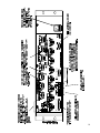
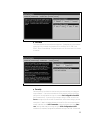
4. Test Jacks
The Test jacks give you access to any of the signals being sent to the front panel speaker (before
the gain potentiometer). These signal levels are at the exact same level as the cinema processor
output signals (unity gain) and can be used as a test point for system calibration.
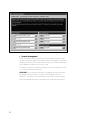
5. Emergency Bypass
This is an extremely powerful feature. If there should ever be a problem with the DCM or system
cabling, you have the ability to bypass all of the DCM active circuitry and get sound to the center
channel.
In the NORMAL position, the DCM performs normal monitor and crossover functions. In the
EMERGENCY position, the PROC center channel signal is routed to a passive crossover (no power
is required), and then to the center channel amplifier. In the EMERGENCY position, all amplifiers
except the center channel amplifier are put in Standby mode. There are level adjustments on the
rear panel for balancing the high frequency and low frequency output level.
==========
WARNING: Connecting improper frequencies can damage your speakers.
==========
B. Rear Panel Features
The DCM uses mass termination connectors which makes a QSC cinema sound system extremely easy
to wire together.
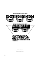
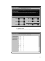
1. Amplifier DataPorts
One QSC amplifier DataPort includes all connections required to send two channels of audio from
the DCM to the amplifier input circuitry, and current and voltage information back from the two
speaker terminal outputs. Also included on this connector is remote on/standby pin which allows
the DCM to act as a master system power controller.
Computer industry VGA-style cables can be used to connect between the DCM and QSC amplifiers. However, make sure that your cable passes ALL connections between the two 15 pin connectors. See Appendix 1 for pinout information. Contact QSC if you would like to purchase specially
made cables.
The maximum output configuration on the DCM-1 is a 6 ch / 2-way, the maximum DCM-2 is a 6 ch
/ 3-way, and the maximum output configuration on the DCM-3 is a 8 ch / 3 way. In addition,
many parallel outputs (with separate processing) are included for additional theater configuration
flexibility.
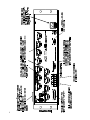
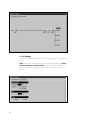
The rear panel labelling on the DCM has all of the information required by an audio installer.
When starting, write down the EXACT SPEAKER CONFIGURATION (for example, 8 channel, Tri-
14