1
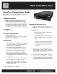
DataPort 10
Users Manual
www.CRU-DataPort.com
About CRU-DataPort
CRU-DataPort™ is a leading supplier of data security and storage
devices for computer systems. Founded in 1986 and based in
Vancouver, WA, USA, CRU’s DataPort removable storage
enclosures are used worldwide and have become the de facto
standard for physical data security and reliable drive removal
in government, education and corporate IT environments.
DataPort’s rugged design protects the drive during removal,
transport and storage while fans keep drives running cool
during operation. Most DataPorts have connectors rated for
25,000 insertions and are backed by some of the industry’s
best and most user friendly warranties.
CRU products are available through major distributors, OEMs,
VARs and a host of resellers and systems integrators throughout
the United States and abroad. For more information please
visit www.CRU-DataPort.com.
Table of Contents
About CRU-DataPort.................................................i
Product Description ...................................................1
Package Contents ......................................................2
Preparation for Installation.............................................3
Frame Installation ...................................................3
Mounting Hard Drive into Carrier ................................4
Operation ............................................................ 6
Power ............................................................ 6
Activity LED’s..........................................................6
Fan Failure Alarm ...............................................7
Trouble Shooting ......................................................7
Technical Support ...................................................8
Limited Product Warranty ........................................ 8
Product Remedies .....................................................8
Limitation of Liability ..............................................8
© 2005 CRU Acquisitions Group, LLC. ALL RIGHTS RESEREVED
No part of this manual may be used or reproduced in any form or by
any means, without prior written permission of CRU Acquisitions
Group, LLC.
This manual contains confidential and proprietary information of CRU
Acquisition Group, LLC which is protected by copyright, trade secret,
trademark and other intellectual property rights.
i
Product Description
The DataPort 10 comes with the installation documentation
you need for easy installation. The all metal enclosure is
sturdy and rugged to protect your data in all but the most
extreme environments. This product is designed for systems
that optimize space reserved for 5.25” bay devices.
Package Contents
The DataPort kit includes all of the necessary hardware to
install a 3.5” hard drive in a DataPort 10 and the DataPort
10 in a 5.25” drive bay. Before installing, please verify that
the following items have been included in the package.
Quantity
The overall dimensions for the DataPort 10 are:
37.2mm/1.46” H x 145.5mm/5.73” W x 200mm/7.87” L.
Description
1
DataPort frame assembly
The DataPort 10 consists of a frame and carrier with a top
cover. The frame can be fitted into any standard 5.25” halfheight drive bay.
1
DataPort carrier assembly
1
Metal cover
DataPorts allow you to easily remove a 3.5” SATA hard drive
from your PC or MAC. The DataPort carrier provides a simple
and inexpensive way to swap drives, transport data between
computers, and is also useful for on-line back-up and storage
of critical files.
1
Nylon screw for carrier cover (extra)
5
#6-32 x 1/4 flat head screws for drive
mounting
4
M3 x 5 pan head screws for frame
installation
2
Keys for lock
The DataPort 10 provides a switched power service to the
hard disk drive for 12V, 5V and 3.3V when connected in a
system that provides power thorough the 15 pin Serial ATA
conforming power connector.
Page 1
Page 2
Preparation for Installation
Note: To prevent data loss, read this manual thoroughly
before installing or operating the DataPort.
Before touching any electrical equipment, ground yourself
by touching the metal part of your computer chassis. This
discharges static electricity and helps prevent damage to
your computer. CRU-DataPort is not responsible for damage
caused by static discharge.
Tools Required:
· Phillips screwdriver
Other items that will be needed are:
· Computer users manual
7. Connect a power cable to the frame.
Locate an available 15-pin SATA power cable from the
computer power supply and plug it into the power plug
on the frame. For power supplies that don’t support 15pin SATA, please use the provided legacy to SATA power
adapter cable.
The frame installation is now completed.
Mounting a Hard Drive in the Carrier
1. Remove the top cover of the carrier.
The metal cover for DataPort 10 is secured by a nylon
screw. Remove the screw and slide the top cover off the
DataPort 10 carrier. (See Picture 1 for details)
Frame Installation
1. Power off your computer.
Turn off the computer and disconnect its power cord
from the electrical outlet. Before working on your
computer, wait one minute for any residual energy to
dissipate.
2. Remove the cover of the computer.
3. Locate an empty external 5.25” bay.
Identify the 5.25” half-height bay in which you plan to
mount the DataPort frame assembly. Remove any filler
plates that may be present.
4. Direct mount the frame assembly.
Slide the frame into the 5.25” bay from the front of the
PC case. Using the screws provided, secure the frame
assembly to the PC case using the frame’s side mounting
holes (bottom mount holes are also available on your
DataPort 10).
5. Rail mount the frame assembly.
If the drive bay requires mounting rails, install one on
each side of the frame. The mounting rails should have
come with your computer system.
Picture 1
6. Connect the data cable to the frame.
Locate a SATA data cable and connect it to the SATA
connector on the frame.
Page 3
Page 4
2.Install the hard drive in the carrier.
With most hard drives you will slide the hard drive in from
the front of the carrier and connect it to the carrier
board. (See picture 2 for details)
If the hard drive does not fit, remove the screw holding
the circuit board in the carrier. Place the hard drive in
the carrier, then connect the circuit board to the hard
drive. Secure the circuit board with the screw and then
secure the hard drive with the provided screws. (See
Picture 3 for details)
Picture 3
4. Insert the carrier into the frame assembly.
Ensure that the lock of the DataPort is in the “open”
(vertical) position. Position the carrier on the guide rails,
and then slide the carrier into the frame. Using thumb
pressure, fully seat the carrier in the frame and lock the
unit with the key lock.
You have finished the installation and your
DataPort 10 is ready for operation.
Operation
Picture 2
3. Attach the Temperature Control Cooling Sensor (TCCS)
to the top of the hard drive with an adhesive strip. After
the drive has been installed, replace the top cover and
secure it with the provided nylon screw.
Page 5
Turn on the Power
The lock on the DataPort locks the carrier in place and
also serves as the power “ON/OFF” switch. Turn the
lock 90 degrees clockwise to the “ON” position before
turning on the computer. When the computer is turned
on, the “Power On” LED (green light emitting diode
above the key on the frame assembly) is illuminated,
and your system should operate normally.
Activity LEDs
The DataPort 10 supports the Serial ATA II drive activity
feature. If the hard disk drive does not support Serial
ATA II the LED activity will be determined by the hard
disk drive; usually the LED will be off.
Page 6
Fan Failure Alarm
The fan failure alarm function is a standard feature on
the DataPort 10. If the cooling fan should fail, an alarm
will beep and the green LED on the upper left corner of
the DataPort will flash indicating fan failure. Removal
of the jumper on JP6 will silence the audible alarm on
the frame.
Important: READ THE FOLLOWING BEFORE REMOVING THE
CARRIER.
Removing the DataPort carrier while the computer is
operating is not recommended. If you need to remove
the carrier while the computer is running, observe the
following precautions:
Wait until the drive activity light has stopped, indicating
that no read/write activity is occurring. If your system
uses a disk caching program, ensure that all the data
has been written to the hard drive. Turn off the drive
by turning the key to the “OFF” (vertical) position.
The power LED will go off, indicating that the power
has been cut. Wait 10 to 15 seconds for the drive to
stop spinning, and then remove the carrier.
CRU is not liable for loss of data. It is the user’s responsibility
to follow these important procedures to safeguard data.
Trouble Shooting
No power
Make sure the lock of the DataPort is turned to the “ON”
position and the green power LED light is on. Check the
power connection on back of the frame.
Drive not recognized by computer
Ensure the carrier and frame are fully seated and the hard
drive is properly connected in the carrier. Ensure that the
SATA data cable is properly seated on the frame.
Fan Failure
For fan failure contact CRU Technical Support.
Page 7
Technical Support
You can contact CRU’s Technical Support Department by
visiting our web site at URL www.CRU-DataPort.com or
sending an E-mail message to [email protected].
Limited Product Warranty
CRU-DataPort (CRU) warrants the DataPort to be free of
significant defects in material and workmanship for a period
of five (5) years from the original date of purchase. CRU’s
warranty is nontransferable and is limited to the original
purchaser.
Product Remedies
CRU’s entire liability and the original purchaser’s exclusive remedy
for any breach of warranty, shall be, at CRU’s option, either (a)
return of the price paid or (b) repair or replacement of the hardware,
provided that the hardware is returned to CRU, with a copy of the
sales receipt or applicable documentation. Any replacement
hardware will be warranted for the remainder of the original
warranty period. These remedies are void if failure of the hardware
has resulted from accident, abuse, misapplication or modification.
(This will be determined by CRU.)
Limitation of Liability
The warranties set forth in this agreement replace all other
warranties. CRU expressly disclaims all other warranties,
including but not limited to, the implied warranties of
merchantability and fitness for a particular purpose and
noninfringement of third-party rights with respect to the
documentation and hardware. No CRU dealer, agent or
employee is authorized to make any modification, extension,
or addition to this warranty. In no event will CRU or its
suppliers be liable for any costs of procurement of substitute
products or services, lost profits, loss of information or data,
computer malfunction, or any other special, indirect,
consequential, or incidental damages arising in any way out
of the sale of, use of, or inability to use any CRU product or
service, even if CRU has been advised of the possibility of
such damages. In no case shall CRU’s liability exceed the
actual money paid for the products at issue. CRU reserves
the right to make modifications and additions to this product
without notice or taking on additional liability.
Rev. 1.0
Page 8