1
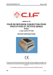
REFLOW OVEN FT01
Version 0602
www.cif.fr
REFLOW OVEN
FT01
(Article number F31105)
User’s Manual
This document contains manufacturer’s information which is protected by copyright. All rights reserved. This document
cannot be copied, reproduced or translated without written authorisation from C.I.F.
Information contained in this document can be modified without prior notice.
CIF
1 / 12
REFLOW OVEN FT01
Version 0602
E.C. CONFORMITY CERTIFICATE
Us,
C.I.F
Circuit Imprimé Français
11 rue Charles Michels – 92227 Bagneux Cedex France
Tel 33 01 45 47 48 00 FAX 33 01 45 47 16 14
email : [email protected] - web : www.cif.fr
We certify under our responsibility that this product conforms to European Economic Community
standards :
FT01 oven
In conformance With European guidelines,
(89/392/CEE – 89/336/CCE) and to EN60-204-1 standard
(F)
Déclaration du constructeur
La société C.I.F. – 92220 BAGNEUX, France, certifie que le produit répond bien aux
directives de la Communauté Economique Européenne.
(GB) Manufacturer declaration :
C.I.F. company – 92220 BAGNEUX, France, herewith declare that this product
conforms to E.E.C. regulations.
(D)
Hersstellererklärung :
Hiermit erklärt die Firma C.I.F. S.A. – 92220 BAGNEUX, France dass dieses produkt
der Richtlinie EWG entspricht.
Conforms to the following standards
In accordance with the following European Decrees :
•
•
•
Directives 73/23/EEC for low voltage machines amended by 93/68/EEC
Directives 98/37 EC for Machines
Directives EMC 89/336/EEC amended by 92/31/EEC and 93/68/EEC
Bagneux, May 14th 2001
CIF
Authorised signature
M. Bernard ANDRIOT,
2 /12
REFLOW OVEN FT01
Version 0602
Table of content
TABLE OF CONTENT ............................................................................................................................ 3
1.
GENERAL INFORMATION............................................................................................................. 4
1.1 INTRODUCTION .............................................................................................................................. 4
1.2 W ORKING WITH FT01..................................................................................................................... 4
1.3. TECHNICAL SPECIFICATIONS ........................................................................................................... 4
2.
TRANSPORTATION ....................................................................................................................... 5
3.
SAFETY........................................................................................................................................... 5
4.
INSTALLATION .............................................................................................................................. 6
4.1 FT01 UNPACKING .......................................................................................................................... 6
5.
START UP....................................................................................................................................... 7
5.1 SUGGESTIONS ............................................................................................................................... 7
5.2 RECOMMENDED SETTINGS .............................................................................................................. 7
6.
OVEN USE ...................................................................................................................................... 8
6.1 FRONT PANEL ................................................................................................................................ 8
6.2 OVEN START UP – CONFIGURATION ................................................................................................ 9
6.3 REFLOWING PROCESS .................................................................................................................. 10
6.4 OPERATING PROCESS - PLAN.......................................................................................................... 10
7.
MAINTENANCE, REPAIR & TECHNICAL SUPPORT ................................................................ 11
7.1 MAINTENANCE ............................................................................................................................. 11
8.
PROFILE EXAMPLE..................................................................................................................... 12
CIF
3 /12
REFLOW OVEN FT01
Version 0602
1.General Information
1.1 Introduction
Thank you for choosing the FT01 reflow oven. To get optimal satisfaction from this machine,
please read these instructions carefully. If you should lose this instruction manual, you can
receive a new one free of charge by specifying the date of purchase and series number of
the model.
The FT01 reflow oven is designed to weld hybrid or SMT boards, and to polymerize
serigraphy adhesives and inks. This equipment is suitable for use with prototypes as well as
small series.
1.2 Working with FT01
•
•
•
Use FT01 only for reflow soldering of hybrid circuits and SMT boards and for serigraphy
adhesives and inks polymerization.
Incorrect oven programming can lead to overheating the board and even burning it.
Never let the machine operate without supervision.
1.3. Technical Specifications
Dimensions : 370 x 455 x 320 mm (L x w x h)
Working area : 170 x 290 mm
Heating system : 2 x 1 kW quartz heating elements
Electrical supply : 220/240-Volts, 50-60 Hz (110 Volts on request)
Power supply : 2,2 KW
Net Mass : 13,5 Kg
Noise level when operating < 50 dB (A).
Heater :
Thermal stability time: approx. 4 mn
3 levels
- cooling time from 0 to 5 minutes
- preheating time from 0 to 5 minutes
- reflowing time from 0 to 5 minutes
Stand-by temperature from 0° to 250°C
Preheating temperature from 0° to 250°C
Reflowing temperature from 0°C to 250°C
Working temperature
To be used at room temperature from 5°C to 35°C.
CIF
4 /12
REFLOW OVEN FT01
Version 0602
2. Transportation
Before unpacking, check that the packing materials show no signs of impact. If they do,
check the machine’s condition immediately and inform the transport company. If you do not
make the necessary remarks on the freight documents, you lose all rights to file a claim with
insurance companies.
3. Safety
PLEASE NOTE :
During operation, if ON/OFF switch is activated or Stop button pushed, the oven remains
warm inside. A board which remains inside at that moment could be damaged by the high
temperatures.
A HOT OVEN DOES NOT COOL INSTANTANEOUSLY.
DO NOT PUT YOUR HAND INSIDE THE OVEN.
•
•
•
•
•
•
•
•
•
•
•
Do not make any internal adjustments or repairs by yourself
Make sure that you place only compliant materials
Do not introduce inflammable or explosive materials into the oven.
Put the oven in a well-ventilated area where it won’t be a fire hazard.
Make sure that the oven is not switched on and that it is completely cooled before
cleaning.
Wait for the oven to cool 30 minutes before any manual intervention.
Use only soft clothes and a non-aggressive detergent.
Do not use cleaning solvent or sprays.
Do not try to clean the inside of the oven, this action should be done by an authorised
maintenance technician during preventive maintenance.
After any technician intervention, carry out a thorough check to ensure safe equipment
operation.
Use heat-proof gloves to handle welded circuits.
CIF
5 /12
REFLOW OVEN FT01
Version 0602
4. Installation
4.1 FT01 unpacking
Carefully unpack the oven and keep the packing materials in case you need to move the
oven at a later date.
Check that the following elements are packed with your oven :
• FT01 oven
• User’s manual !
CIF
6 /12
REFLOW OVEN FT01
Version 0602
5.Start up
5.1 Suggestions
• Read the entire manual and follow our methods before trying yours.
• Keep this manual near the oven and follow safety instructions.
• To guarantee optimal results, keep your oven clean and in good operating condition.
• Do not let the oven operate without supervision.
• When researching a temperature profile, start with the lower temperatures in order to
avoid burning the board and the components.
• Avoid any draught around the machine: these could modify your temperature profile.
5.2 Recommended settings
Using the settings recommended below, you will be able to solder (weld) most of the boards.
On the other hand, we cannot guarantee that these settings correspond perfectly to your
application and you will have to first assess the result before deciding whether you should
use your own settings. When you want to find the right settings for your board, start with the
lower temperatures. If you begin with the higher temperature, you risk starting a fire by
igniting an overheated board. If you see that the board is overheated, open the drawer
immediately to take it out.
Configuration example :
Battery tester board (Ref.: F52171) format 20 x 40 mm
Number of components : 7
Green long-oil varnish
No lay-out plan
“P0” program
Oven temperature setting
Cooling time (after reflowing)
127°C
2 minutes
“P1” program
Preheating time
Preheating temperature
1,30 minutes
130°C
“P2” program
Reflowing time
Reflowing temperature
CIF
30 seconds
180°C
7 /12
REFLOW OVEN FT01
Version 0602
6. Oven use
6.1 Front Panel
Program selection button (A)
Program display (B)
Temperature display (C)
Temperature selection buttons (D)
Cycle time display (E)
Cycle time selection buttons (F)
Cycle start (G)
On/off (H)
CIF
8 /12
REFLOW OVEN FT01
Version 0602
6.2 Oven start up – Configuration
Oven configuration is easy to set and includes three basic phases: oven preparation phase,
preheating phase, and reflowing phase.
For this, 3 programs are available : P0, P1, and P2. The selection is made by pushing on the
button (A).
The P0 program enables you set the oven preparation phase which includes the oven
temperature before the reflowing cycle starts and cooling time at the end of the cycle.
(This time is the necessary time to reach this temperature).
In our configuration example (see paragraph 5.2.), the P0 program will be configured as
follows:
Switch on the appliance by pushing the On/off button (H)
The program (P0) can be selected by pushing the button (A)
Use the temperature selection buttons (D) to display 127°C (C)
Use the time selection buttons (F) to display 2 minutes (E).
The P1 and P2 programs enable you to set the reflowing cycle which includes the preheating
and reflowing steps. The preheating step prepares the solder paste, and the reflowing step
enables you to reach alloy melting temperature.
In our configuration example , the P1 program is configured as follows :
• the program (P1) can be selected by pushing the button (A)
• use the temperature selection buttons (D) to display 137°C (C)
• use the time selection buttons (F) to display 1,30 minutes (E).
In our configuration example (see paragraph 5.2.), the P2 program is configured as follows :
• the program can be selected (P1) by pushing the button (A)
• use the temperature selection buttons (D) to display 180°C (C)
• use the time selection buttons (F) to display 30 seconds (E).
After programming the preheating and reflowing phases (P1) and (P2), push the button (A)
once again. The cycle corresponding to the oven temperature-setting phase (E0) will
automatically start, displays (B) and (E) will be on standby, temperature display (C) will
indicate the oven temperature.
When the programmed temperature is reached (P0 programming), the reflowing cycle is
ready to be started up (see paragraph 6.3.).
The choice of time/temperature instructions depends on many criteria, including the nature of
the product used (soldering paste, adhesive, etc.), board dimensions, number and density of
components on the board, lay-out plan presence, etc. Therefore, it is essential for you to
read attentively and respect all product recommendations. It is also important to carry out
tests and take note of all setting parameters.
The last reflowing cycle parameters are kept in memory. The next time the oven is started
up, it will be preheated until the last recorded value is reached.
CIF
9 /12
REFLOW OVEN FT01
Version 0602
6.3 Reflowing process
Open the drawer and set the board on the plate. The reflowing cycle is triggered by pushing
on the cycle start button (G).
If the cycle has been interrupted by opening the drawer, you will have to start a new
complete reflowing cycle. To do so, wait until the oven temperature reaches the programmed
stabilisation temperature and press the button (G).
At the end of the preheating and reflowing cycles (E1) & (E2), the oven goes into the cooling
phase (E3) for the time programmed in (P0). Wait until cycle completion before opening the
drawer to take out the board.
Warning !!!
At this point the board is still at a high temperature; to avoid burns, do not touch it
with your hands. Use pliers or a protective glove to take the board out.
A new cycle can only be started when the temperature of the “oven temperature setting”
programmed in (P0) is reached, i.e. 127°C in our example.
6.4 Operating process - plan
Switch on the machine by pushing the On/Off button (H)
The oven reaches preheating temperature in P0
Open the drawer, put the SMT board on the grid then close the drawer
Wait for the oven to reach the preheating temperature (P0) again
Trigger reflowing cycle by pressing the G button
Flow activation cycle (E1) starts up to reach C1 temperature within T1 time
Reflowing cycle (E2) starts up to reach reflowing peak determined by T2 time and CE
temperature
Cooling cycle (E3) is triggered
At the end of the cycle (E3), open the drawer and let the board cool briefly
Take out the board and close the drawer
The oven reaches preheating temperature (P0).
The oven is ready for another cycle.
CIF
10 /12
REFLOW OVEN FT01
Version 0602
7. Maintenance, Repair & Technical Support
7.1 Maintenance
•
•
•
•
•
Clean the oven once a week with a soft cloth.
To avoid damaging the oven, do not use cleaning products inside it.
Do not use the oven to cook food products.
In the event an incident occurs on your machine, do not try to dismantle or repair it by
yourself.
Call your supplier or an authorised after sales department.
KEEP IN MIND THAT A CLEAN MACHINE WILL OPERATE CLEANLY.
All repairs must be carried out by a qualified technician authorised by CIF. Only
original parts supplied by CIF can be used.
For all questions relative to the FT01 oven, please contact the CIF technical
departments.
The more specific you are in explaining your problem, the easier it will be find a
solution. Before calling, please write down the symptom description to clarify the
request.
CIF
11 /12
REFLOW OVEN FT01
8.Profile
Version 0602
example
Use the following graph to set a temperature profile
T (ºC)
2 50
2 25
2 00
18 6
1 50
1 00
50
0
0
1
2
3
4
t (min)
CIF
12 /12