1
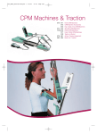
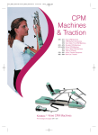
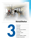
Centura
Centura 5
User manual
Before use, please read this document.
Kinetec reserves the right to effect technical modifications.
EN
467896351 – 05-2011
Série 5
Notice Originale
Adresse SPR+Logo Kinetec-New
SUMMARY
Page
DESCRIPTION
2-5
ASSEMBLY & TRANSPORT
6
USE OF THE HAND CONTROL
7-18
INSTRUCTIONS FOR USE
19-25
ACCESSORIES
26
PRODUCT INFORMATION
27-29
Select your language
SEE PAGE 7
Warning and Safety instructions
Warning:
The physician/physiotherapist defines the protocol and ensures that it is
correctly implemented (adjustments, session time and frequency of use).
Warning:
Run a cycle with the device unloaded before installing the patient on the
machine.
Warning:
For optimum safety, always give the hand control to the patient before starting
the system. The patient must know the start/stop/reverse function on the hand
control, see page 8.
Warning:
To avoid the parameters being changed, lock the machine’s hand control before
giving it to the patient.
Warning:
Danger, risk of explosion: Do not use the machine with anaesthetic gas or in an
environment that is rich in oxygen.
Warning:
To avoid all risks of electric shock, the machine should only be connected to a
power supply that has protective grounded pin.
Warning:
Before using this machine, always check that the electrical socket is in good
condition and is suitable for the splint power supply cord. Only use the original
cable supplied with the machine. Check that the cables remain free around the
device so that they do not get damaged.
Warning:
Before using this machine, always check that the machine is not damaged, in
particular the protective housings.
Warning:
In case of electromagnetic interference with other devices move the device.
Warning:
Please do not touch the moving parts while the unit is running, pinching risk.
Warning:
Modifying the machine in any way is strictly forbidden.
Warning:
Before each use, always check that the red knobs under the chair have been
tightened (see page 6).
Warning:
Before each use, always check that the various locking knobs have been
tightened (see pages 3 and 4).
Centura
1/29
EN
DESCRIPTION
DEFINITION
The KINETEC Centura is a upper extremity PASSIVE mobilisation device enabling the following movements:
• Abduction / Adduction from 20° to 160° in an exterior rotation position.
• Abduction / Adduction from 20° to 160° with the elbow in a flexed position.
• Internal rotation 60° to external rotation 90°.
• Combined movements: Abduction / Adduction from 20° to 160° and external Rotation from -30° to 90°.
• Flexion / Extension from 20° to 180°.
• Horizontal Abduction from -30° to 110° (available on Centura 5)
• Indications
• Total shoulder replacement
• Repeated dislocation of the humerus
• Rotator cuff injury
• Upper humerus fractures
• Scapula fractures
• Acromioplasty
• Capsulotomy
• Arthrolysis
• Synovectomy for Rheumatoid Arthritis
• All type of shoulder styffness joint
• Clinical Benefits
• Breaks the cycle of trauma, inflammation and the loss of range of motion
• Prevents joint stiffness
• Speeds the recovery of post-operative range of motion
• Maintains the quality of the articular surface
• Reduces pain and oedema
• Promotes articular cartilage healing
• Reduces hospitalization time
• Reduces the need for pain medication
• Contraindications
• Unstable fractures.
• Spastic paralyses.
• Uncontrolled infection.
• The machine are not adapted for patients height more 2m(6’7”) or under 1.4m(4’7”).
Centura
2/29
EN
DESCRIPTION
COMPLIANCE:
The KINETEC Centura complies with the standards of Directive 93/42/EEC, and bears the CE
mark.
The KINETEC Centura complies with the standards in force (IEC 601.1.2) concerning the
electromagnetic compatibility of medical devices and IEC 60601-1 concerning electrical safety.
The KINETEC Centura meets the requirements of the Machinery Directive No. 2006/42/EC.
DESCRIPTION • COMPONENTS
KINETEC Centura consists of the following components:
4
6
1 – Chair
2 – Frame
3 – Wheels
4 – Transport handle
5 – Arm rest knobs
6 – Arm rest
7 – Hand control support
7
1
5
3
2
12
8 – Locking of the right/left sliding
9 – Locking of the up/down sliding
10 – Chair locking knob
11 – Locking of the abduction motor
12 – Abduction motor
13 – Shoulder depth sliding lock
8
13
11
9
Centura
3/29
10
EN
DESCRIPTION
ABDUCTION ASSOCIATED WITH ROTATION SPLINT
14
18
15
22
17
16
21
14 – Arm length setting lock
15 – 90° elbow splint
16 – 90°elbow splint lock
17 – Rotation motor
18 – Elbow splint support lock
19 – Forearm length setting lock
20 – Forearm slider
21 – Right/left bean swivel lock
22 – Forearm splint
19
20
ABDUCTION OR FLEXION SPLINT
26
18
24
23
25
18 – Elbow splint support lock
23 – Swiveling splint support
24 – Elbow flexion setting lock
25 – Arm splint
26 – Arm splint lock
27 – Forearm length setting lock
27
HORIZONTAL ABDUCTION SPLINT (available on Centura 5)
18
14
28
28 – Horizontal abduction column
14 – Arm length setting lock
18 – Elbow splint support lock
29 – Elbow support older
30 – 90°elbow splint lock
19 – Forearm length setting lock
20 – Forearm slider
30
19
20
Centura
4/29
EN
DESCRIPTION
DESCRIPTION • ELECTRICAL
4
1 – Supply cable connector switch
2 – Fuse
3 – ON/OFF switch
4 – Hand control lock switch
5 – Defect or power light
6 – Motor or hand control connectors
7 – Hand control location for transport
8 – Hand control
3
6
3
7
2
8
11 12
24 10
1
13
99
15
14
16
17
18
23
20
19
21
Centura
9 – Liquid-crystal display
10 – Flexion/extension
11 – Abduction/adduction
12 – Rotation
13 – Abduction/adduction synchronized with rotation
14 – Lower limits setting
15 – Upper limits setting
16 – Increase / decrease
17 – START
18 – STOP
19 – FORCE
20 – SPEED
21 – PAUSE
22 – TIMER
23 – PROGRAM access
24 – Horizontal abduction
22
5/29
EN
ASSEMBLY & TRANSPORT
BASE ASSEMBLY
- Remove all the components from their packaging.
- Place the chair (1) on the floor; we recommend that two people carry out this operation. Take
care not to trap your fingers.
- Straighten up the back of the chair (2).
The tilting axis (3) must always be in good condition.
Never use the splint without it.
- Lock the back of the chair by tightening the red knobs (4).
- Before using this machine, we recommend that you always check that these knobs have
been tightened.
1
2
4
3
4
- Place the Abduction motor (5) on right or left,
depending on the limb be moved.
- The other components to be used depend on the
selected movement (see page 20 to 25).
5
UNIT TRANSPORT
7
For easy transport of the unit, it features 2 wheels (6) and a
handle (7).
Place the arm support as close as possible to the chair to limit
the overall dimensions and help balance the unit.
Place your foot as indicated to balance the unit.
You can adjust the height of the handle with knob (8).
Centura
6/29
6
8
EN
USE OF THE HAND CONTROL
ELECTRICAL CONNECTION: SAFETY FIRST
KINETEC Centura is a type B class I device.
Before connecting the device to the power supply, check that the mains
voltage matches that shown on the plate (100-240 V~ / 50-60 Hz) below
switch ON (2).
The connectors can be plugged in any one of the sockets
(the sockets are not assigned to a specific connector).
2
1
Connect the power supply cable (1).
IMPORTANT
Check that the electrical socket is in good condition and is
suitable for the splint power supply cord. The latter complies
with current standards and has a grounding socket.
The plug may be connected to any standard socket.
The socket must however have a grounded pin.
To connect the power supply, only use the original cable
supplied with the machine.
Check that the cables remain free around the device so that
they do not get damaged.
Check that the machine is not damaged, in particular the
protective housings.
3
Watch out for the position of the motor cables,
they must remain clear around the machine.
Wrong position
Good position
STARTING THE UNIT
Switch on the unit (2).
The indicator light (3) lights up, the machine carries out an auto-diagnostic, and then the display
shows:
Your KINETEC Centura is ready to be used.
FLEX/EXT
30
STOP
15
130
CHANGING THE DISPLAY LANGUAGE
Press the following buttons simultaneously:
to change the display language.
Press the
and
, followed by
or
button to confirm,
then switch the machine off and then on again to apply the changed display language.
Available languages: English, French, German, Italian and Spanish.
Centura
7/29
EN
USE OF THE HAND CONTROL
LOCKING THE HAND CONTROL SETTING
This function allows the physician to authorise or block
access to changing the movement parameters.
4
The switch (4) has 3 positions:
Fully locked position
The only functions that are possible are reading
the operational settings and operating the
START/STOP function.
Fully unlocked position
All the operational settings can be changed.
Semi-locked position
The program can still be changed and the lower
and upper movement limits can still be modified;
the START/STOP function is still accessible.
Double locking (soft locking)
Simultaneously press the
and
keys to lock the hand control,
the display shows "LOCK". To unlock the hand control, simultaneously press
the
and
keys; the display shows "UNLOCK".
You cannot change the parameters; if you try the display shows: "LOCK SOFT».
We recommend that you lock the hand control
when you give it to the patient.
START/STOP/REVERSE FUNCTION
As with all KINETEC systems, KINETEC Centura is equipped with a
START/STOP/REVERSE function.
Press the
key of the hand control. The movement stops.
The display reads STOP
Press the
key of the hand control. The movement starts
in the opposite direction and the display reads RUN.
Caution: For optimum safety,
always give the hand control to the patient before starting the system.
Procedure to stop the machine:
To stop the machine’s movement: Press the
key
To switch power off: press the ON / OFF switch (see page 7)
Centura
8/29
EN
USE OF THE HAND CONTROL
RESET TIME FUNCTION
This function allows one to read the running time since the last resetting of the counter.
Beginning
Keys to press
To stop the unit
Display
Remarks
FLEX/EXT
50 STOP 15 100
Check if the locking switch is
in the following position
or
Press simultaneously on the
2 keys
REST TIME 125H
Reset: Limit low
The display indicates the
running time since the last
resetting.
To reset the counter, press
the key
REST TIME 125H
Reset is done
The counter is now reset.
Or
After 5 seconds, the reset
function switches off and the
running time remains in the
memory.
FLEX/EXT
50 STOP 15 100
How to choose a movement
The movement can only be changed when the machine is stopped
and the locking switch is in the unlocked position
or
You can select a movement by pressing the appropriate button. The LED is on.
When a movement is first selected, the system returns to the original parameters of the
movement (default settings).
Default settings:
• Lower limit
• Upper limit
• Speed
• Load
• Extension pause
• Flexion pause
• Timer
Abduction
Flexion/Extension
Rotation
30°
90°
2
6
0
0
0
30°
100°
2
6
0
0
0
0°
60°
2
6
0
0
0
Abduction +
Rotation
30°
100°
0°
60°
2
6
0
0
0
Horizontal
Abduction*
30°
60°
2
6
0
0
0
Possible values for each parameter:
Abduction
Flexion/Extension
• Lower limit
20° to 155°
20° to 175°
• Upper limit
25° to 160°
• Speed
• Load
• Extension pause
• Flexion pause
• Timer
* Available on Centura 5 or in option.
Centura
Rotation
Abduction + Rotation
-60° to 85°
20° to
155°
extern
-55°to 90°
25° to
25° to 180°
160°
extern
1 to 5 (from 50° to 140° per minute)
1 to 6
0 to 900 seconds (15 minutes)
0 to 900 seconds (15 minutes)
No time (00H00) to 24H00
9/29
Horizontal
abduction*
-30° to 85°
extern
-30° to 105°
-25° to 90°
extern
-25° to 110°
EN
USE OF THE HAND CONTROL
HOW TO ADJUST THE PARAMETERS OF SINGLE MOVEMENTS:
Beginning
Keys to press
To stop the unit
To choose the movement
Display
Remarks
ROTATION
0 STOP 0 60
Check if the locking switch
is in the following
position:
30
Or
0
ABD/ADD
STOP 90
90
ROTATION
STOP 0 60
The display shows the
new movement selected
and the default settings of
the upper and lower limits
of this movement.
30
FLEX/EXT
STOP 89 100
30
ABD HOR
STOP 50
To display the lower limit
of the movement
30
FLEX/EXT
EXT 89 100
The value blinks.
To change the lower limit
if necessary
50
FLEX/EXT
EXT 89 100
The new value blinks.
Or
Or (for Centura 5)
or
50
60
FLEX/EXT
FLEX 89 100
FLEX/EXT
TIMER 00H00MIN
To validate the new value,
press another key
or wait more than 3
seconds
FLEX/EXT
SPEED 2
The display shows “not available”
if you don’t have the horizontal
abduction module.
While the value blinks
press
the
or
key
to change if necessary.
FLEX/EXT
Load : _ _ _ _
FLEX/EXT
PAUSE HIGH 0S
Or to display pause
To change pause value in
upper limit of movement if
necessary
The pause value in upper
limit of movement blinks.
FLEX/EXT
PAUSE HIGH 10S
The new pause value in
upper limit of movement
blinks.
To validate and display
the pause value in lower
limit of movement
FLEX/EXT
PAUSE LOW 0S
The pause value in lower
limit of movement blinks.
To change the pause
value in lower limit of
movement if necessary
FLEX/EXT
PAUSE LOW 15S
The new pause value in
lower limit of movement
blinks.
To validate the new value
press another key
or wait more than 3 seconds.
The display shows the
selected movement.
Centura
or
or
50
FLEX/EXT
STOP 89 100
10/29
The unit is ready to start
with the new parameters.
EN
USE OF THE HAND CONTROL
HOW TO SET THE SYNCHRONIZED MOVEMENT PARAMETERS
Beginning
Keys to press
To stop the unit
To select the combined
movement
To press a second time on
the key
Display
50
FLEX/EXT
STOP 15 100
30
SYNC ABD/ROT
STOP 15 100
0
SYNC ABD/ROT
STOP 15 60
Remarks
Check if the locking switch
is in the following
position:
The indication “ABD”
blinks and the display
shows the values for the
abduction movement.
To change it, proceed as
for a single movement.
The indication “ROT”
blinks and the display
shows the values for the
rotation movement.
To change it, proceed as
for a single movement.
Synchronization rules:
• The degress of rotation are lower than or equal to the degrees of abduction.
• 1° of abduction means 1° of rotation.
• When the degrees of rotation are lower than the degrees of abduction, the synchronization applies to the
upper degrees of the movement.
Example : abduction from 30° to 100°
rotation from 50° to 90°
Comments:
• Speed, load, pauses and timer are the same for both of the movement components. The setting is the
same as for a single movement.
• Pauses can be set at the lower and/or the upper limits of the abduction movement.
• You will have successive displays of abduction movement limits, or associated rotation movement, by
repeatedly pressing the synchronized movement button.
• You cannot change the settings while the machine is running.
• BY-PASS Mode is not available in synchronization mode.
Centura
11/29
EN
USE OF THE HAND CONTROL
USING PROGRAMS
The KINETEC Centura allows you to store up to 16 programs, including the type of movement,
ROM, speed, load, pauses and timer.
The original parameter values of the program are empty.
These values can be modified and recorded at any time (see ‘How to enter a program’ p 14).
To select a program:
Beginning
Keys to press
To stop the unit
Display
0
ROTATION
STOP 0 60
Remarks
Check if the locking switch
is in the following position:
or
PROGRAM 1
EMPTY
The program number
blinks.
0
PROGRAM 3
FLEX/EXT 60
The new program number
blinks.
To exit and validate the
selected program
0
FLEX/EXT
STOP 0 60
The current parameters
have been recorded in
program 3.
To exit without validation
of selected program
0
ROTATION
STOP 0 60
Back to the starting
parameters.
0
FLEX/EXT
RUN 10 60
The value change at the
speed of the movement.
To access the program
mode
To change the program if
necessary
Start the unit
or
Comments:
• The values show in the ‘Display’ column are examples.
They actually depend on the stored programs.
• The current movement parameters can be changed while using that program but no data will be
stored in the original program. See the programming mode (p 14) to modify programs.
Centura
12/29
EN
USE OF THE HAND CONTROL
READING THE VALUES OF A PROGRAM: EXAMPLE SPEED
Beginning
Keys to press
To stop the unit
To access the program
mode
To change the program if
necessary
or
Display
To exit and validate the
selected program
Start the unit
Check if the locking switch
is in the following position:
or
0
ROTATION
STOP 15 90
30
PROGRAM 1
ROTATION 90
The program number
blinks.
0
PROGRAM 3
ROTATION 30
The new program number
blinks.
PROGRAM 3
SPEED : 1
Displaying the speed
value.
To read the speed value
After 15 seconds or after
pressing on another key
Remarks
0
PROGRAM 3
ROTATION 30
0
ROTATION
STOP 15 60
The current parameters
have been recorded in
program 3.
0
ROTATION
RUN 20 60
The value change at the
speed of the movement.
Comments:
• The values showed in the ‘Display’ column are examples. They actually depend on the stored
programs.
• The current movement parameters can be changed while using that program but no data will be
stored in the original program. See the programming mode (p 14) to modify programs.
Centura
13/29
EN
USE OF THE HAND CONTROL
HOW TO MODIFY PROGRAMS PROGRAM MODE
Beginning
Keys to press
Display
Check if the locking switch
is in the following
position:
To switch off the unit
To press the two keys at
the same time to switch
the unit on
Then
To change the program if
necessary
Remarks
or
KINETEC
CENTURA V x.x
Welcome text during 3
seconds.
PROGRAM 3
EMPTY
The program number
blinks.
PROGRAM 10
30 SYNC ABD 100
To choose the movement
PROGRAM 10
30 ABD/ADD
90
Or
PROGRAM 10
0 ROTATION
60
Or
PROGRAM 10
30 FLEX/EXT
100
Or
PROGRAM 10
30 SYNC ABD
100
Or (for Centura 5)
PROGRAM 10
30 ABD HOR
60
The new program number
blinks.
The display indicates the
selected movement,
the program number
blinks again.
The display shows “not available”
if you don’t have the horizontal
abduction module.
To display the lower limit
of the movement
PROGRAM 10
30 SYNC ABD
100
The value blinks.
To change the lower limit
of the movement if
necessary
PROGRAM 10
40 SYNC ABD
100
The new value blinks.
or
PROGRAM 10
40 SYNC ABD
100
PROGRAM 10
TIMER 00H01MIN
To validate the new value,
press another key
The value blinks. Press
the
or
key
to change if necessary.
PROGRAM 10
SPEED : 1
PROGRAM 10
LOAD : _ _ _ _
PROGRAM 10
PAUSE HIGH 0S
Or display pauses
To change pause value in
upper limit of movement if
necessary
Centura
or
PROGRAM 10
PAUSE HIGH 15S
14/29
The pause value in upper
limit of movement blinks.
The new pause value in
upper limit of movement
blinks.
EN
USE OF THE HAND CONTROL
HOW TO MODIFY PROGRAMS PROGRAM MODE (continued):
Beginning
Keys to press
To validate and display
the pause lower limit of
movement
Display
Remarks
PROGRAM 10
PAUSE LOW 0S
The pause value in lower
limit of movement blinks.
PROGRAM 10
PAUSE LOW 10S
The new pause value in
lower limit of movement
blinks.
To validate and display of
the combined rotation
setting
PROGRAM 10
0 SYNC ROT 60
The program number
blinks and the display
indicates the rotation
values combined with
abduction.
To change the lower limit
of the movement
PROGRAM 10
0 SYNC ROT 60
The value blinks.
To change the lower limit
if necessary
PROGRAM 10
50 SYNC ROT 60
The new value blinks.
To validate and display
the upper limit of the
movement
PROGRAM 10
50 SYNC ROT 60
The value blinks.
To change the upper limit
if necessary
PROGRAM 10
50 SYNC ROT 75
The new value blinks.
(see page 11 for more
information about
combined movement)
To change the pause
lower limit of movement if
necessary
To record the program 10
or
or
or
PROGRAM 10
SAVE: + CLEAR: PROGRAM 10
SAVING
Then
PROGRAM 11
EMPTY
OR
PROGRAM 10
CLEARING
To cancel the program
PROGRAM 11
EMPTY
To exit program mode,
switch off and switch on
the unit.
KINETEC
CENTURA V x.x
Centura
15/29
The program 10 has been
recorded and the display
indicates the next program
so you can change
another program.
The program 10 has been
recorded and the display
indicates the next program
so you can change
another program.
To use the modified
program see page 12.
EN
USE OF THE HAND CONTROL
Comments:
• When a program has been deleted, the display shows
PROGRAM 11
EMPTY
• The values shown in the ‘Display’ column are examples. They actually depend on the stored
programs.
Centura
16/29
16
15
14
13
12
11
10
9
8
7
6
5
4
3
2
1
Program
number
Movement
type
Lower
limit
Upper limit
Speed
Load
Pause on
upper limit
Pause on
lower limit
Timer
Program table:
EN
USE OF THE HAND CONTROL
HOW TO DEFINE THE UPPER AND LOWER MOVEMENT LIMITS
• At the start of a session
The MANUAL MODE is a way to set within the tolerance of a patient at the beginning of a session.
Proceed as below:
Beginning
Keys to press
Display
Remarks
KINETEC
CENTURA V x.x
Switch the unit on
To select the MANUAL
MODE for upper limits by
continually holding
pressure on the key
Switch the unit on
Movement verif.
Motor: M1 M2
30
To select the MANUAL
MODE for upper limits by
continually holding
pressure on the key
continuous press
To set the pain level when
reached, immediately
press
To select the manual
mode for lower limits
continuous press
To set the pain level when
reached, immediately
press
To start the session with
the new movement limits
Check if the locking switch
is in the following
position:
or
Movement verif.
Please wait
FLEX/EXT
STOP 89 100
FLEX/EXT
30 MANUAL 89
30
FLEX/EXT
MANUAL 150
30
FLEX/EXT
MANUAL 100
25
FLEX/EXT
MANUAL 25
100
The unit is moving to the
upper limit of the
movement.
150
The new upper value limit
of the movement is
recorded.
150
The unit is moving to the
lower limit of the
movement
150
FLEX/EXT
25 RUN
30 150
The new lower value limit
of the movement is
recorded.
The angle display
changes with current
movement.
Specific rules for synchronized movement:
• You can only change the upper limit of the movement through the manual mode and only beyond the synchronization
point.
Comments:
• The values shown in the ‘Display’ column are examples. They actually depend on the stored programs.
• The movement speed is fixed and cannot be changed (default factory setting: 2).
Centura
17/29
EN
USE OF THE HAND CONTROL
HOW TO DEFINE THE UPPER AND LOWER MOVEMENT LIMITS
• During the session
The BY-PASS MODE is a way to record the pain threshold of a patient during a session.
Beginning
Keys to press
The unit is running
To select the BY-PASS
MODE
continuous press
To set the new pain level
when reached,
immediately press
continuous press
Continue the session with
the new movement limits.
Remarks
FLEX/EXT
25 RUN
30 150
The angle display
changes with current
movement.
Check if the locking switch
is in the following position:
or
FLEX/EXT
25 BYPASS 160
FLEX/EXT
25 BYPASS 160
To select the BY-PASS
mode for lower limits
To set the new pain level
when reached,
immediately press
Display
FLEX/EXT
25 BYPASS 20
FLEX/EXT
20 BYPASS 20
150
160
The unit exceeds the
recorded upper limit.
The new upper value limit
of the movement is
recorded.
160
The unit is moving to the
lower limit of the
movement.
160
The new lower value limit
of the movement is
recorded.
FLEX/EXT
20 RUN 50 160
The angle display
changes with current
movement.
Comments:
• The values shown in the ‘Display’ column are examples. They actually depend on the stored programs.
• The movement speed is fixed and cannot be changed (default factory setting: 2).
Centura
18/29
EN
INSTRUCTIONS FOR USE
HOW TO USE THE PADS
COMPONENTS
The following pads and straps (labeled at left) are included in the pad
kit:
a. elbow pad
b. wrist pad
c. hand strap
d. biceps pad
a
c
d
a
c
b
c
b
c
d
b
• Abduction/adduction
• Rotation
• Synchronized abduction/adduction with rotation
• Flexion/extension
• Hand strap and wrist pad attachment
SETTING UP THE MACHINE
Each set-up requires only some of the pads, as follows:
• Set-up for abduction/adduction requires pads a, b, and c.
• Set-up for rotation requires a, b, and c.
• Set-up for synchronized abduction/adduction with rotation requires a, b, and c.
• Set-up for flexion/extension requires b, c, and d.
Attach the pads and straps to the CPM machine as follows:
a. Elbow pad–Position it in the elbow support with the seam distal and the straps and D-rings toward the elbow
support. Thread the straps and D-rings through the slots in the elbow support.
b. Wrist pad–Position it on the wrist support with the strap and D-ring toward the wrist support.
Thread the strap and D-ring through the slots in the wrist support.
c. Hand strap–Turn the hand support so the rod is up. With the hook material on the strap facing up, thread the Dring end of the strap under the rod.
d. Biceps pad–Position it on the biceps support with the strap and D-ring toward the biceps support.
Thread the strap and D-ring through the slots in the biceps support.
After patient has been placed in the supports, secure straps by threading them through the D-rings and securing
the hook closures. Be sure the straps are snug but not so tight that they impair circulation.
The pads are intended for single-patient use only.
Pads for Kinetec* Centura* Shoulder CPM Machine:
5315-0130
Centura
19/29
EN
INSTRUCTIONS FOR USE
STANDARD SETTINGS FOR A MOVEMENT USING BOTH MOTORS.
Possible movement:
- Adjustments for ABDUCTION/ADDUCTION with fixed EXTERNAL ROTATION.
The KINETEC Centura provides motion from 20° to 160° of abduction.
The rotation position can be adjusted between 60° and 90°.
- Adjustments for ABDUCTION/ADDUCTION with ASSOCIATED ROTATION.
The KINETEC Centura provides motion from 20° to 160° of abduction associated with 120° of
rotation in maximum.
- Adjustments for ROTATION motion.
The KINETEC Centura provides motion from 60° of internal rotation to 90° of external rotation.
During this motion the abduction settings are fixed.
PARTS NEEDED
• Chair
• Abduction rotation splint
• Hand control
ASSEMBLING THE PARTS
Loosen the knob (1) and slide the motor
support (2) to the right or the left.
Plug in the hand control.
Assemble the abduction motor (3) and
tighten the screw (4).
Plug in the motor.
Use the color code to assemble the elbow
splint (6) (red for right, blue for left). The
assembly is secure when you hear a ‘click’
Use the color code to assemble the forearm
splint (7). Tighten the knob (8)
Centura
20/29
Use the color code to assemble the
rotation motor (red for right, blue for left).
The assembly is secure when you hear a
‘click’.
Plug in the motor.
The KINETEC Centura is shown assembled
for a left shoulder mobilisation.
EN
INSTRUCTIONS FOR USE
PATIENT SET UP
Make sure the straps are clean.
Put the unit in the position that is the most comfortable for the patient.
Position the patient in the chair in a
comfortable position and supporting
the affected arm.
Slide the arm supports toward the
patient and put the arm in the
supports.
Secure pads.
Adjust the lengths:
a - arm
b - forearm.
ADJUSTING THE SHOULDER JOINT AXIS:
c – Vertical adjustment:
• Loosen the 2 knobs (1).
• With the handle (2),
adjust the height of the entire mechanism.
• Tighten the 2 knobs (1).
d – Side to side adjustment:
• Loosen the knob (3)
• Slide the entire mechanism
• Tighten the knob (3)
e – Scapula plan choice
• Loosen the knob (4)
• Rotate the arm support
• Tighten the knob (4).
f – Shoulder depth adjustment:
• Loosen the knob (5).
• Slide the entire mechanism.
• Tighten the knob (5).
• Adjust the arm rest.
STARTING THE UNIT
Adjustments for ABDUCTION/ADDUCTION with fixed EXTERNAL ROTATION.
1. Adjustment of the rotation position: Press
and find the right position with the MANUAL MODE
(see page 17)
2.
3.
Choice of the abduction/adduction motion: Press
and adjust your parameters (see page 10).
Or select a program (see page 12).
Adjustments for ABDUCTION/ADDUCTION with ASSOCIATED ROTATION.
1. Choice of the abduction/adduction associated with rotation motion: Press
your parameters (see page 11).
2.
and adjust
Or select a program (see page 12).
Adjustments for ROTATION.
1. Adjustment of the abduction position: Press
and find the right position with the MANUAL
MODE (see page 17)
2.
3.
Centura
Choice of the rotation motion: Press
Or select a program (see page 12).
and adjust your parameters (see page 11).
21/29
EN
INSTRUCTIONS FOR USE
STANDARD SETTINGS FOR A MOVEMENT USING ONE MOTOR.
Possible movement:
- Adjustments for ABDUCTION/ADDUCTION with fixed ELBOW EXTENSION / FLEXION.
The KINETEC Centura provides motion from 20° to 160° of abduction.
During this motion the elbow flexion settings are fixed.
- Adjustments for EXTENSION / FLEXION.
The KINETEC Centura provides motion from 20° to 180° of flexion.
During this motion the elbow flexion settings are fixed.
PARTS NEEDED
• Chair
• Abduction or flexion splint
• Hand control
ASSEMBLING THE PARTS
Loosen the knob (1) and slide the motor
support (2) to the right or the left.
Plug in the hand control.
Assemble the abduction motor (3) and
tighten the screw (4).
Plug in the motor.
Use the color code to assemble the forearm
splint (7). Tighten the knob (6).
Position arm splint (8).
The assembly is secure when you hear a
‘click’.
Use the color code to assemble the
forearm support (red for right, blue for left).
The assembly is secure when you hear a
‘click’.
The KINETEC Centura is shown assembled
for left shoulder mobilisation.
Centura
22/29
EN
INSTRUCTIONS FOR USE
PATIENT SET UP
Make sure the straps are clean.
Put the unit in the position that is the most comfortable for the patient.
Position the patient in the chair in a
comfortable position and supporting
the affected arm.
Slide the arm supports toward the
patient and put the arm in the
supports.
Secure pads.
Adjust the lengths:
a - arm
b - forearm.
ADJUSTING THE SHOULDER JOINT AXIS:
c – Vertical adjustment:
• Loosen the 2 knobs (1).
• With the handle (2),
adjust the height of the entire mechanism.
• Tighten the 2 knobs (1).
d – Side to side adjustment:
• Loosen the knob (3)
• Slide the entire mechanism
• Tighten the knob (3)
e – Scapula plan choice
• Loosen the knob (4)
• Rotate the arm support
• Tighten the knob (4).
f – Shoulder depth adjustment:
• Loosen the knob (5).
• Slide the entire mechanism.
• Tighten the knob (5).
• Adjust the arm rest.
STARTING THE UNIT
Adjustments for ABDUCTION/ADDUCTION with fixed ELBOW EXTENSION / FLEXION.
1. Adjustment of the elbow flexion position: Unscrew the knob (6) and adjust the flexion as appropriate.
2. Choice of the abduction/adduction motion: Press
and adjust your parameters
(see page 10)
3.
Or select a program (see page 12).
Adjustments for EXTENSION / FLEXION with fixed ELBOW EXTENSION / FLEXION.
1. Adjustment of the elbow flexion position: Unscrew the knob (6) and
adjust the flexion as appropriate.
2.
Choice of flexion/extension motion: Press
your parameters (see page 10)
3.
Or select a program (see page 12).
Centura
23/29
and adjust
EN
INSTRUCTIONS FOR USE
ADJUSTMENTS FOR HORIZONTAL ABDUCTION.
Possible movement:
- Horizontal Abduction
Available on Centura 5 or in option, Contact your nearest KINETEC distributor.
The KINETEC Centura provides motion from -30° to 110° of horizontal abduction.
PARTS NEEDED
• Chair
• Horizontal abduction splint
• Hand control
ASSEMBLING THE PARTS
Assemble the horizontal abduction column to the unit.
Use the colour code to turn the column in the right position. Fasten the
screw.
Insert the elbow support holder into the extremity of the M1 part.
The required colour point (red for right and blue for left ) needs to
be positioned internally. For safety reason, this part cannot be
removed from the lower part and must be so lifted when removed.
Centura
24/29
Assemble the motor M1 to the column. You need to see the
red point on the M1 part for a right side set up (blue for left).
Several positions are possible to adjust the plan of the
motion (horizontal to more or less inclined).
Insert the elbow splint into the elbow support holder respecting
the colour code.
EN
INSTRUCTIONS FOR USE
PATIENT SET UP
Make sure the straps are clean.
Put the unit in the position that is the most comfortable for the patient.
Position the patient in the chair in a
comfortable position and supporting
the affected arm.
Slide the arm supports toward the
patient and put the arm in the
supports.
Secure pads.
Adjust the lengths:
a - arm
b - forearm.
ADJUSTING THE SHOULDER JOINT AXIS:
c – Vertical adjustment:
• Loosen the 2 knobs (1).
• With the handle (2),
adjust the height of the entire
mechanism.
• Tighten the 2 knobs (1).
d – Side to side adjustment:
• Loosen the knob (3)
• Slide the entire mechanism
• Tighten the knob (3).
e – Shoulder depth adjustment:
• Loosen the knob (4).
• Slide the entire mechanism.
• Tighten the knob (4).
f – Plan of the motion: from horizontal
to inclined
• Loosen the knob (5)
• Rotate the arm support
• Tighten the knob (5).
• Adjust the arm rest.
STARTING THE UNIT
• Choice of Horizontal abduction:
- Press
and adjust your parameters (see page 10).
- Or select a program (see page 12).
Centura
25/29
EN
ACCESSORIES
Horizontal Abduction Kit (Except for Centura 5)
Part number to order: 4670020020
Head and shoulder rests
Part number to order: 4670024551
Scales kit
Part number to order: 4670019726
Transport bag
Part number to order: 4640001464
CEM kit (elbow module)
Part number to order: 4621007002
Centura
26/29
EN
PRODUCT INFORMATION
MAINTENANCE
After 2,000 hours of operation, KINETEC Centura requires a few lubrication and maintenance operations (lubrication of
the joints, pointer stops and ball screws). The need for maintenance is indicated by display of the message «SERVICE
TIME Mx » when the system is switched on.
Despite that warning, you can continue to use your KINETEC by pressing START, but you should contact your nearest
KINETEC technician to have the maintenance operations conducted as soon as possible.
When the system is no longer in operating order, kindly return it to us with the accessories for destruction.
TROUBLE SHOOTING
A spare parts list and technical catalogue are available to you on request from your KINETEC
distributor.
If, after connecting the power supply cable to the power supply and switching on KINETEC
Centura:
• The display does not indicate any information:
- Check that the electrical socket is live using another device.
- Replace the fuse(s) of the connector with fuses of the same type and calibre: 2 fuses T 750
mA 250V (6.3 x 32) (KINETEC order: 4610007434).
- If the display still does not indicate any information, contact your nearest KINETEC
technician.
If, after switching on your KINETEC:
• Your KINETEC does not work and the display indicates 50 STOP 25 115,
Press START again.
• Your KINETEC still does not function:
Contact your nearest KINETEC technician.
• Your KINETEC does not function and the display indicates:
«SERVICE D1» : angle measurement function failure,
ou «SERVICE D2» : no movement,
ou «SERVICE D3» : motor rotation failure,
ou «SERVICE D4» : abnormal consumption;
Contact your nearest KINETEC technician if the same message is displayed after having switched the device off, then
on, and started it by pressing START.
1
CLEANING
Before conducting any cleaning operation, SWITCH OFF the unit and disconnect the power supply.
In order to ensure optimal hygiene, you are advised to clean the machine for each new patient.
Cleaning should be carried out in the environmental conditions specified in the “Technical Specifications” section
below.
Use a DISINFECTANT product (alcohol-free or <5% alcohol solution) in spray (plastic cases and metal components).
In order to ensure optimal hygiene,
you are advised to clean the covers for each new patient.
All the consumables enable hazard-free disposal.
Recommendations to obtain a maximum hygiene of the pads.
• Sterilization of the pads ( if necessary) :
Sterilizer at 134 °C during 18 minutes.
• Desinfection of the pads:
Washing at 30 ° C with use of a disinfection solution during the rising cycle.
• Example of product which can be used :
Solution " Baclinge" at 0.125 % or "Souplanios" at 0,125% from ANIOS Laboratory.
A complete list of distributors in your country is available on request.
ELIMINATION AND RECYCLING
a • Packing: Packing must be separated from the components plastic and paper/cardboard and given to the specific
sites from recycling.
b • Kinetec patient pad kit: To clean with a product of disinfection then to give it to the specific sites of recycling.
c • Unit: It contains electronic components, cables, aluminium, steel and plastic parts. When the splint is not
operational any more, to dismount and separate in groups from materials and to give them to correct unit of
recycling or to turn over the machine to Kinetec for destruction.
Centura
27/29
EN
PRODUCT INFORMATION
TECHNICAL SPECIFICATIONS
Product
Weight: 22 Kg /48lb
Splint dimensions:
56x100x76cm / 22”x39”x30”
Angular limits: see page 2
Speeds: from 50 to 140°/min
Patient height: from 1,40 to 2m
4’7” to 6’7”
Acoustic pressure: <70dB
Electricity
Power supply: 100-240 V~
Frequency: 50-60 Hz
Power consumption: 50 VA
Device of type B class I
IP 20.
Fuse T 750mA 250V 6.3x32mm
KINETEC order: 4610007434
Environment
- Storage/transport conditions:
Temperature: -40 to 70°C / -40 to 160°F
Relative humidity: up to 90%
- Operating conditions:
Room temperature: 10 to 40°C / 50 to 105°F
Relative humidity: up to 80%
SYMBOLS USED
TYPE B device
(protection against electric shocks)
Lower limit
Caution
(consult the accompanying
documents)
Upper limit
STOP (power off)
Flexion movement
ON (power on)
Rotation movement
TYPE B device
(protection against electric shocks)
Abduction movement
Start movement
Combined movement
Stop movement
Horirontal abduction movement
Program access
Hand control locked
Speed
Hand control unlocked
Timer
Hand control half locked
Force
Switch on LED and defect signal
when the LED blinks
~
Pause
Alternative current
Increase
Contains electric and electronic
components; not to throw in the
dustbins of household refuse
Decrease
Temperature Limit during storage or
transport
Right way up when box is stored
Keep dry during storage or transport
WARRANTY
The KINETEC warranty is strictly limited to the replacement free of charge or repair in the plant of the component or components
found to be defective.
KINETEC guarantees its joint passive mobilization systems for 1 year against all defects of manufacture from the date of purchase by
the consumer.
KINETEC is the only organization able to assess the application of the warranty to its systems.
The warranty will be considered null and void if the device has been used abnormally or under conditions of use other than those
indicated in the user's manual.
The warranty will also be considered null and void in the event of deterioration or an accident due to negligence, inappropriate
surveillance or inappropriate maintenance, or due to transformation of the equipment or an attempt to repair the equipment.
Centura
28/29
EN
PRODUCT INFORMATION
GUIDANCE AND MANUFACTURER’S DECLARATION
Electromagnetic emissions
The « KINETEC Centura » is intended for use in the electromagnetic environment specified below. The customer or the user of the
« KINETEC Centura » should ensure that it is used in such an environment.
Emissions test
Compliance
Electromagnetic environment – guidance
The « KINETEC Centura » uses RF energy only for its
Radio electric-Frequency emissions
internal function. Therefore, its RF emissions are very low
Group 1
CISPR 11
and are not likely to cause any interference in nearby
electronic equipment
Radio electric-Frequency emissions
Class B
CISPR 11
The « KINETEC Centura » is suitable for use in all
establishments including domestic establishments and those
Harmonic emissions
Class A
directly connected to the public low-voltage power supply
IEC 61000-3-2
network that supplies buildings used for domestic purposes.
Voltage fluctuations / Flicker emissions
Complies
IEC 61000-3-3
Electromagnetic immunity
The « KINETEC Centura » is intended for use in the electromagnetic environment specified below. The customer or the user of the
« KINETEC Centura » should ensure that it is used in such an environment.
IEC 60601
Immunity test
Compliance level
Electromagnetic environment – guidance
Test level
±2 kV
±2 kV, ±4 kV, ±6 kV
Electrostatic discharge
At the interruption, there is a reset of the
contact
contact
(ESD)
« KINETEC Centura ». After turning on, push
±2 kV, ±4 kV, ±8 kV
±2 kV, ±4 kV, ±8 kV
IEC 61000-4-2
START to begin the session.
Electrical fast transient /
burst
IEC 61000-4-4
Surge
IEC 61000-4-5
Voltage interruptions
CEI 61000-4-11
Voltage dips and voltage
variations on power
supply input lines
CEI 61000-4-11
air
air
±2 kV
for power supply lines
±2 kV
for power supply lines
±1 kV
for input/output
±0,5 kV, ±1 kV
±1 kV
for input/output
±0,5 kV, ±1 kV
between lines
between lines
±0,5 kV, ±1 kV, ±2 kV
±0,5 kV, ±1 kV, ±2 kV
between line and earth
between line and earth
< 5% UT
(>95% dip in UT)
< 5% UT
(>95% dip in UT)
for 5 seconds
< 5% UT
(>95% dip in UT)
for 0,5 cycle
for 5 seconds
< 5% UT
(>95% dip in UT)
for 0,5 cycle
40% UT
(60% dip in UT)
for 5 cycles
40% UT
(60% dip in UT)
for 5 cycles
70% UT
(30% dip in UT)
for 25 cycles
70% UT
(30% dip in UT)
for 25 cycles
Power frequency (50/60
Hz) magnetic field
3A/m
3A/m
IEC 61000-4-8
NOTE : UT is the a.c. mains voltage prior to application of the test level.
Centura
29/29
Mains power quality should be that of a typical
commercial or hospital environment.
Mains power quality should be that of a typical
commercial or hospital environment.
At the interruption, there is a reset of the
« KINETEC Centura ». After turning on, push
START to begin the session.
Mains power quality should be that of a typical
commercial or hospital environment.
Power frequency magnetic fields should be at
levels characteristic of a typical location in a typical
commercial or hospital environment.
EN
a Patterson Brand
Sammons Preston Rolyan
A Patterson Medical Company
W68 N158 Evergreen Blvd.
Cedarburg, WI 53012
Phone: 800-228-3693
Fax: 262-387-8748