1
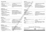
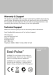
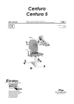
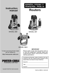
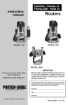
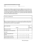
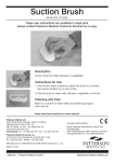
XV. 18-Month Warranty
Sammons Preston Rolyan warrants that the TM-300 Traction Device is free from defects in material and
workmanship. This warranty shall remain in effect for 18 months from the date of original consumer purchase
of the product. If the product fails to function during the warranty period due to a defect in material or
workmanship, Sammons Preston Rolyan or the selling dealer will repair or replace the unit without charge
within a 30-day period from the date on which the unit is returned to Sammons Preston Rolyan or the selling
dealer.
This warranty does not cover the following:
• Replacement parts or labor furnished by anyone other than Sammons Preston Rolyan, the selling dealer,
or any approved service agent.
• Any failure of the unit during the warranty period if the failure is not caused by a defect in material or
workmanship or if the failure is caused by unreasonable use, including the failure to provide reasonable
and necessary maintenance.
This warranty gives the purchaser specific legal rights, and the purchaser may have other rights, which vary
from state to state.
Sammons Preston Rolyan is not liable for incidental or consequential damage to property or business.
To obtain service under this warranty, contact Sammons Preston Rolyan or the selling dealer.
Sammons Preston Rolyan does not authorize any person or dealer to create for it any other
obligations or liabilities in connection with the sale of the TM-300 Traction Devices. Any representation
or agreement not contained in this warranty shall be void.
Designs and specifications are subject to change without notification.
Authorized European Representative
Sammons Preston Rolyan
An AbilityOne Company
4 Sammons Court
Bolingbrook, IL 60440
Phone: 800-323-5547
Direct Phone: 630-226-1300
Fax: 800-547-4333
Direct Fax: 630-226-1388
Sammons Preston Rolyan
Homecraft
An AbilityOne Company
W68 N158 Evergreen Blvd.
Cedarburg, WI 53012
An AbilityOne Company
Shelley Road, Lowmoor Business Park
Kirkby-In-Ashfield, Nottinghamshire NG17 7ET
United Kingdom
Phone: 1623-726828
Fax: + 44 (0) 1623 755585
© July 2001, Revised 8/01, 10/01, 6/02, 7/04
AbilityOne Corporation
9104.783
12
TM-300 Traction Device
Product No. A501-009
User’s Manual
WARNING:
• Read this manual completely before using the device. Store it near the device so it can be referred to as needed.
CAUTION:
• This traction device should be used only by or under the direction of a qualified healthcare professional.
Warning and Caution Symbols
The following symbols are used to indicate that failure to comply with the instructions could result in injury or
damage to property.
WARNING:
• Failure to comply may result in serious injury or death.
CAUTION:
• Failure to comply may result in injury or damage to property.
Table of Contents
I.
II.
III.
IV.
V.
VI.
VII.
VIII.
IX.
X.
XI.
XII.
XIII.
XIV.
XV.
2
Indications . . . . . . . . .
Contraindications . . . . .
Components . . . . . . . .
Installation . . . . . . . . .
Operating procedures . . .
Instructions for use . . . . .
Operational flowchart . . .
Using stored programs . .
Reset procedures . . . . .
Recalibrating traction force
Error display . . . . . . . .
Troubleshooting . . . . . .
Maintenance and inspection
Specifications . . . . . . .
Warranty . . . . . . . . . .
I. Indications
.
.
.
.
.
.
.
.
.
.
.
.
.
.
.
.
.
.
.
.
.
.
.
.
.
.
.
.
.
.
.
.
.
.
.
.
.
.
.
.
.
.
.
.
.
.
.
.
.
.
.
.
.
.
.
.
.
.
.
.
.
.
.
.
.
.
.
.
.
.
.
.
.
.
.
.
.
.
.
.
.
.
.
.
.
.
.
.
.
.
.
.
.
.
.
.
.
.
.
.
.
.
.
.
.
.
.
.
.
.
.
.
.
.
.
.
.
.
.
.
.
.
.
.
.
.
.
.
.
.
.
.
.
.
.
.
.
.
.
.
.
.
.
.
.
.
.
.
.
.
. 2
. 2
. 3
. 4
. 4
. 7
. 8
. 9
. 9
. 9
.10
.10
.10
.11
.12
• To exert therapeutic pulling forces on the body
• Traction can be used for the following conditions:
—osteoarthritis
—headaches
—herniated discs
—muscle tightness
—joint stiffness
—cervical root compression
II. Contraindications
• Not for use in the presence of the following:
—acute or traumatic injury
—spinal instability
—fracture
—rheumatoid arthritis
—spinal cord compression
—infections and inflammatory diseases
—malignancy
—any condition that might be worsened by movement
III. Components
Hook for spreader bar
Main unit pulley
Numerical keyboard
(“ten keys”)
LCD display
Stop key
Function keys
Start key
Clear key
Front view of TM-300 Traction Device
LCD control knob
Connector for patient switch
Power source connector
Force unit of measure
(kg / lb.) switch
Power switch
Fuses
Rear view of TM-300 Traction Device
3
IV. Installation
WARNING:
• Do not operate the unit in areas where flammable materials
are present. Avoid materials such as oxygen, nitrous oxide,
air mixed with flammable anesthetic gas, disinfectants, and
cleaning solutions.
• Turn off the unit immediately if you notice smoke, unusual
noise, or other abnormalities. Failure to do so may result in
electric shock or fire. Consult an authorized representative
for repair; do not attempt to repair the unit yourself.
• Do not disassemble or modify the unit. Doing so may cause
injury, electric shock, or fire.
• Do not use power sources other than those specified. Doing
so may result in electric shock or fire.
• Do not touch the power plug with wet hands. Doing so may
result in electric shock.
• Turn off the power immediately if foreign materials or liquids
penetrate the unit. Consult an authorized representative for
service.
• Inspect the power cord frequently and do not use the unit if
the cord is damaged. Doing so may result in electric shock
or fire.
• Observe the following in regard to the power cord:
—Do not modify the cord.
—Do not place heavy objects on the cord.
—Do not bend, twist, or forcefully pull the cord.
—Hold the plug, not the cord, when connecting or
disconnecting it.
—Do not connect the plug if dirt, dust, and other foreign
materials are adhered to it.
—Be sure to insert the plug fully into the outlet.
• Do not connect the plug to an outlet with multiple wiring.
Doing so may cause the cord to become overheated,
resulting in fire.
CAUTION:
• Install the unit on a firm, level surface.
• The unit should be kept between 10 and 40°C / 50° and
105°F, with relative humidity between 30 and 80%.
• Do not install the unit in the following locations:
—Within 1.5 m / 5 ft. of equipment that generates
electromagnetic waves.
—Near an electrical device that may be affected by an
electromagnetic field. Doing so may interfere with the
performance of and may cause damage to that device.
—In areas subject to direct sunlight, dust, dirt, or extreme
changes in temperature or humidity.
—In places where the unit may become wet or damp.
—In areas where chemical agents are stored or gas is
generated.
—Near fire.
Installing the Unit
1. When mounting the unit on a traction table, use four
hexagonal bolts. The bottom plate of the unit has four holes
for the bolts. Align the holes of the unit with those of the
mounting plate on the traction table. Insert the bolts and
tighten them to hold the unit in place.
CAUTION:
• Never use bolts other than the ones specified. Substituting
other bolts may cause injury or damage to the unit.
2. To connect the patient switch to the back of the unit, insert
the plug on the switch into the connector for patient switch
(labeled on page 3) and turn the ring to attach it firmly.
3. Insert the accessory power cable into the power source
socket on the unit and then insert the plug into the power
outlet.
4. When the power switch is turned on, the window displays the
message, “Set parameters.” Check the traction force unit of
measure (kilograms or pounds). To change it, adjust the slide
switch on the back of the unit. Note that stored programs are
erased when the unit powers up if the force unit of measure
(kg / lb.) has been changed.
5. The brightness of the LCD screen can be adjusted by turning
the LCD control knob on the back of the unit.
V. Operating Procedures
LCD Display
The unit uses an LCD display for setting treatment parameters
and displaying status, as well as other functions. Explanations of
window images that occur during routine operations are given
below. The relation among the windows is illustrated in the
Operational Flowchart on page 8.
A. Windows for setting treatment parameters
When the power is turned on, the unit automatically performs
an initial self-diagnosis. Then it displays the “Set parameters”
window.
1. Treatment parameter setting window
Set parameters
1
Program No.
MAX
FORCE
HIGH
FORCE
4
0
9 0 kg
LOW
FORCE
HIGH
FORCE
LOW
FORCE
HOLD
TIME
REST
TIME
SPEED
TREAT
TIME
HOLD
TIME
REST
TIME
SAVE
1 5 kg
1 5 kg
1 0 sec.
5 sec.
1
1 0 min
PRGM.
LIST
SPEED
TREAT
TIME
SAVE
AS
MODE
SELECT
2. Traction mode designation window
C. Windows that appear during operation
1. In-operation window
In Operation
1
Select a traction mode
1
2
3
4
5
6
FORCE
HOLD
TIME
TREAT
TIME
7
8
5 kg
8 sec.
1 0 min
HIGH
FORCE
LOW
FORCE
HOLD
TIME
REST
TIME
SPEED
TREAT
TIME
HIGH
FORCE
5 kg
0 kg
2 0 sec.
1 9 sec.
1
1 0 min
LOW
FORCE
TREAT
TIME
9
PROGRAM LIST
3. Program list window
2. Treatment completion window
PROGRAM LIST
No. MODE
HIGH
FORCE
LOW
FORCE
HOLD
TIME
REST
TIME
SPEED
PAGE
TREAT
TIME
01
02
03
04
05
06
07
08
09
10
DEL
D. Window indicating errors
See Section XI on page 10 for an explanation of error
messages.
MODE
SELECT
Traction Modes
OK
The unit can provide eight traction modes, including intermittent
and static modes. The traction patterns illustrated below can be
chosen in the window for designating the traction mode.
Modes 1–3
Intermittent traction, all with 0 kg / 0 lb. low force and the option of
setting the high force.
• Mode 1 offers a ramp up to the high force and a ramp down
to the zero low force.
B. Windows indicating analysis
Two windows are available:
1. System check underway
2. Traction force over 18 kg / 40 lb.
1
>18kg (40lbs)
• Mode 2 offers a step progression to the high force and a
ramp down to the zero low force. The high force is achieved in
increments of one-fourth of the high force.
A high force of over
18kg (40lbs) has been
set.
(1)
If acceptable, press OK key.
(2)
If not, set 18kg force or less
using ten keys and press OK
key.
25
2
OK
kg
• Mode 3 offers a step progression to the high force and down
to the zero low force, both in increments of one-fourth of the
high force.
3
5
Modes 4–6
Intermittent traction, with the option of setting the low force as
well as the high force.
• Mode 4 offers a ramp up to the high force and a ramp down
to the low force.
4
• Mode 5 offers a step progression to the high force and a
ramp down to the low force. The high force is achieved in
increments of one-fourth of the high force.
5
• Mode 6 offers a step progression to the high force and down
to the low force, both in increments of one-fourth of the high
force.
6
Numeric values are input through the numerical keyboard.
Two-digit numbers are accepted instantly, while single-digit
numbers are accepted after a slight pause.
1. Setting a high force (range: 1–90 kg / 1–198 lb.)
1. Press the High Force key.
2. Use the keyboard to input a numerical value within the
range (values outside the range are not accepted).
2. Setting a low force (range: 0–89 kg / 0–197 lb.)
(Traction modes 1–3 do not allow a low force to be set; the
pre-set is zero.)
1. Press the Low Force key.
2. Use the keyboard to input a numerical value within the
range (values outside the range are not accepted).
3. Setting a hold time (range: 0–99 seconds)
(Hold time can be set only for traction modes 1–6,
intermittent.)
1. Press the Hold Time key.
2. Use the keyboard to input a numerical value within the
range (values outside the range are not accepted).
4. Setting a rest time (range: 0–99 seconds)
(Rest time can be set only for traction modes 1–6,
intermittent.)
1. Press the Rest Time key.
2. Use the keyboard to input a numerical value within the
range (values outside the range are not accepted).
5. Setting a treatment time (range: 1–99 minutes)
1. Press the Treatment Time key.
2. Use the keyboard to input a numerical value within the
range (values outside the range are not accepted).
Modes 7–8
Static traction.
6. Setting a speed
• Mode 7 offers a ramp up to the high force, which is
maintained for the entire treatment time.
7
• Mode 8 offers a step progression to the high force in
increments of one-fourth of the high force, which is
maintained for the entire treatment time.
8
Procedures
Procedures are described in the sequence of operation.
A. Inputting treatment parameters
The six function keys (
) along the bottom of the window
are for inputting treatment parameters. When a key is
pressed, the display changes and the unit makes one click
sound. If a key that is incompatible with the traction mode is
pressed, the instruction is not accepted and an error is
indicated by two click sounds.
6
Traction modes 1, 4 and 7 offer only ramp to and from
(if applicable) the high force, and only the standard speed
is available. “1” (applying to the rise) automatically appears
in the window. For traction modes 2, 3, 5, 6 and 8
(offering steps to and from [if applicable] the high force),
the time held on each step can be set. The following
speeds are available:
1. 1/2 speed: Press the Speed key and “2.”
2. 1/3 speed: Press the Speed key and “3.”
7. Changing the traction mode
The traction mode can be changed in the appropriate
window, as follows:
1. Press the Mode Select key to bring up the window.
2. Use the keyboard to input the desired mode number.
The selected mode display reverses, and the window
for setting parameters appears.
Note: The program number is shown as “0” when the
window changes from the traction mode window to the
parameter setting window.
8. Retrieving the list of stored programs
Frequently used programs for specific treatments or
patients can be stored in the memory, reducing time and
effort by avoiding the manual setting of treatment
parameters. For more information, see Section VIII on
page 9.
1. Press the Program List key.
9. Storing treatment programs
Note that program number “0” cannot be used.
Three methods of registration are available:
1. To register a program as the lowest unused number in
the program list, simply press the Save As key.
2. To assign a program number, press the Save As key
and, within two seconds, use the keyboard to input the
desired number.
3. To store the program again using the same number,
simply press the Save key.
B. The 18 kg / 40 lb. force check window
Preparation
Set the traction cable correctly. Check the following:
• The pulley for adjusting the traction angle must be firmly
attached to the pole.
• The pulley must be set in the correct direction.
• The cable must not be twisted, and there must not be cracks
in the coating.
The small roller helps prevent the cable from breaking if the pulley
is set in the wrong direction. Do not use this roller to guide the
cable. Correct use of the pulley is illustrated below.
This window appears when the traction force exceeds
18 kg / 40 lb.
1. Press the OK key if the setting is appropriate.
2. To set a value less than 18 kg / 40 lb., use the keyboard to
input the value and press the OK key.
C. The in-operation window
During treatment, this window is displayed continuously. Hold
time and rest time are counted down in intervals of one
second. Treatment time is counted down in intervals of one
minute and, during the last minute, in intervals of one second.
Changes in high force and low force are displayed as
numerical values and bar graphs. The bar graph uses the
initial traction force as 100%.
Treatment parameters can be changed during therapy. High
and low forces and treatment time can be changed without
interrupting treatment as follows:
1. Press the appropriate key and use the keyboard to input a
new value.
VI. Instructions for Use
Correct
Incorrect
Treatment
1. When the unit is turned on, the parameters of the most recent
treatment are displayed. To change the parameters, press the
appropriate keys and use the keyboard to input a new value.
Note: When changing the traction mode, the parameters that
are programmed into the unit (program number 0) are
displayed in the window used for setting treatment
parameters.
2. Press the Start key. The message “System check underway”
is displayed.
3. The window display changes to “>18 kg / 40 lb.” This window
appears when the traction force is pre-set to 19 kg / 41 lb. or
higher.
1. Press the OK key to accept the traction force setting.
2. To change the traction force, use the keyboard to input a
new value and press the OK key.
Before Using the Unit
Before using the unit, observe the following:
• Designate a staff member to be responsible for the unit.
• Do not allow patients to operate the unit.
CAUTION:
• Do not operate the unit without pulling out the traction
cable. Doing so may cause damage or malfunction.
• Never operate the unit without the remote patient switch. (If
the remote patient switch is not connected, an E2 error is
displayed; refer to Section XI on page 10.)
• Be sure the patient has the remote switch and has been
trained on how to stop the unit in case of emergency.
• Do not touch the inner pins of the connector for the remote
patient switch.
4. The message “In operation” appears and treatment begins.
5. When the set treatment time has elapsed, the buzzer sounds
six times, the traction force is released to 0 kg / 0 lb., and the
message “Treatment Is Over” is displayed. In five seconds,
the window for setting treatment parameters appears.
Using the remote patient switch during treatment
When the patient presses the patient switch during treatment, the
traction cable loosens immediately, the traction force is released
to 0 kg / 0 lb., and the equipment ceases operation. The buzzer
sounds 30 times. The countdown stops and the treatment window
is suspended, waiting for further instructions.
1. To continue treatment, press the Start key.
2. To terminate treatment, press the Stop key or the remote
patient switch.
Terminating treatment
To stop treatment, press the Stop key. The traction cable loosens
immediately and the traction force is released to 0 kg / 0 lb., the
equipment ceases operation, and the window for setting
parameters appears
7
VII. Operational Flowchart
Set parameters
1
0
Program No.
MAX
FORCE
HIGH
FORCE
9 0 kg
LOW
FORCE
HIGH
FORCE
LOW
FORCE
HOLD
TIME
REST
TIME
SPEED
TREAT
TIME
HOLD
TIME
PRGM.
LIST
SPEED
TREAT
TIME
REST
TIME
Select a traction mode
SAVE
1 5 kg
1 5 kg
1 0 sec.
5 sec.
1
1 0 min
>18kg (40lb.)
(1) If acceptable, press OK key.
OK
kg
In Operation
FORCE
HOLD
TIME
TREAT
TIME
5 kg
8 sec.
1 0 min
HIGH
FORCE
LOW
FORCE
HOLD
TIME
REST
TIME
SPEED
TREAT
TIME
HIGH
FORCE
5 kg
0 kg
2 0 sec.
1 9 sec.
1
1 0 min
LOW
FORCE
Treatment is over.
The parameter setting window
will appear in five seconds.
8
4
5
6
7
8
TREAT
TIME
9
PROGRAM LIST
01
02
03
04
05
06
07
08
09
10
A high force of over
18kg (40lb.) has been
set.
1
3
PROGRAM LIST
No. MODE
25
2
MODE
SELECT
System check underway
(2) If not, set 18kg force or less
using ten keys and press OK
key.
1
SAVE
AS
HIGH
FORCE
LOW
FORCE
HOLD
TIME
REST
TIME
SPEED
PAGE
TREAT
TIME
DEL
MODE
SELECT
OK
VIII. Using Stored Programs
The program list stores programs that have been defined in the
treatment parameter window. Changes in individual parameters
cannot be made in the program list window. Note that if the unit of
traction force (kg / lb.) is different while the unit powers up than it
was when the programs were stored, the stored programs are
erased.
X. Recalibrating Traction Force
If the traction force reading becomes inaccurate, recalibration is
needed. Simple recalibration can be done at the site of
installation, as follows:
1. Connect a balancer capable of measuring an object of 5 kg /
11 lb. or more. Connect the balance to the hook of the
traction cable as shown.
A. Recalling the program list
In the window for setting treatment parameters or the window
for choosing the traction mode, press the Program List key.
B. Designating the program number
Use the keyboard to enter the desired number. The
designated program number column reverses. Then, press
the OK key to display the treatment parameters of the
designated program.
• To cancel the program number just entered, press the Clear
key.
• To change the designated program number, use the
keyboard to enter the new number.
• Only the program numbers that appear on the screen can
be used. Press the Page key to access additional numbers.
C. Changing the page of the program list
The program list has two pages. To change pages, press the
Page key.
D. Deleting a stored program
Use the keyboard to enter the program number to be deleted
and press the Del key.
E. Changing to the window for selecting a traction
mode
To access the window for selecting a mode, press the Mode
Select key.
2. Turn the power on and wait for the treatment parameters
window to appear.
3. Press the Stop key and, within five seconds, press the
numeric keys 1, 4 and 7 (in that order). The window for
calibrating traction force appears.
Calibration of Traction Force
Calibration for 5kg (11lbs)
(1) Conti nue pres s i ng " 8" k ey unti l
s pri ng s c al e i ndi c ates 5k g.
(2) P res s " 5" k ey .
Note
If traction force is above
5kg (11lbs), press "2" key to
reduce force.
IX. Reset Procedures
If it becomes impossible to perform the operations in a window,
reset the unit as follows:
1. Turn off the power.
2. Hold down the Clear key and turn on the power.
Resetting the unit returns it to the window for setting treatment
parameters.
4. Follow the instructions in the window to perform recalibration.
The message “Calibration has been completed” indicates
recalibration is complete.
9
XI. Error Display
The unit performs a self-test at various stages: when the power is
turned on, at the beginning of treatment, and at each step of
treatment. If an error occurs as a result of improper handling or
malfunction of the equipment, an error message is displayed.
XII. Troubleshooting
Check the following points before contacting an authorized
service representative.
1. Symptom
Cause
ERROR
Solution
E2:The patient switch is either off
or disconnected.
E3:Inoperable.
Machine needs repair.
Contact dealer for repair.
2. Symptom
Cause
Solution
A. An E2 error
This error is related to the remote patient switch. Proceed as
follows:
3. Symptom
Solution
1. Ensure that the patient switch is connected to the
equipment. If it is not, turn off the power, connect the
remote switch, and turn the power on again.
2. If the remote patient switch was pressed while the unit was
performing an initial self-test:
• Press the Start key to continue operation.
• Press the Stop key to go to the window for setting
treatment parameters.
3. If the remote patient switch was pressed during treatment:
• Press the Start key to resume treatment.
• Press the Stop key to terminate treatment.
B. An E3 error
This error indicates the unit is inoperative due to machine
trouble. Turn off the power and contact the Sammons Preston
Rolyan customer service department, a sales representative
or an authorized equipment dealer for service.
Traction cable cannot be pulled out during
installation.
Clutch unit might not have been triggered prior
to transporting the unit.
1. Turn on the power and set the traction force
to 5 kg / 11 lb. or lower.
2. Start operation.
3. Press the Stop key to halt operation.
4. Pull the traction cable out.
All data of stored programs have been lost.
Data were erased by turning the power on after
the force unit of measure (kg / lb.) switch was
changed. This feature offers protection against
excessive traction force as a result of unit of
measure conversion.
Re-enter data.
No display when power turned on.
Use the LCD control knob at the rear of the unit
to adjust the brightness of LCD screen.
or
Check the two fuses at the rear of the unit; if
they are burned out, replace them with
125VF2A Midget type fuses.
XIII. Maintenance and Inspection
Cleaning
Use a dry cloth to wipe the unit to clean it. To avoid discoloration,
do not use hot water or chemical substances such as paint
thinner, gasoline, paraffin oil and cleanser. If necessary, the
equipment can be wiped with lukewarm water or detergent. It
must be dried thoroughly before reuse.
1. If the unit has not been used for some time, check it to make
sure it functions properly before use.
2. The unit must be checked and serviced by an authorized
service technician once a year.
3. If the traction cable does not wind smoothly into the unit
because of twisting or damage to the nylon coating, contact
an authorized service technician for service.
4. Traction adjustment is easily made, and it can be carried out
on the site without consulting an authorized representative—
see Section X on page 9. If the traction force seems
inadequate even after adjusting it, contact an authorized
service technician for service.
10
XIV. Specifications
Rated voltage and frequency
Power consumption . . . . .
Display . . . . . . . . . . . .
Data input . . . . . . . . . .
Traction force display . . . .
High force range . . . . . . .
Low force range . . . . . . .
Hold time range . . . . . . .
Rest time range . . . . . . .
Traction speed . . . . . . . .
Treatment time range . . . .
Traction modes . . . . . . .
Program memory . . . . . .
Mode of operation . . . . . .
.
.
.
.
.
.
.
.
.
.
.
.
.
.
.
.
.
.
.
.
.
.
.
.
.
.
.
.
.
.
.
.
.
.
.
.
.
.
.
.
.
.
.
.
.
.
.
.
.
.
.
.
.
.
.
.
.
.
.
.
.
.
.
.
.
.
.
.
.
.
.
.
.
.
.
.
.
.
.
.
.
.
.
.
.
.
.
.
.
.
.
.
.
.
.
.
.
.
.
.
.
.
.
.
.
.
.
.
.
.
.
.
.AC 120V, 60Hz
.70 VA
.LCS, 121 x 92 mm, 320 x 240 dots
.Ten-key input
.kg or lb.
.1–90 kg (1–198 lb.)
.0–89 kg (0–197 lb.)
.0–99 seconds
.0–99 seconds
.standard, 1/2 or 1/3
.Intermittent: 1–99 minutes; Static: 1–99 minutes
.8 modes
.20 programs
.Continuous operation
Size . . . . . . . . . . . . . . . . . . . . . .260 mm wide x 330 mm deep x 170 mm high
Weight . . . . . . . . . . . . . . . . . . . . .12 kg
Fuse . . . . . . . . . . . . . . . . . . . . . .125VF2A
Conformity . . . . . . . . . . . . . . . .
Safety class . . . . . . . . . . . . . . .
Type of protection against electric shock
Degree of protection against harmful
ingress of water . . . . . . . . . . .
Risk of explosion . . . . . . . . . . . .
. . .CE (MDD)
. . .Type B
. . .Class I
. . .0
. . .Equipment not suitable for use in the presence of a flammable anesthetic
mixture with air or with oxygen or nitrous oxide
Disposal . . . . . . . . . . . . . . . . . . . .The equipment, disposal, waste and residue should be scrapped and
recycled in accordance with local law to reduce the environmental effect.
Operation environment
Ambient temperature . . . . . . . . . . . . .10 to 40°C
Relative humidity . . . . . . . . . . . . . . .30 to 85%
Atmospheric pressure . . . . . . . . . . . . .70 to 106 kPa
Storage and transport environment
Ambient temperature . . . . . . . . . . . . .–10 to 60°C
Relative humidity . . . . . . . . . . . . . . .30 to 90%
Atmospheric pressure . . . . . . . . . . . . .70 to 106 kPa
Safety features
•
•
•
•
•
Remote patient switch
Automatic halting of traction and traction force release in emergencies
Upper limit setting of high traction force
System to check traction of 18 kg / 40 lb. or higher force
Automatic self-diagnostic function
Other features
•
•
•
•
Automatic traction force compensation
Retention in memory of previous and interrupted treatment data
Display of error contents and solutions
Display of procedures for traction force calibration
11