1
K3129-1V1 7/98
FA245RF
Keypad/Transceiver
INSTALLATION INSTRUCTIONS
For use with QED and hardwired control panels ONLY!
General Information
The FA245RF Keypad/Transceiver is a combination unit. It replaces a FA245KP Fixed Addressable Keypad,
5881/5882M RF Receiver, and a 5800TM Transmitter Module. It also contains a normally-open relay output. The
FA245RF may be used on any QED or hardwired only control panel that supports the FA245KP Keypad (i.e., FA142C,
FA162C, FA1220C, FA1220CV, FA1340C, FA110C, FA120C, FA1200C).
Wireless Setup Considerations
There are 3 major elements involved in setting up the FA245RF. They are:
1. Wireless Keys (may be used as either System keys or Local keys).
2. RF Receiver (may be used as either a System receiver or a Local receiver).
3. House ID (programmed to use either the System’s House ID or the FA245RF’s House ID).
Understanding how these 3 elements are programmed is important for using the FA245RF. An application guide
following the explanations outlines the programming of each element for various installations.
1.
2.
Wireless Keys:
•
These are button-type transmitters (i.e., 5804).
•
They may be set up as System keys or Local
keys.
•
System keys are enrolled into the QED
supported control panel.
•
Local keys are enrolled directly into the
FA245RF and are not supervised for low
battery conditions.
•
Local keys DO NOT occupy any zones
supported by the control panel.
•
The FA245RF is shipped with default settings
for the functions of the wireless keys. See the
Programming Local Wireless Keys section for
the default settings.
Enrolling the keys directly into the FA245RF would
be necessary only in the following circumstances:
•
When using more than the maximum number
of transmitters supported by the control panel.
•
When used on a hardwired control panel.
In all other cases, use wireless keys as System keys
(enroll them into the QED supported control panel).
RF Receiver:
•
The built-in 5881M/5882M Receiver may be
used on a QED supported control as either a
System receiver or a Local receiver.
•
A System receiver passes signals from
transmitters programmed into the control
panel to the control panel.
•
A System receiver passes signals from RF
keypads to the control panel as regular 5800
signal data.
•
A Local receiver passes signals from RF
keypads to the control as console key data (as
though keys were pressed on a hardwired
keypad).
•
When used as a System receiver, it supports a
maximum of 16 transmitters.
•
The receiver and wireless keys have a nominal
range of 200’.
Programming the receiver as Local would be
necessary only in the following circumstances:
•
When using more than the number of
transmitters AND the number of receivers
supported by the control panel.
•
When using multiple wireless keypads to
control (arm/disarm, etc.) different partitions.
•
When used on a hardwired control panel.
NOTES:
a) When used as a System receiver, do not exceed
the number of receivers the control panel
supports.
b) When used as a System receiver, wireless keys
may still be used as Local keys.
3.
House ID Source:
House ID source option determines which House ID the FA245RF will use for wireless keypad operation and for
transmitting status indications to bi-directional devices. Programming this option is only necessary if you are using
wireless keypads (5827) and/or bi-directional devices (i.e., 5827BD, 5804BD).
•
Program the source as System, to use the
control panel’s House ID.
•
When using RF keypads on more than one
partition.
•
Program the source as Local to use the House
ID programmed into the FA245RF.
•
When used on a hardwired control panel.
NOTES:
Programming the source as Local would be necessary in
the following applications:
•
a) If using bi-directional devices, be sure to enable
the transmitter module in the FA245RF.
When using bi-directional (i.e.,5804BD,
5827BD) to get status from more than one
partition.
b) If the House ID source is System, and more
than one FA245RF is being used, make sure
only one FA245RF has the transmitter module
enabled.
FA245RF Application Guide
Below is a guide that outlines the possible applications for the FA245RF. There are 3 application questions you will
need to answer in the guide below.
Application Questions:
Are you using
RF keys
beyond
system’s
capacity?
RF
receivers
beyond
system’s
capacity?
Control Panel
Program Wireless Keys
As
RF keypads
and/or Bidirectional
devices on
more than 1
partition?
Program
RF Receiver
& House ID
Source*** As
N/A
N/A
N/A
FA110C, FA120C, FA1200C,
Local
Local [0]
FA142C
Use System Application Programming
NO
NO
N/A
YES
NO
N/A
Local
System [1]
YES
YES
N/A
Local
Local [0]
NO
NO
NO
YES
NO
NO
Local
System [1]
Use System Application Programming
FA162C
YES
YES
NO
Local
Local [0]
NO
YES
YES*
System
Local [0]
YES
YES
YES*
Local
Local [0]
NO
NO
NO**
YES
NO
NO**
YES
YES
NO**
Local
Local [0]
NO
YES
YES
System
Local [0]
YES
YES
YES
Local
Local [0]
Use System Application Programming
FA1220C,FA1220CV,
FA1340C
Local
System [1]
* Two FA245RFs are needed for this application. One connected to partition 1’s keypad terminals and one connected to partition 2’s.
** If using an RF keypad on only one partition, the FA245RF’s partition assignment must match the partition in field 1*48.
***If set for Local on a partition control, the FA245RF’s partition assignment must match the partition of BD device.
FA245RF Additional Features
•
•
•
2
Supplied with factory default settings. See the
Display/Description Chart for the default values.
See the Programming section for the procedure to
default the FA245RF.
Contains a 5800TM Transmitter Module, which
sends status signals (Armed, Ready, etc.), to bidirection units such as 5804BD and 5827BD.
House ID programmable to 00-31.
•
Receiver address programmable to 00-30 (no DIP
switches).
•
Contains a relay output that can operate in
conjunction with the RF receiver (e.g., trip a garage
door opener, control low voltage lighting).
•
Has a mode that allows the user to enable and
disable individual wireless keys.
This is
particularly useful if a user accidentally loses a
wireless key.
FA245RF Installation
1.
Remove the case back by pushing down the 2
snaps along the FA245RF’s upper edge and pulling
the case apart.
2.
Route the wiring from the control panel through
the opening in the case back. (See the control
panel’s instructions for proper wire run lengths).
3.
Mount the case back directly to a wall or
electrical gang box. Do not use the center screw
hole of the top mounting holes.
4.
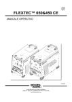
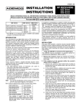
Plug the supplied connector with the flying
leads into the FA245RF’s PC board and splice the
panel wiring to it. (See Figure 2 for wiring
connections).
5.
6.
Reattach the keypad to its case back.
7.
Remove the clear protective films from the
LCD display and keypad labels.
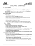
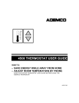
YELLOW
NO CONNECTION
RED
BLACK
GREEN
RELAY
N.O.
BACK OF KEYPAD
(WITH COVER REMOVED)
Connect the wires for the relay output (if
being used) to the terminals on the FA245RF’s PC
board (See Figure 2 for wiring connections).
Figure 2: FA245RF Wiring Connections
1. Do not mount a transmitter closer than 36” from the FA245RF, or improper operation of the transmitter may
result.
2. The ARMED and READY LEDs will flicker while the unit is powered. This is most noticeable while the LEDs
are in the off state (disarmed and not ready). This is normal and will not affect any operation of the
FA245RF.
FA245RF Programming
Entering Program Mode
Press the 1 and 3 keys simultaneously for a few seconds within 30 seconds of applying power to the FA245RF. The
keypad will beep 3 times, and 2 dashes and 2 zeroes will flash alternately in the upper left-hand corner of the display. If
any other numbers or letters are flashing in the display, press the [✳] key.
Enter a Program Option (e.g., (1) Keypad Address) to program the options of the FA245RF. Press [0] to enter User
Mode. See the User Guide for the purpose of this mode.
While in the program mode, the [✳] key stores the information and moves you to the next prompt. The keypad will beep
twice. The [#] key erases the information and moves you back so you may enter the correct information.
The FA245RF is shipped with a set of pre-programmed default values. If needed, the unit may be set back to these
values. See Defaulting the FA245RF on page 7 for the procedure.
Two Programming Methods of the FA245RF
• System:
•Local:
When using the FA245RF in place of a stand-alone 5881/5882 RF Receiver.
For all other applications.
1. System Application Programming
Program Option/
Description
Display
Values
1 Keypad
Address
cA
01-31 Default = 31
2 Receiver
Address
rA
00-30 Default = 00
4 House ID
Source
hS
1=System, 0=Local
Default = 1
6 Receiver
r-
1=System, 0=Local
Default = 1
Enter 1. The display will alternately flash “cA” and a 2-digit
number. Enter the 2-digit keypad address. Press the [✳] key to
continue.
Enter 2. The display will alternately flash “rA” and a 2-digit
number. Enter the 2-digit address for the receiver. Press the [✳]
key to continue.
Leave set to the default value (1) System. Press the [✳] key to
continue.
Leave set to the default value (1) System.
Note: Make sure the number of receivers set for System (1) does
not exceed the capacity of the control panel.
Press the [✳] key to continue.
3
Program Option/
Description
7 Transmitter
Module
Display
tE
Values
1=Enable, 0=Disable
Default = 1
Enter 7. The display will alternately flash “tE” and a digit.
Enter 0 (disabled) or 1 (enabled).
Note: The House ID in the control MUST match the House ID
programmed in the wireless keypad and the bi-directional unit.
Note: If more than one FA245RF is used, make sure only one has
the Transmitter Module enabled.
Press the [✳] key twice to exit the FA245RF Program Mode.
This is all the FA245RF programming necessary for this application. If the display takes a long time to show the System
status (“READY” or “NOT READY”), go back into program mode by pressing the 1 & 3 keys at the same time, then press
[1] and verify the keypad address.
2. Local Application Programming
Use this programming section if your application requires any of the elements (wireless keys, RF receiver, or House ID
source), of the FA245RF to be set as Local. Refer to the FA245RF Application Guide on page 2 for installations that
require these settings.
The programming section is divided into two parts. The first is Programming the Keypad, Receiver, and the Transmitter
Module of the FA245RF. The second part is Programming Local Wireless Keys into the FA245RF.
PROGRAMMING THE KEYPAD, RECEIVER AND TRANSMITTER MODULE OF THE FA245RF
Program Option/
Description
Display
Values
1 Keypad
Address
cA
01-31
Default = 31
2 Receiver
Address
rA
00-30
Default = 00
3 House ID
hI
00-31
Default = 10
4 House ID
Source
hS
1=System
0=Local
Default = 1
4
Enter 1 to program the Keypad Address. The display will alternately
flash “cA” and a 2-digit number. Enter the 2-digit keypad address.
Note: Control panels in the FA142C and FA162C families can only use
keypad address 31. Control panels in the FA1220CV family use keypad
addresses 01-15; the FA1340C family uses keypad addresses 01-30.
Press the [✳] key to continue.
Enter 2 to program the Receiver Address. The display will alternately
flash “rA” and a 2-digit number. Enter the 2-digit address for the
receiver.
Note: Control panels in the FA142C and FA162C families can only use
receiver address 00. Control panels in the FA1220CV family use receiver
addresses 01-15; the FA1340C family uses receiver addresses 01-30.
Press the [✳] key to continue.
Enter 3 to program the House ID. The display will alternately flash “hl”
and a 2-digit number. Enter the House ID for the FA245RF.
Note: The House ID is necessary only if a wireless keypad and/or a bidirectional unit are used and the House ID source is set for Local.
Note: The House ID entered here MUST match the House ID
programmed in the wireless keypad and the bi-directional unit.
Press the [✳] key to continue.
Enter 4 to program the House ID Source. The display will alternately
flash “hS” and a number. Enter 1 (System) to use the control panel’s
House ID. Enter 0 (Local) to use the House ID programmed into the
FA245RF (Program Option 3).
Note: The House ID is necessary only if a wireless keypad and/or a bidirectional unit are used.
Note: If the House ID Source is System (1), the wireless keypad and the
bi-directional units MUST match the House ID programmed into the
control panel.
Note: If the House ID Source is Local (0), the wireless keypad and the
bi-directional units MUST match the House ID programmed into the
FA245RF.
Press the [✳] key to continue.
Program Option/
Description
Display
Values
6 Receiver
r-
1=System
0=Local
Default = 1
7 Transmitter
Module
tE
1=Enable
0=Disable
Default = 1
Enter 6 to program the Receiver. The display will flash “r-” and a digit
alternately. Enter 0 (Local) or 1 (System).
Note: The receiver should be set as “Local” only in the following
circumstances:
•
When using more than the number of wireless zones AND the
number of receivers supported by the QED control panel.
• When using multiple wireless keypads to control (arm/disarm, etc.)
different partitions.
• When using on a control that does not support 5800 Series wireless.
Note: If more than one FA245RF is used, be sure that the number of
receivers set for System (1) does not exceed the capacity of the QED
control panel.
Note: If the receiver is set for System, wireless keys may still be used as
Local keys.
Press the [✳] key to continue.
Enter 7 to program the Transmitter Module. The display will
alternately flash “tE” and a digit. Enter 0 (disabled) or 1 (enabled).
Note: When enabled, the transmitter module will send status signals
(Armed, Ready, etc.) to bi-directional units such as the 5804BD and the
5827BD.
Note: If the House ID source is Local, the House ID entered in the
FA245RF MUST match the House ID programmed in the wireless
keypad and the bi-directional unit. If the House ID source is System, the
House ID in the control MUST match the House ID programmed in the
wireless keypad and the bi-directional unit.
Note: If the House ID source is System and more than one FA245RF is
used, make sure only one has the Transmitter Module enabled.
Press the [✳] key to continue.
LOCAL WIRELESS KEYS PROGRAMMING
Programming this section is necessary only if you plan to use wireless keys beyond the QED control panel’s capacity,
or on a system that does not support 5800 Series wireless. Refer to the FA245RF Application Guide on page 2 for
installations that require these settings.
1.
The FA245RF is supplied with default settings for the functions of the wireless keys. See page 6 for the
default settings.
2.
If at any time during the programming of the wireless keys, you make a wrong entry and want to reprogram
a wireless key, simply press the [✳] key until the Device Number display is showing (d-). Then just enter
the correct information.
3.
Local wireless keys are NOT supervised for low battery conditions.
Program Option/
Description
Display
d-
Choices
1-8
Enter 5 to program the Device Number. The display will flash “d-.”
Enter 1-8 to select the device (wireless key) to program for use in Local
mode only. After the selection is entered, the display will flash “d”
followed by the device number (d1, d2, etc.).
Note: A maximum of 8 wireless keys may be enrolled into the FA245RF.
These wireless keys DO NOT occupy any zones supported by the control.
Sub-Options for Program Option 5 Wireless Key Programming
bL
Press Button Enter 1 to program the Wireless Key’s Serial Number. The display will
Sub Option 1
on Wireless
alternately flash “bL” and blank. This indicates that no wireless key has
Wireless Key
Key
been enrolled yet. If any number is displayed after “bL,” you may erase
Enroll
that number by pressing the [#] key. Press any button on the wireless
key until the FA245RF beeps and the “bL” and the serial number flash
alternately on the display. Button functions will be dealt with later.
Press the [✳] key. The display will be flashing “d” followed by the device
number.
5 Device
Number
5
Sub-Option/
Description
Display
Values
Sub Option 2
4-Digit User
Code
u4
UUUU
(U = User
Code Digit)
Sub Option 3
6-Digit User
Code
u6
UUUUUU
(U = User
Code Digit)
Enter 2 to program the 4-Digit User Code. The display will flash “u4.”
Enter a 4-digit user code that has been assigned for access to the control
panel. The display will momentarily show the 4-digit user code after the
last digit was entered.
Note: Be sure the user code entered is one that is entered in the control
panel. The FA245RF sends the user code to the control panel, whenever
this Local wireless key is pressed.
Press the [✳] key. The display will flash “d” followed by the device
number.
This is for use only with the FA1200C control panel when programmed
for high security mode.
Enter 3 to program the 6-Digit User Code. The display will show “u6.”
Enter a 6-digit user code that has been assigned for access to the control
panel. The display will momentarily show the 6-digit user code after the
last digit was entered.
Note: Be sure the user code entered is one that is entered in the control
panel. The FA245RF sends the user code to the control panel, whenever
this Local wireless key is pressed.
Press the [✳] key. The display will flash “d” followed by the device
number.
Wireless Key Function Chart
Function
Disarming
Arming Away
Arming Stay
Arming Maximum (Away Instant)
Arming Instant
Panic Alarm Produces type of alarm [* & #] programmed in control panel.
Note: Entry for control of 4204 and X-10 relays
depends on the control panel being used.
Manually Start a Relay Action
Manually Stop a Relay Action
Activate Relay as Programmed in Control
Activate Relay as Programmed in Control
Activate Access Control Relay for Partition
n = Device Number to be Controlled
FA142C
#+7
#+8
N/A
N/A
N/A
N/A = Not Applicable
Entry
1
2
3
4
7
# + 99
Control Panel
FA162C
FA1220C, FA1220CV
FA1340C
#+7+n
#+8+n
N/A
N/A
N/A
N/A
N/A
# + 71
# + 72
0
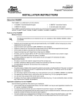
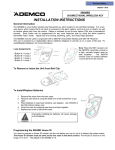
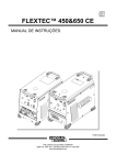
Wireless Keys Default Settings
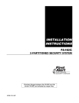
Below are diagrams showing the wireless key’s loops and their default function. Regardless of which wireless
key you use (even if it is one not shown), loops 1-4 are defaulted respectively as follows: Close the FA245RF
relay for 2 seconds; Disarm; Arm Away; and Arm Stay. If you desire to change any functions of the wireless
keys, follow the next two steps.
Loop 2
Disarm
Loop 3
Arm AWAY
Loop 2
Disarm
Loop 4
Arm STAY
Loop 1
Close on-board relay
for 2 seconds
Loop 4
Arm STAY
Loop 3
Arm AWAY
Loop 1
Close on-board relay
for 2 seconds
••
•
••
••
• •• • ••
• • ••
••
5804
6
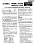
5804BD
SET
HOUSE
CODE
Sub-Option/
Description
Display
Choices
Sub Option 4
Loop Number +
Function
A-
1-4 + YYYY
(Y = Loop
Function)
Sub Option 5
FA245RF Relay
Action
o-
1-4 + Z
(Z = Relay
Action)
Enter 4 to program the Loop Number and its Function. The display will
flash “A-.” Enter the loop number. The display will alternately flash “A”
with the loop number and the current function.
To erase the current entry, press [0] as many times as necessary until
the keypad beeps twice. Again press [0] until the keypad beeps twice.
The display will alternately flash “A” with the loop number and blank.
Enter the function for this wireless key loop (refer to the Wireless Key
Function chart on previous page).
The display will alternately flash “A” with the loop number and the
function you just entered.
Press the [✳] key. The display will flash “A-.” Repeat the procedure
until all loops are programmed for this wireless key.
Press the [✳] key until the display flashes “d” followed by the device
number.
Enter 5 to program the Relay Action. The display will flash “o-.” Enter
the loop number of the wireless key. The display will flash “o” followed
by the loop number. Enter the relay action. There are 5 choices: 0 = no
action; 1 = relay off; 2 = relay on; 3 = relay toggles on & off; 4 = relay
closes for 2 seconds. The display will show “o” and alternately flash the
loop number and the relay action.
Press the [✳] key. The display will show “o-.” Enter the next loop
number and enter the relay action.
When all loops have been programmed for this wireless key, press the
[✳] key. The display will flash “d” followed by the device number.
Repeat steps starting at Program Option 5 until all wireless keys have
been programmed.
Press the [✳] key twice. This will take you back to the main display,
which will alternately flash “oo” and “- -.”
Press the [✳] to exit the FA245RF Program Mode.
Note: If the display takes a long time to show the system status (“READY” or “NOT READY”), go back into program
mode by pressing the 1 & 3 keys at the same time, then press [1] and verify the keypad address.
Defaulting the FA245RF
The FA245RF is shipped with a set of pre-programmed default values. The installer to suit specific needs can change
these default values. To restore the FA245RF’s default values, perform the following procedure:
1.
Enter the program mode. The keypad will alternately flash 00 and 2 dashes.
2.
Press the [9] key. The display will flash EE.
3.
Press the [1] key to restore the default values, or press any other key to exit without restoring the default values.
If [1] was pressed the keypad will beep 3 times and return to alternately flashing 00 and 2 dashes. If any other key was
pressed the keypad will not beep and return to the alternately flashing the 00 and 2 dashes.
4.
Press the [✳] to exit the FA245RF Program Mode.
Specifications
Physical:
4-3/4” H x 5-3/4” W x 1” D (121mm x
146mm x 25.4mm)
Wiring:
Red
Black
Green
Yellow
+12VDC
Ground
Data to Control Panel
Data from Control Panel
Current:
Relay:
Sounder:
Standby
60ma
Transmitting and/or
Relay Activated
120ma
Normally Open, 2A, 28VDC
Piezo-electric (fire alarm is loud pulsing
tone; burglary/audible panic alarm is
continuous tone)
7
FOR DETAILS ON THE LIMITATIONS OF THE ENTIRE ALARM SYSTEM, REFER TO THE INSTALLATION
INSTRUCTIONS FOR THE CONTROL PANEL WITH WHICH THIS DEVICE IS USED.
FCC STATEMENT
This device complies with Part 15 of the FCC rules. Operation is subject to the following two conditions: (1) This device may not cause harmful interference,
and (2) This device must accept any interference received, including interference that may cause undesired operation.
FCC ID.CFS8DLFA245RF
FEDERAL COMMUNICATIONS COMMISSION (FCC) Part 15 STATEMENT
This equipment has been tested to FCC requirements and has been found acceptable for use. The FCC requires the following statement for your information:
This equipment generates and uses radio frequency energy and if not installed and used properly, that is, in strict accordance with the manufacturer's
instructions, may cause interference to radio and television reception. It has been type tested and found to comply with the limits for a Class B computing
device in accordance with the specifications in Part 15 of FCC Rules, which are designed to provide reasonable protection against such interference in a
residential installation. However, there is no guarantee that interference will not occur in a particular installation. If this equipment does cause interference to
radio or television reception, which can be determined by turning the equipment off and on, the user is encouraged to try to correct the interference by one or
more of the following measures:
•
If using an indoor antenna, have a quality outdoor antenna installed.
•
Reorient the receiving antenna until interference is reduced or eliminated.
•
Move the radio or television receiver away from the receiver/control.
•
Move the antenna leads away from any wire runs to the receiver/control.
•
Plug the receiver/control into a different outlet so that it and the radio or television receiver are on different branch circuits.
If necessary, the user should consult the dealer or an experienced radio/television technician for additional suggestions. The user or installer may find the
following booklet prepared by the Federal Communications Commission helpful: "Interference Handbook"
This booklet is available from the U.S. Government Printing Office, Washington, DC 20402.
The user shall not make any changes or modifications to the equipment unless authorized by the Installation Instructions or User's Manual. Unauthorized
changes or modifications could void the user's authority to operate the equipment.
LIMITED WARRANTY
Pittway Corporation, and its divisions, subsidiaries and affiliates ("Seller"), 165 Eileen Way, Syosset, New York 11791,
warrants its First Alert products to be in conformance with its own plans and specifications and to be free from defects in
materials and workmanship under normal use and service for 36 months from the date stamp control on the product or,
for products not having a date stamp, for 30 months from date of original purchase unless the installation instructions or
catalog sets forth a shorter period, in which case the shorter period shall apply. Seller's obligation shall be limited to
repairing or replacing, at its option, free of charge for materials or labor, any product which is proved not in compliance
with Seller's specifications or proves defective in materials or workmanship under normal use and service. Seller shall
have no obligation under this Limited Warranty or otherwise if the product is altered or improperly repaired or serviced
by anyone other than First Alert factory service. For warranty service, return product transportation prepaid, to First
Alert Factory Service, 165 Eileen Way, Syosset, New York 11791.
THERE ARE NO WARRANTIES, EXPRESS OR IMPLIED, OF MERCHANTABILITY, OR FITNESS FOR A PARTICULAR PURPOSE OR OTHERWISE, WHICH EXTEND BEYOND THE DESCRIPTION ON THE FACE HEREOF.
IN NO CASE SHALL SELLER BE LIABLE TO ANYONE FOR ANY CONSEQUENTIAL OR INCIDENTAL DAMAGES
FOR BREACH OF THIS OR ANY OTHER WARRANTY, EXPRESS OR IMPLIED, OR UPON ANY OTHER BASIS OF
LIABILITY WHATSOEVER, EVEN IF THE LOSS OR DAMAGE IS CAUSED BY THE SELLER'S OWN NEGLIGENCE
OR FAULT.
Seller does not represent that the products it sells may not be compromised or circumvented; that the products will
prevent any personal injury or property loss by burglary, robbery, fire or otherwise; or that the products will in all cases
provide adequate warning or protection. Customer understands that a properly installed and maintained alarm may
only reduce the risk of a burglary, robbery, fire or other events occurring without providing an alarm, but it is not
insurance or a guarantee that such will not occur or that there will be no personal injury or property loss as a result.
CONSEQUENTLY, SELLER SHALL HAVE NO LIABILITY FOR ANY PERSONAL INJURY, PROPERTY DAMAGE
OR OTHER LOSS BASED ON A CLAIM THE PRODUCT FAILED TO GIVE WARNING. HOWEVER, IF SELLER IS
HELD LIABLE, WHETHER DIRECTLY OR INDIRECTLY, FOR ANY LOSS OR DAMAGE ARISING UNDER THIS
LIMITED WARRANTY OR OTHERWISE, REGARDLESS OF CAUSE OR ORIGIN, SELLER'S MAXIMUM LIABILITY
SHALL NOT IN ANY CASE EXCEED THE PURCHASE PRICE OF THE PRODUCT, WHICH SHALL BE THE
COMPLETE AND EXCLUSIVE REMEDY AGAINST SELLER. This warranty replaces any previous warranties and is
the only warranty made by Seller on this product. No increase or alteration, written or verbal, of the obligations of this
Limited Warranty is authorized.
Syosset, NY 11791
Copyright 1998 PITTWAY Corporation
¬.9Ul
K3129-1V1 7/98