1
FA245RF Installation
1.
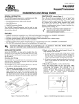
Remove the case back by pushing down the 2
snaps along the FA245RF’s upper edge and pulling
the case apart.
2.
Route the wiring from the control panel through
the opening in the case back. (See the control
panel’s instructions for proper wire run lengths).
3.
Mount the case back directly to a wall or
electrical gang box. Do not use the center screw
hole of the top mounting holes.
4.
Plug the supplied connector with the flying
leads into the FA245RF’s PC board and splice the
panel wiring to it. (See Figure 2 for wiring
connections).
5.
6.
Reattach the keypad to its case back.
7.
Remove the clear protective films from the
LCD display and keypad labels.
YELLOW
NO CONNECTION
RED
BLACK
GREEN
RELAY
N.O.
BACK OF KEYPAD
(WITH COVER REMOVED)
Connect the wires for the relay output (if
being used) to the terminals on the FA245RF’s PC
board (See Figure 2 for wiring connections).
Figure 2: FA245RF Wiring Connections
1. Do not mount a transmitter closer than 36” from the FA245RF, or improper operation of the transmitter may
result.
2. The ARMED and READY LEDs will flicker while the unit is powered. This is most noticeable while the LEDs
are in the off state (disarmed and not ready). This is normal and will not affect any operation of the
FA245RF.
FA245RF Programming
Entering Program Mode
Press the 1 and 3 keys simultaneously for a few seconds within 30 seconds of applying power to the FA245RF. The
keypad will beep 3 times, and 2 dashes and 2 zeroes will flash alternately in the upper left-hand corner of the display. If
any other numbers or letters are flashing in the display, press the [✳] key.
Enter a Program Option (e.g., (1) Keypad Address) to program the options of the FA245RF. Press [0] to enter User
Mode. See the User Guide for the purpose of this mode.
While in the program mode, the [✳] key stores the information and moves you to the next prompt. The keypad will beep
twice. The [#] key erases the information and moves you back so you may enter the correct information.
The FA245RF is shipped with a set of pre-programmed default values. If needed, the unit may be set back to these
values. See Defaulting the FA245RF on page 7 for the procedure.
Two Programming Methods of the FA245RF
• System:
•Local:
When using the FA245RF in place of a stand-alone 5881/5882 RF Receiver.
For all other applications.
1. System Application Programming
Program Option/
Description
Display
Values
1 Keypad
Address
cA
01-31 Default = 31
2 Receiver
Address
rA
00-30 Default = 00
4 House ID
Source
hS
1=System, 0=Local
Default = 1
6 Receiver
r-
1=System, 0=Local
Default = 1
Enter 1. The display will alternately flash “cA” and a 2-digit
number. Enter the 2-digit keypad address. Press the [✳] key to
continue.
Enter 2. The display will alternately flash “rA” and a 2-digit
number. Enter the 2-digit address for the receiver. Press the [✳]
key to continue.
Leave set to the default value (1) System. Press the [✳] key to
continue.
Leave set to the default value (1) System.
Note: Make sure the number of receivers set for System (1) does
not exceed the capacity of the control panel.
Press the [✳] key to continue.
3