1
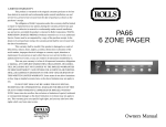
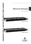
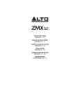
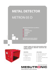
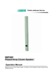
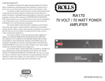
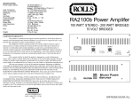
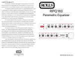
LIMITED WARRANTY
This product is warranted to the original consumer purchaser to be free from
defects in materials and workmanship under normal installation, use and service for a
period of one (1) year from the date of purchase as shown on the purchaser’s receipt.
The obligation of Rolls Corporation under this warranty shall be limited to repair
or replacement (at our option), during the warranty period of any part which proves
defective in material or workmanship under normal installation, use and service, provided
the product is returned to Rolls Corporation, TRANSPORTATION CHARGES PREPAID. Products returned to us or to an authorized Service Center must be accompanied by
a copy of the purchase receipt. In the absence of such purchase receipt, the warranty
period shall be one (1) year from the date of manufacture.
This warranty shall be invalid if the product is damaged as a result of defacement, misuse, abuse, neglect, accident, destruction or alteration of the serial number,
improper electrical voltages or currents, repair, alteration or maintenance by any person or
party other than our own service facility or an authorized Service Center, or any use
violative of instructions furnished by us.
This one-year warranty is in lieu of all expressed warranties, obligations or
liabilities. ANY IMPLIED WARRANTIES, OBLIGATIONS, OR LIABILITIES,
INCLUDING BUT NOT LIMITED TO THE IMPLIED WARRANTIES OF MERCHANTABILITY AND FITNESS FOR A PARTICULAR PURPOSE, SHALL BE
LIMITED IN DURATION TO THE ONE YEAR DURATION OF THIS WRITTEN
LIMITED WARRANTY. Some states do not allow limitations on how long an implied
warranty lasts, so the above limitation may not apply to you.
IN NO EVENT SHALL WE BE LIABLE FOR ANY SPECIAL, INCIDENTAL
OR CONSEQUENTIAL DAMAGES FOR BREACH OF THIS OR ANY OTHER
WARRANTY, EXPRESSED OR IMPLIED, WHATSOEVER. Some states do not allow
the exclusion or limitation of special, incidental or consequential damages so the above
limitation or exclusion may not apply to you. This warranty gives you specific legal
rights, and you may also have other rights which vary from state to state.
RA900
PROFESSIONAL
POWER AMPLIFIER
POWER
CHANNEL A
PROTE
CLIP
SIGNA
POWE
0
ROTECT
10
CHANNEL B
CLIP
IGNAL
OWER
0
ROLLS CORPORATION
SALT LAKE CITY, UTAH
11/99
10
RA900
OWNERS MANUAL
SPECIFICATIONS
Power Output, Stereo:
Bridged:
Input Connectors:
Output Connectors:
Sensitivit y:
THD:
Frequency response:
Hum and Noise:
Power Consumption:
Cooling System:
Transformer:
Size:
Weight:
570 W RMS/ch. 2Ω
410 W RMS/ch. 4 Ω
260 W RMS/ch. 8 Ω
1100 Watts RMS 4 Ω
850 Watts RMS 8 Ω
1/4" TRS balanced and XLR balanced
1/4" and 5-way binding posts
0.9 V rms 0 dB V
<.05% (20Hz - 20 kHz)
@ rated output, 8 Ω)
@ 1 Watt rms 8 Ω ; 10Hz to 40kHz
@ rated output, 8 Ω ; 20Hz to 20kHz
100 dB, unweighted
7A and 120 VAC
2 speed fan
Toroidal
19" x 3.5" x 15.9" (48.3 x 8.8 x 40.5 cm)
31 lbs (14 kg)
5
INTRODUCTION
channel, as well as sets it for either a 50Hz or 30Hz rolloff. Always use the 50Hz
setting if you are using this amplifier to drive a distributed line system (also known
as a 70 Volt line).]
PROTECT INDICATORS
The RA900 has two protection modes; 1. Overload and 2. Thermal.
In the event of signal overload the CLIP and PROTECT LEDs will light and the
output of the amplifier will be limited. If the output is short circuited, the output
level LEDs go out, the PROTECT led will light, and the output of the amplifier will
be muted. Check the speaker wiring for shorts.
The unit’s circuitry is protected from overheating by a variable-speed fan. However, if the heatsink temperature rises above 90 degrees C, the output will mute
until the amplifier cools down.
The RA900 input circuitry is isolated by 10K ohm resistors. An ultrasonic network
decouples RF from the output and helps keep the amplifier stable with reactive
loads.
Thank you for your purchase of the ROLLS RA900 Professional Power Amplifier.
The RA900 Power Amplifier is a two channel amp with two 410 watt RMS - 4 ohm
outputs via 5-way binding posts. It may be bridged and connected to a 4 or 8 ohm
load supplying up to 1100 Watts or 850 Watts respectively. The unit is housed in
a painted steel chassis and includes a special high performance transformer, and
a fused power line.
The RA900 is ideal for DJs, musicians, or other sound reinforcement applications
such as powering front-of-house speakers or monitors.
INSPECTION
1. Unpack and inspect the RA900 box and package.
If obvious physical damage is noticed, contact the carrier immediately to make a
damage claim. We suggest saving the shipping carton and packing materials for
safely transporting the unit in the future.
2. Please complete the Warranty Registration Card and return it to the factory.
Table of Contents
INTRODUCTION
INSTALLATION
REAR PANEL
STEREO
CONNECTION
OUTPUTS
OPERATING VOLTAGE
PROTECT INDICATORS
SPECIFICATIONS
WARRANTY
1
INSPECTION
1
FRONT PANEL
2
OPERATION
3
BRIDGED
3
INPUTS
3
GROUND LIFT
3
LOW-CUT FILTER
4
5
Back Cover
1
2
3
3
3
3
3/4
INSTALLATION
Connect the power cord to an AC power source, connect the input to the signal
source and to the RA900 via the XLR or 1/4” input jacks. Turn the Volume controls
fully counterclockwise (off), and turn on the power switch, the power LED should
light. With the program material running, slowly increase the Volume controls until
the desired level of sound is present. There is a two-second turn-on delay provided to prevent possible speaker damage in case all equipment is on a signal
power strip.
4
1
OPERATION
DESCRIPTION
STEREO
FRONT PANEL
IN
POWER
CHANNEL A
+
-
CLIP
SIGNAL
+
2
POWER
0
B
POWER AMPLIFIER
CHANNEL B
PROTECT
10
0
RA900
10
INPUT
BAL
INPUT
THRU
MINIMUM LOAD IMPEDANCE
2 OHMS PER CHANNEL
4 OHM BRIDGE
B
A
AMP MODE
LOW
LOW
CUT FILTER 1
4 CUT FILTER
ON=30Hz 2
3 ON=30Hz
OFF=50Hz
OFF=50Hz
- BRIDGE MONO +
Channel B
POWER: Applies power to the RA900 when connected to a properly grounded
and powered ac outlet.
CHANNEL 1 / 2 LEVEL CONTROLS: Adjust the output level of the indicated
channel. When in Bridged mode, Channel 1 control adjusts the output level.
POWER LED: Indicates the RA900 is connected to an ac outlet and the power is
on.
SIGNAL LED: indicates that signal is present in the indicated channel.
CLIPLED: Indicates overload in the indicated channel
PROTECT LED: Indicates that the indicated RA900 channel has gone into
PROTECT Mode - the output will shut off.
CAUTION
A
B A
1 2 3 4
1
3
IN
STEREO
BRIDGE
FUSE
15A/120V
Channel A
GROUND
LIFT
BRIDGED
IN
B
POWER AMPLIFIER
+
-
+
2
B
CAUTION
MINIMUM LOAD IMPEDANCE
2 OHMS PER CHANNEL
4 OHM BRIDGE
A
B A
1 2 3 4
1
3
INPUT
BAL
INPUT
THRU
A
AMP MODE
LOW
LOW
CUT FILTER 1
4 CUT FILTER
ON=30Hz 2
3 ON=30Hz
OFF=50Hz
OFF=50Hz
- BRIDGE MONO +
Channel B
STEREO
BRIDGE
FUSE
15A/120V
Channel A
GROUND
REAR PANEL
LOW-CUT SWITCHES
LIFT
INPUTS
B
POWER AMPLIFIER
+
-
+
2
B
CAUTION
MINIMUM LOAD IMPEDANCE
2 OHMS PER CHANNEL
4 OHM BRIDGE
A
B A
1 2 3 4
1
3
INPUT
BAL
ST/BRDGE SWITCH
INPUT
THRU
A
AMP MODE
LOW
LOW
CUT FILTER 1
4 CUT FILTER
ON=30Hz 2
3 ON=30Hz
OFF=50Hz
OFF=50Hz
- BRIDGE MONO +
Channel B
STEREO
BRIDGE
FUSE
15A/120V
GROUND
OUTPUTS GND LFT PWR
LOW-CUT SWITCHES: Connects or disconnects the low-cut filters.
INPUTS: XLR and 1/4” TRS input jacks.
ST/BRDGE SWITCH: Selects either Stereo or Bridged mode.
FUSE: Contains the 12A 250V fuse
THRU: Male XLR jacks - hard-wired to the input jacks.
OUTPUTS: 5-Way binding post output terminals
GND LFT: Connects or disconnects the ouput ground to chassis ground.
PWR: Connects to the power cable.
2
CONNECTION
Connect the amplifier in either Stereo or Bridged Mono mode as shown above.
Turn the unit off before making any connection changes.
Channel A
LIFT
THRU
FUSE
INPUTS
The RA900 inputs are XLR balanced, or 1/4” unbalanced.
OUTPUTS
The output terminals take a standard banana type plug, or they may be unscrewed so the end of the wire may be stripped and inserted into the hole on the
top of the terminal - then tightened.
GROUND LIFT
The Ground Lift switch has been provided to disconnect the circuit ground from
chassis ground. This may help eliminate unwanted ground hum or buzz.
OPERATING VOLTAGE
The serial number of your RA900 will indicate the correct AC operating voltage.
Connecting the unit to the wrong voltage may damage the amplifier.
LOW CUT FILTER
The Low Cut Filter removes ultra-low frequency content from the audio signal that
could possibly damage or cause distortion in a loudspeaker system. The DIP
switch on the rear panel enables or disables the filter independently for each
3