1
iQ Sensor Solution Reference Manual
SAFETY PRECAUTIONS
(Read these precautions before using this product.)
Before using this product, please read this manual and the relevant manuals carefully, and pay full attention to safety to
handle the product correctly.
The precautions given in this manual are concerned with this product only. For the safety precautions for the programmable
controller system, refer to the user's manual for the module used and the MELSEC iQ-R Module Configuration Manual.
In this manual, the safety precautions are classified into two levels: "
WARNING" and "
CAUTION".
WARNING
Indicates that incorrect handling may cause hazardous conditions, resulting in
death or severe injury.
CAUTION
Indicates that incorrect handling may cause hazardous conditions, resulting in
minor or moderate injury or property damage.
Under some circumstances, failure to observe the precautions given under "
CAUTION" may lead to serious
consequences.
Observe the precautions of both levels because they are important for personal and system safety.
Make sure that the end users read this manual and then keep the manual in a safe place for future reference.
1
[Design Precautions]
WARNING
● Configure safety circuits external to the programmable controller to ensure that the entire system
operates safely even when a fault occurs in the external power supply or the programmable controller.
Failure to do so may result in an accident due to an incorrect output or malfunction.
(1) Emergency stop circuits, protection circuits, and protective interlock circuits for conflicting
operations (such as forward/reverse rotations or upper/lower limit positioning) must be configured
external to the programmable controller.
(2) When the programmable controller detects an abnormal condition, it stops the operation and all
outputs are:
• Turned OFF if the overcurrent or overvoltage protection of the power supply module is
activated.
• Held or turned off according to the parameter setting if the self-diagnostic function of the CPU
module detects an error such as a watchdog timer error.
(3) All outputs may be turned on if an error occurs in a part, such as an I/O control part, where the
CPU module cannot detect any error. To ensure safety operation in such a case, provide a safety
mechanism or a fail-safe circuit external to the programmable controller. For a fail-safe circuit
example, refer to the user's manual for the CPU module used and "General Safety Requirements"
in the MELSEC iQ-R Module Configuration Manual.
(4) Outputs may remain on or off due to a failure of a component such as a relay and transistor in an
output circuit. Configure an external circuit for monitoring output signals that could cause a
serious accident.
● In an output circuit, when a load current exceeding the rated current or an over current caused by a
load short-circuit flows for a long time, it may cause smoke and fire. To prevent this, configure an
external safety circuit, such as a fuse.
● Configure a circuit so that the programmable controller is turned on first and then the external power
supply. If the external power supply is turned on first, an accident may occur due to an incorrect output
or malfunction.
● For the operating status of each station after a communication failure, refer to manuals relevant to the
network. Incorrect output or malfunction due to a communication failure may result in an accident.
2
[Design Precautions]
WARNING
● When connecting an external device with a CPU module or intelligent function module to modify data
of a running programmable controller, configure an interlock circuit in the program to ensure that the
entire system will always operate safely. For other forms of control (such as program modification,
parameter change, forced output, or operating status change) of a running programmable controller,
read the relevant manuals carefully and ensure that the operation is safe before proceeding. Improper
operation may damage machines or cause accidents.
● Especially, when a remote programmable controller is controlled by an external device, immediate
action cannot be taken if a problem occurs in the programmable controller due to a communication
failure. To prevent this, configure an interlock circuit in the program, and determine corrective actions
to be taken between the external device and CPU module in case of a communication failure.
● Do not write any data to the "system area" and "write-protect area" of the buffer memory in the
module. Also, do not use any "use prohibited" signals as an output signal from the CPU module to
each module. Doing so may cause malfunction of the programmable controller system. For the
"system area", "write-protect area", and the "use prohibited" signals, refer to the user's manual for the
module used.
● If a communication cable is disconnected, the network may be unstable, resulting in a communication
failure of multiple stations. Configure an interlock circuit in the program to ensure that the entire
system will always operate safely even if communications fail. Incorrect output or malfunction due to a
communication failure may result in an accident.
● To maintain the safety of the programmable controller system against unauthorized access from
external devices via the network, take appropriate measures. To maintain the safety against
unauthorized access via the Internet, take measures such as installing a firewall.
[Design Precautions]
Precautions when connected to AnyWireASLINK
WARNING
● The AnyWireASLINK system has no control function for ensuring safety.
[Design Precautions]
Precautions when connected to CC-Link
WARNING
● To set the automatic refresh parameter, specify the device Y for the remote output (RY) refresh
device.
If a device other than 'Y', such as 'M' and 'L', is specified, CPU module holds the device status as is
even after the module status is changed to STOP.
For the method for stopping a data link, refer to the user's manual for relevant CC-Link master/local
module.
3
[Design Precautions]
Precautions when connected to CC-Link IE Field Network
WARNING
● To set a refresh device in the network parameters, specify the device Y for the remote output (RY)
refresh device.
If a device other than 'Y', such as 'M' and 'L', is specified, CPU module holds the device status as is
even after the module status is changed to STOP.
[Design Precautions]
Precautions when connected to Ethernet
WARNING
● To prevent the malfunction of the programmable controller system due to harmful e-mails, take
preventive measures (such as antivirus measures) so that the mail server for Ethernet module does
not receive harmful e-mails.
[Design Precautions]
WARNING
● Do not install the control lines or communication cables together with the main circuit lines or power
cables. Keep a distance of 100mm or more between them. Failure to do so may result in malfunction
due to noise.
● During control of an inductive load such as a lamp, heater, or solenoid valve, a large current
(approximately ten times greater than normal) may flow when the output is turned from off to on.
Therefore, use a module that has a sufficient current rating.
● After the CPU module is powered on or is reset, the time taken to enter the RUN status varies
depending on the system configuration, parameter settings, and/or program size. Design circuits so
that the entire system will always operate safely, regardless of the time.
● Do not power off the programmable controller or do not reset the CPU module while the settings are
being written. Doing so will make the data in the flash ROM undefined. The values need to be set in
the buffer memory and written to the flash ROM again. Doing so may cause malfunction or failure of
the module.
● When changing the operating status of the CPU module from external devices (such as remote RUN/
STOP functions), select "Do Not Open in Program" for "Open Method Setting" in the module
parameters. If "Open in Program" is selected, an execution of remote STOP causes the
communication line to close. Consequently, the CPU module cannot reopen the communication line,
and the external device cannot execute the remote RUN.
4
CONDITIONS OF USE FOR THE PRODUCT
(1) Mitsubishi programmable controller ("the PRODUCT") shall be used in conditions;
i) where any problem, fault or failure occurring in the PRODUCT, if any, shall not lead to any major or serious accident;
and
ii) where the backup and fail-safe function are systematically or automatically provided outside of the PRODUCT for the
case of any problem, fault or failure occurring in the PRODUCT.
(2) The PRODUCT has been designed and manufactured for the purpose of being used in general industries.
MITSUBISHI SHALL HAVE NO RESPONSIBILITY OR LIABILITY (INCLUDING, BUT NOT LIMITED TO ANY AND ALL
RESPONSIBILITY OR LIABILITY BASED ON CONTRACT, WARRANTY, TORT, PRODUCT LIABILITY) FOR ANY
INJURY OR DEATH TO PERSONS OR LOSS OR DAMAGE TO PROPERTY CAUSED BY the PRODUCT THAT ARE
OPERATED OR USED IN APPLICATION NOT INTENDED OR EXCLUDED BY INSTRUCTIONS, PRECAUTIONS, OR
WARNING CONTAINED IN MITSUBISHI'S USER, INSTRUCTION AND/OR SAFETY MANUALS, TECHNICAL
BULLETINS AND GUIDELINES FOR the PRODUCT.
("Prohibited Application")
Prohibited Applications include, but not limited to, the use of the PRODUCT in;
• Nuclear Power Plants and any other power plants operated by Power companies, and/or any other cases in which the
public could be affected if any problem or fault occurs in the PRODUCT.
• Railway companies or Public service purposes, and/or any other cases in which establishment of a special quality
assurance system is required by the Purchaser or End User.
• Aircraft or Aerospace, Medical applications, Train equipment, transport equipment such as Elevator and Escalator,
Incineration and Fuel devices, Vehicles, Manned transportation, Equipment for Recreation and Amusement, and
Safety devices, handling of Nuclear or Hazardous Materials or Chemicals, Mining and Drilling, and/or other
applications where there is a significant risk of injury to the public or property.
Notwithstanding the above, restrictions Mitsubishi may in its sole discretion, authorize use of the PRODUCT in one or
more of the Prohibited Applications, provided that the usage of the PRODUCT is limited only for the specific
applications agreed to by Mitsubishi and provided further that no special quality assurance or fail-safe, redundant or
other safety features which exceed the general specifications of the PRODUCTs are required. For details, please
contact the Mitsubishi representative in your region.
INTRODUCTION
Thank you for purchasing the Mitsubishi programmable controllers/Mitsubishi FA software, MELSOFT series.
This manual describes the functions provided by iQ Sensor Solution.
Before using the product, please read this manual and relevant manuals carefully and develop familiarity with the functions
and performance of programmable controller/MELSOFT series to handle the product correctly.
When applying the program examples provided in this manual to an actual system, ensure the applicability and confirm that it
will not cause system control problems.
Please make sure that the end users read this manual.
5
CONTENTS
SAFETY PRECAUTIONS . . . . . . . . . . . . . . . . . . . . . . . . . . . . . . . . . . . . . . . . . . . . . . . . . . . . . . . . . . . . . . . . . . . .1
CONDITIONS OF USE FOR THE PRODUCT . . . . . . . . . . . . . . . . . . . . . . . . . . . . . . . . . . . . . . . . . . . . . . . . . . . .5
INTRODUCTION . . . . . . . . . . . . . . . . . . . . . . . . . . . . . . . . . . . . . . . . . . . . . . . . . . . . . . . . . . . . . . . . . . . . . . . . . . .5
RELEVANT MANUALS . . . . . . . . . . . . . . . . . . . . . . . . . . . . . . . . . . . . . . . . . . . . . . . . . . . . . . . . . . . . . . . . . . . . . .9
TERMS . . . . . . . . . . . . . . . . . . . . . . . . . . . . . . . . . . . . . . . . . . . . . . . . . . . . . . . . . . . . . . . . . . . . . . . . . . . . . . . . .10
CHAPTER 1
1.1
iQ Sensor Solution OVERVIEW
12
Features of iQ Sensor Solution . . . . . . . . . . . . . . . . . . . . . . . . . . . . . . . . . . . . . . . . . . . . . . . . . . . . . . . . . . . . 13
Easy startup. . . . . . . . . . . . . . . . . . . . . . . . . . . . . . . . . . . . . . . . . . . . . . . . . . . . . . . . . . . . . . . . . . . . . . . . . . . . . 13
Easy tuning . . . . . . . . . . . . . . . . . . . . . . . . . . . . . . . . . . . . . . . . . . . . . . . . . . . . . . . . . . . . . . . . . . . . . . . . . . . . . 14
Sensor/device monitor. . . . . . . . . . . . . . . . . . . . . . . . . . . . . . . . . . . . . . . . . . . . . . . . . . . . . . . . . . . . . . . . . . . . . 15
Data backup/restoration . . . . . . . . . . . . . . . . . . . . . . . . . . . . . . . . . . . . . . . . . . . . . . . . . . . . . . . . . . . . . . . . . . . 15
CHAPTER 2
iQ Sensor Solution FUNCTION
16
2.1
iQ Sensor Solution Function List. . . . . . . . . . . . . . . . . . . . . . . . . . . . . . . . . . . . . . . . . . . . . . . . . . . . . . . . . . . 16
2.2
iQ Sensor Solution Function List by Each Connection Method . . . . . . . . . . . . . . . . . . . . . . . . . . . . . . . . . . 17
CHAPTER 3
3.1
AnyWireASLINK
19
Using iQ Sensor Solution Functions with AnyWireASLINK . . . . . . . . . . . . . . . . . . . . . . . . . . . . . . . . . . . . . 19
System configuration . . . . . . . . . . . . . . . . . . . . . . . . . . . . . . . . . . . . . . . . . . . . . . . . . . . . . . . . . . . . . . . . . . . . . . 19
Operation procedure . . . . . . . . . . . . . . . . . . . . . . . . . . . . . . . . . . . . . . . . . . . . . . . . . . . . . . . . . . . . . . . . . . . . . . 20
3.2
Easy Startup. . . . . . . . . . . . . . . . . . . . . . . . . . . . . . . . . . . . . . . . . . . . . . . . . . . . . . . . . . . . . . . . . . . . . . . . . . . . 21
Detecting system configuration . . . . . . . . . . . . . . . . . . . . . . . . . . . . . . . . . . . . . . . . . . . . . . . . . . . . . . . . . . . . . . 21
Verifying system configuration. . . . . . . . . . . . . . . . . . . . . . . . . . . . . . . . . . . . . . . . . . . . . . . . . . . . . . . . . . . . . . . 23
3.3
Easy Tuning . . . . . . . . . . . . . . . . . . . . . . . . . . . . . . . . . . . . . . . . . . . . . . . . . . . . . . . . . . . . . . . . . . . . . . . . . . . . 24
3.4
Sensor/Device Monitor . . . . . . . . . . . . . . . . . . . . . . . . . . . . . . . . . . . . . . . . . . . . . . . . . . . . . . . . . . . . . . . . . . . 26
3.5
Data Backup/Restoration . . . . . . . . . . . . . . . . . . . . . . . . . . . . . . . . . . . . . . . . . . . . . . . . . . . . . . . . . . . . . . . . . 27
Data backup with Engineering tool . . . . . . . . . . . . . . . . . . . . . . . . . . . . . . . . . . . . . . . . . . . . . . . . . . . . . . . . . . . 31
Data backup with programs. . . . . . . . . . . . . . . . . . . . . . . . . . . . . . . . . . . . . . . . . . . . . . . . . . . . . . . . . . . . . . . . . 32
Data restoration with Engineering tool. . . . . . . . . . . . . . . . . . . . . . . . . . . . . . . . . . . . . . . . . . . . . . . . . . . . . . . . . 38
Data restoration with programs . . . . . . . . . . . . . . . . . . . . . . . . . . . . . . . . . . . . . . . . . . . . . . . . . . . . . . . . . . . . . . 39
CHAPTER 4
4.1
CC-Link
45
Using iQ Sensor Solution Functions with CC-Link . . . . . . . . . . . . . . . . . . . . . . . . . . . . . . . . . . . . . . . . . . . . 45
System configuration . . . . . . . . . . . . . . . . . . . . . . . . . . . . . . . . . . . . . . . . . . . . . . . . . . . . . . . . . . . . . . . . . . . . . . 45
Operation procedure . . . . . . . . . . . . . . . . . . . . . . . . . . . . . . . . . . . . . . . . . . . . . . . . . . . . . . . . . . . . . . . . . . . . . . 46
4.2
Easy Startup. . . . . . . . . . . . . . . . . . . . . . . . . . . . . . . . . . . . . . . . . . . . . . . . . . . . . . . . . . . . . . . . . . . . . . . . . . . . 48
Detecting system configuration . . . . . . . . . . . . . . . . . . . . . . . . . . . . . . . . . . . . . . . . . . . . . . . . . . . . . . . . . . . . . . 48
Verifying system configuration. . . . . . . . . . . . . . . . . . . . . . . . . . . . . . . . . . . . . . . . . . . . . . . . . . . . . . . . . . . . . . . 55
4.3
Easy Tuning . . . . . . . . . . . . . . . . . . . . . . . . . . . . . . . . . . . . . . . . . . . . . . . . . . . . . . . . . . . . . . . . . . . . . . . . . . . . 57
4.4
Sensor/Device Monitor . . . . . . . . . . . . . . . . . . . . . . . . . . . . . . . . . . . . . . . . . . . . . . . . . . . . . . . . . . . . . . . . . . . 59
4.5
Data Backup/Restoration . . . . . . . . . . . . . . . . . . . . . . . . . . . . . . . . . . . . . . . . . . . . . . . . . . . . . . . . . . . . . . . . . 61
Data backup with Engineering tool . . . . . . . . . . . . . . . . . . . . . . . . . . . . . . . . . . . . . . . . . . . . . . . . . . . . . . . . . . . 67
Data backup with programs. . . . . . . . . . . . . . . . . . . . . . . . . . . . . . . . . . . . . . . . . . . . . . . . . . . . . . . . . . . . . . . . . 68
Data restoration with Engineering tool. . . . . . . . . . . . . . . . . . . . . . . . . . . . . . . . . . . . . . . . . . . . . . . . . . . . . . . . . 79
Data restoration with program . . . . . . . . . . . . . . . . . . . . . . . . . . . . . . . . . . . . . . . . . . . . . . . . . . . . . . . . . . . . . . . 81
6
CHAPTER 5
5.1
CC-Link IE Field Network
92
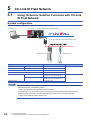
Using iQ Sensor Solution Functions with CC-Link IE Field Network . . . . . . . . . . . . . . . . . . . . . . . . . . . . . . 92
System configuration . . . . . . . . . . . . . . . . . . . . . . . . . . . . . . . . . . . . . . . . . . . . . . . . . . . . . . . . . . . . . . . . . . . . . . 92
Operation procedure . . . . . . . . . . . . . . . . . . . . . . . . . . . . . . . . . . . . . . . . . . . . . . . . . . . . . . . . . . . . . . . . . . . . . . 93
5.2
Easy Startup. . . . . . . . . . . . . . . . . . . . . . . . . . . . . . . . . . . . . . . . . . . . . . . . . . . . . . . . . . . . . . . . . . . . . . . . . . . . 95
Detecting system configuration . . . . . . . . . . . . . . . . . . . . . . . . . . . . . . . . . . . . . . . . . . . . . . . . . . . . . . . . . . . . . . 95
Detecting the system configuration of the MELSEC iQ-R series CC-Link IE Field Network . . . . . . . . . . . . . . 100
5.3
Easy Tuning . . . . . . . . . . . . . . . . . . . . . . . . . . . . . . . . . . . . . . . . . . . . . . . . . . . . . . . . . . . . . . . . . . . . . . . . . . . 104
5.4
Sensor/Device Monitor . . . . . . . . . . . . . . . . . . . . . . . . . . . . . . . . . . . . . . . . . . . . . . . . . . . . . . . . . . . . . . . . . . 106
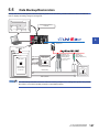
5.5
Data Backup/Restoration . . . . . . . . . . . . . . . . . . . . . . . . . . . . . . . . . . . . . . . . . . . . . . . . . . . . . . . . . . . . . . . . 107
Data backup with programs. . . . . . . . . . . . . . . . . . . . . . . . . . . . . . . . . . . . . . . . . . . . . . . . . . . . . . . . . . . . . . . . 112
Data restoration with programs . . . . . . . . . . . . . . . . . . . . . . . . . . . . . . . . . . . . . . . . . . . . . . . . . . . . . . . . . . . . . 123
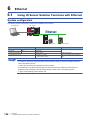
CHAPTER 6
6.1
Ethernet
134
CONTENTS
Verifying system configuration. . . . . . . . . . . . . . . . . . . . . . . . . . . . . . . . . . . . . . . . . . . . . . . . . . . . . . . . . . . . . . 103
Using iQ Sensor Solution Functions with Ethernet . . . . . . . . . . . . . . . . . . . . . . . . . . . . . . . . . . . . . . . . . . . 134
System configuration . . . . . . . . . . . . . . . . . . . . . . . . . . . . . . . . . . . . . . . . . . . . . . . . . . . . . . . . . . . . . . . . . . . . . 134
Operation procedure . . . . . . . . . . . . . . . . . . . . . . . . . . . . . . . . . . . . . . . . . . . . . . . . . . . . . . . . . . . . . . . . . . . . . 135
6.2
Easy Startup. . . . . . . . . . . . . . . . . . . . . . . . . . . . . . . . . . . . . . . . . . . . . . . . . . . . . . . . . . . . . . . . . . . . . . . . . . . 136
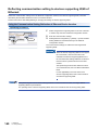
Detecting system configuration . . . . . . . . . . . . . . . . . . . . . . . . . . . . . . . . . . . . . . . . . . . . . . . . . . . . . . . . . . . . . 136
Detecting the system configuration of the MELSEC iQ-R Ethernet. . . . . . . . . . . . . . . . . . . . . . . . . . . . . . . . . . 138
Reflecting communication setting to devices supporting iQSS of Ethernet. . . . . . . . . . . . . . . . . . . . . . . . . . . . 140
6.3
Easy Tuning . . . . . . . . . . . . . . . . . . . . . . . . . . . . . . . . . . . . . . . . . . . . . . . . . . . . . . . . . . . . . . . . . . . . . . . . . . . 142
6.4
Sensor/Device Monitor . . . . . . . . . . . . . . . . . . . . . . . . . . . . . . . . . . . . . . . . . . . . . . . . . . . . . . . . . . . . . . . . . . 144
6.5
Data Backup/Restoration . . . . . . . . . . . . . . . . . . . . . . . . . . . . . . . . . . . . . . . . . . . . . . . . . . . . . . . . . . . . . . . . 145
Data backup with Engineering tool . . . . . . . . . . . . . . . . . . . . . . . . . . . . . . . . . . . . . . . . . . . . . . . . . . . . . . . . . . 149
Data backup with programs. . . . . . . . . . . . . . . . . . . . . . . . . . . . . . . . . . . . . . . . . . . . . . . . . . . . . . . . . . . . . . . . 150
Data restoration with Engineering tool. . . . . . . . . . . . . . . . . . . . . . . . . . . . . . . . . . . . . . . . . . . . . . . . . . . . . . . . 157
Data restoration with program . . . . . . . . . . . . . . . . . . . . . . . . . . . . . . . . . . . . . . . . . . . . . . . . . . . . . . . . . . . . . . 158
CHAPTER 7
7.1
USEFUL FUNCTIONS
165
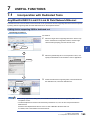
Incorporation with Dedicated Tools. . . . . . . . . . . . . . . . . . . . . . . . . . . . . . . . . . . . . . . . . . . . . . . . . . . . . . . . 165
AnyWireASLINK/CC-Link/CC-Link IE Field Network/Ethernet . . . . . . . . . . . . . . . . . . . . . . . . . . . . . . . . . . . . . 165
7.2
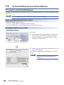
Command Execution to Slave Stations . . . . . . . . . . . . . . . . . . . . . . . . . . . . . . . . . . . . . . . . . . . . . . . . . . . . . 166
CC-Link/CC-Link IE Field Network . . . . . . . . . . . . . . . . . . . . . . . . . . . . . . . . . . . . . . . . . . . . . . . . . . . . . . . . . . 166
APPENDIX
167
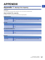
Appendix 1 Backup File Capacity. . . . . . . . . . . . . . . . . . . . . . . . . . . . . . . . . . . . . . . . . . . . . . . . . . . . . . . . . . . . . . . 167
Approximate file capacity. . . . . . . . . . . . . . . . . . . . . . . . . . . . . . . . . . . . . . . . . . . . . . . . . . . . . . . . . . . . . . . . . . 167
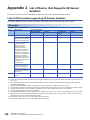
Appendix 2 List of Device that Supports iQ Sensor Solution . . . . . . . . . . . . . . . . . . . . . . . . . . . . . . . . . . . . . . . . 168
List of CPU module supporting iQ Sensor Solution. . . . . . . . . . . . . . . . . . . . . . . . . . . . . . . . . . . . . . . . . . . . . . 168
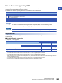
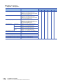
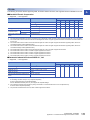
List of devices supporting iQSS. . . . . . . . . . . . . . . . . . . . . . . . . . . . . . . . . . . . . . . . . . . . . . . . . . . . . . . . . . . . . 169
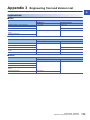
Appendix 3 Engineering Tool and Version List . . . . . . . . . . . . . . . . . . . . . . . . . . . . . . . . . . . . . . . . . . . . . . . . . . . . 173
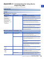
Appendix 4 Considerations for Using Device Supporting iQSS . . . . . . . . . . . . . . . . . . . . . . . . . . . . . . . . . . . . . . 175
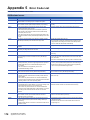
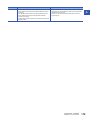
Appendix 5 Error Code List. . . . . . . . . . . . . . . . . . . . . . . . . . . . . . . . . . . . . . . . . . . . . . . . . . . . . . . . . . . . . . . . . . . . 178
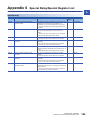
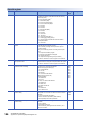
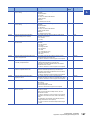
Appendix 6 Special Relay/Special Register List . . . . . . . . . . . . . . . . . . . . . . . . . . . . . . . . . . . . . . . . . . . . . . . . . . . 185
INDEX
190
REVISIONS. . . . . . . . . . . . . . . . . . . . . . . . . . . . . . . . . . . . . . . . . . . . . . . . . . . . . . . . . . . . . . . . . . . . . . . . . . . . .192
7
WARRANTY . . . . . . . . . . . . . . . . . . . . . . . . . . . . . . . . . . . . . . . . . . . . . . . . . . . . . . . . . . . . . . . . . . . . . . . . . . . .193
TRADEMARKS . . . . . . . . . . . . . . . . . . . . . . . . . . . . . . . . . . . . . . . . . . . . . . . . . . . . . . . . . . . . . . . . . . . . . . . . . .194
8
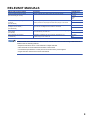
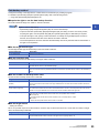
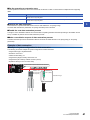
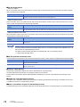
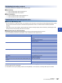
RELEVANT MANUALS
Manual name [manual number]
Description
Available form
iQ Sensor Solution Reference Manual
[SH-081133ENG] (this manual)
Operation methods of the online functions for iQ Sensor Solution
GX Works2 Version 1 Operating Manual
(Common)
[SH-080779ENG]
System configuration, parameter settings, and operation methods of the online
functions (common to Simple project and Structured project) of GX Works2
Print book
GX Works2 Version 1 Operating Manual
(Intelligent Function Module)
[SH-080921ENG]
Operation methods of parameter settings, monitoring, predefined protocol
support function of intelligent function module in GX Works2
Print book
MELSEC-Q CC-Link System Master/Local Module
User's Manual
[SH-080394E]
System configuration, performance specifications, functions, handling, wiring,
and troubleshooting of QJ61BT11N
Print book
FX3U-128ASL-M User's Manual
[JY997D52101]
Specifications, installation and wiring, functions, programming, and
troubleshooting of FX3U-128ASL-M
Print book
Print book
e-Manual
EPUB
PDF
PDF
PDF
PDF
PDF
e-Manual refers to the Mitsubishi FA electronic book manuals that can be browsed using a dedicated tool.
e-Manual has the following features:
• Required information can be cross-searched in multiple manuals.
• Other manuals can be accessed from the links in the manual.
• The hardware specifications of each part can be found from the product figures.
• Pages that users often browse can be bookmarked.
9
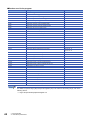
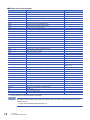
TERMS
Unless otherwise specified, this manual uses the following terms.
Term
10
Description
Actual system configuration
An abbreviation for actual system configuration connected to a master module and Built-in Ethernet port LCPU
Address
A parameter assigned to a slave module to identify each node on the network
AnyWireASLINK
A wire-saving network which provides an appropriate connection between the sensors at the terminal end of a control
system and a programmable controller.
Detecting a sensor disconnection or setting the I/O operation from the upper system can be realized without using the I/
O area.
AnyWireASLINK configuration
An abbreviation for a system configuration connected with AnyWireASLINK
AnyWireASLINK master module
A generic term for LJ51AW12AL, QJ51AW12AL, and FX3U-128ASL-M
ASLINKAMP
A generic term for sensor amplifiers that have an AnyWireASLINK interface
ASLINKER
A generic term for I/O devices that have an AnyWireASLINK interface
Bridge module
An abbreviation for NZ2AW1C2AL CC-Link-AnyWireASLINK bridge module and NZ2AW1GFAL CC-Link IE Field
Network-AnyWireASLINK bridge module
Built-in Ethernet port LCPU
A generic term for L02CPU, L02CPU-P, L06CPU, L06CPU-P, L26CPU, L26CPU-P, L26CPU-BT, and L26CPU-PBT
Built-in Ethernet port CPU
A generic term for L02CPU, L02CPU-P, L06CPU, L06CPU-P, L26CPU, L26CPU-P, L26CPU-BT, L26CPU-PBT,
Q03UDVCPU, Q04UDVCPU, Q06UDVCPU, Q13UDVCPU, and Q26UDVCPU
CC IE Field configuration
An abbreviation for a system configuration connected with CC-Link IE Field Network
CC-Link
This stands for Control and Communication Link.
A field network system where data processing for control and information can be simultaneously performed at high
speed.
CC-Link configuration
An abbreviation for a system configuration connected with CC-Link
CC-Link IE Field Network
A high-speed and large capacity open field network using Ethernet (1000BASE-T)
CC-Link IE Field Network master/
local module
A generic term for LJ71GF11-T2 CC-Link IE Field Network master/local module
CC-Link master/local module
A generic term for LJ61BT11 CC-Link system master/local module, QJ61BT11N CC-Link system master/local module,
L26CPU-BT, and L26CPU-PBT built-in CC-Link system master/local module
CC-Link Ver.2-compatible slave
station
A slave station which supports the remote net Ver.2 mode
Communication setting
A generic term for the settings (such as IP address) to communicate using Ethernet
Connection method
A generic term for the sensor network and each network that can be connected using iQ Sensor Solution
CPU module
A generic term for LCPU, QCPU, RCPU, FXCPU
Device supporting iQSS
A generic term for a device which supports iQ Sensor Solution
Engineering tool
A tool for setting, programming, debugging, and maintaining programmable controllers.
A generic term for GX Works2, GX Works3, and MELSOFT Navigator
Ethernet configuration
An abbreviation for a system configuration connected with Ethernet
FXCPU
A generic term for MELSEC-F series CPU module
GX Works2
A generic product name for model names, SWnDNC-GXW2 ('n' indicates its version.)
GX Works2 Version 1.15R or later supports MELSOFT Navigator.
GX Works3
A generic product name for model names, SWnDND-GXW3 ('n' indicates its version.)
ID
Distinguished output(s) and input(s) based on the address
Output module ID: Address
Input/combined module ID: Address + 200H
iQ Works
An abbreviation for MELSOFT iQ Works
LCPU
A generic term for MELSEC-L series CPU module
MELSEC iQ-R series CC-Link IE
Field Network-equipped master/
local module
A generic term for RJ71GF11-T2 CC-Link IE Field Network master/local module and RJ71EN71 (when the CC-Link IE
Field Network function is used)
MELSOFT Navigator
A product name for the integrated development environment included in SWnDND-IQWK (MELSOFT iQ Works) ('n'
indicates its version.)
Profile
Data in which information of devices supporting iQSS (such as module model names) is stored
QCPU
A generic term for MELSEC-Q series CPU module
RCPU
A generic term for MELSEC iQ-R series CPU module
Remote I/O module
A generic term for Basic Digital Input Module and Basic Digital Output Module of CC-Link IE Field Network.
RnENCPU
A generic term for R04ENCPU, R08ENCPU, R16ENCPU, R32ENCPU, and R120ENCPU
Term
Description
Sensor parameter
A generic term for parameter (such as threshold or sensor operation mode) of devices supporting iQSS
Station sub-ID number
An abbreviation for ID number of a sensor connected to a communication unit for CC-Link
11
1
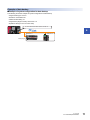
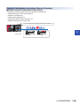
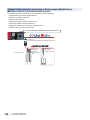
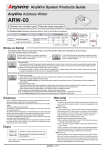
iQ Sensor Solution OVERVIEW
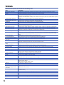
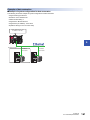
iQ Sensor Solution is a solution that enables a total control of partner products and programmable controllers using
Engineering tool.
By sharing design information including system design and programming in the whole control system, the system design
efficiency and the programming efficiency can be improved, and the total cost of design, startup, operation, and maintenance
can be reduced.
Enables a total control using
Engineering tool
Devices supporting
iQSS
12
1 iQ Sensor Solution OVERVIEW
1.1
Features of iQ Sensor Solution
1
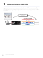
Easy startup
A system configuration diagram can be easily displayed on Engineering tool by detecting devices supporting iQSS from the
actual system configuration.
In addition, the system configuration being displayed can be verified against the actual system configuration, and the
communication settings for Ethernet devices can be configured easily.
Automatic detection function of connected devices
A system configuration diagram can be automatically created on Engineering tool by detecting devices supporting iQSS from
the actual system configuration.
Consequently, man-hours for creating a system configuration diagram at the system startup can be reduced.
Display a system configuration diagram detected automatically on
Engineering tool.
Devices supporting iQSS
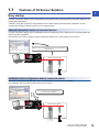
Verification of the configuration with the connected module
The system configuration being displayed can be checked against the actual system configuration.
The modification man-hours at the system startup can be reduced.
Verify the created system configuration against
the actual system configuration.
Devices supporting iQSS
1 iQ Sensor Solution OVERVIEW
1.1 Features of iQ Sensor Solution
13
Communication setting reflection of Ethernet device
Communication settings such as IP address can be configured on the same setting screen for different type of sensors.
Since the setting can be configured to devices supporting iQSS without starting respective dedicated tools, the setting manhours can be reduced.
Communication settings of devices
supporting iQSS can be configured.
Devices supporting iQSS
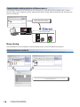
Easy tuning
Sensor parameters can be set efficiently on the same setting screen for sensors of different manufacturers.
Sensor parameter read/write
Sensor parameters can be set by the same operation without starting a dedicated tools by each manufacturer.
Various sensor parameters of devices supporting iQSS can be configured on
the same setting screen.
14
1 iQ Sensor Solution OVERVIEW
1.1 Features of iQ Sensor Solution
Sensor/device monitor
1
The devices supporting iQSS, which are connected to an actual system configuration, can be displayed on a single screen.
Sensor/device monitor
The status of devices supporting iQSS, which are connected to the actual system configuration, can be monitored.
The status and details on devices supporting iQSS can be checked in the Monitor Information window.
The status of device supporting iQSS can be
checked.
Data backup/restoration
Data such as the setting data of devices supporting iQSS can be backed up (saved) to /restored from an SD memory card.
Data backup/restoration
Data such as setting data of devices supporting iQSS, which are connected to the actual system configuration, can be backed
up (saved) to/restored from an SD memory card.
Since the data restoration/utilization is simplified, man-hours for setting change can be reduced.
0
72
104
173
M0
FMOV
K0
M1200
=
H0
SD1436
=
D1000
SD1436
<>
D1000
SD1436
<>
H0
SD1436
K4
RST
M3000
RST
M3500
SET
M1000
SET
M1100
MOV
H1050
D1000
MOV
D1000
SD1435
SET
M1200
SET
M1300
SET
M3550
M1000 SD1288.A
M1100
D5000
Setting data can be backed up/restored at a time.
Setting data
Devices supporting iQSS
1 iQ Sensor Solution OVERVIEW
1.1 Features of iQ Sensor Solution
15
2
iQ Sensor Solution FUNCTION
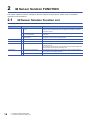
This chapter explains the functions available for iQ Sensor Solution and the iQ Sensor Solution functions available for
respective connection methods.
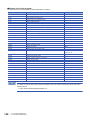
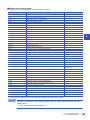
2.1
iQ Sensor Solution Function List
The following table shows the functions available for iQ Sensor Solution.
16
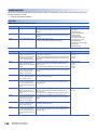
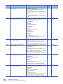
Purpose
iQ Sensor Solution function
Description
Easy startup
Automatic detection of connected
devices
A function to detect devices supporting iQSS, which are connected to a master
module or a Built-in Ethernet port LCPU, and display the information in respective
configuration windows
Verification of the Configuration with
the Connected Module
A function to check a system configuration being displayed against the actual system
configuration
Communication Setting Reflection of
Ethernet Device
A function to reflect the communication settings configured in the Ethernet
Configuration window to devices supporting iQSS
Easy tuning
Sensor parameter read/write
A function to read/write sensor parameters of devices supporting iQSS
Sensor/device monitor
Sensor/Device Monitor
A function to monitor the status of devices supporting iQSS graphically
Data backup/restoration
Data backup/restoration
A function to back up (save) data such as setting data of devices supporting iQSS to
an SD memory card.
And, a function to restore data such as setting data of devices supporting iQSS which
has been backed up (saved) to an SD memory card.
Useful function
Incorporation with dedicated tool
The dedicated tools or manuals can be activated from devices supporting iQSS on
'Device map area' by linking the properties.
Command execution to slave station
Commands can be executed to a slave station connected to a master/local module.
2 iQ Sensor Solution FUNCTION
2.1 iQ Sensor Solution Function List
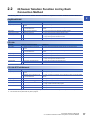
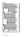
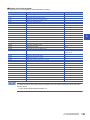
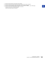
2.2
iQ Sensor Solution Function List by Each
Connection Method
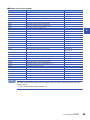
The following tables list the iQ Sensor Solution functions available for respective connection methods and their references.
2
AnyWireASLINK
Purpose
iQ Sensor Solution function
Reference
Easy startup
Automatic detection of connected
devices
Page 21 Using the automatic detection function of connected devices
Verification of the Configuration with
the Connected Module
Page 23 Using the Verification of the Configuration with the Connected Module
function
Easy tuning
Sensor parameter read/write
Page 24 Using the sensor parameter read/write function
Sensor/device monitor
Sensor/Device Monitor
Page 26 Using the Sensor/Device Monitor function
Data backup/restoration
Data backup/restoration
Page 31 Using the data backup function
Page 38 Using the data restoration function
Useful function
Incorporation with dedicated tool
Page 165 Incorporation with Dedicated Tools
Purpose
iQ Sensor Solution function
Reference
Easy startup
Automatic detection of connected
devices
Page 48 Using the automatic detection function of connected devices
Verification of the Configuration with
the Connected Module
Page 55 Using the Verification of the Configuration with the Connected Module
function
Easy tuning
Sensor parameter read/write
Page 57 Using the sensor parameter read/write function
Sensor/device monitor
Sensor/Device Monitor
Page 59 Using the Sensor/Device Monitor function
Data backup/restoration
Data backup/restoration
Page 67 Using the data backup function
Page 79 Using the data restoration function
Useful function
Incorporation with dedicated tool
Page 165 Incorporation with Dedicated Tools
Command execution to slave station
Page 166 Command Execution to Slave Stations
CC-Link
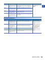
CC-Link IE Field Network
Purpose
iQ Sensor Solution function
Reference
Easy startup
Automatic detection of connected
devices
Page 95 Using the automatic detection function of connected devices
Verification of the Configuration with
the Connected Module*1
Page 103 Using the Verification of the Configuration with the Connected Module
function
Sensor parameter read/write
Page 104 Using the sensor parameter read/write function
Sensor/device monitor
Sensor/Device Monitor
Page 106 Using the Sensor/Device Monitor function
Data backup/restoration
Data backup/restoration*2
Page 112 Data backup with programs
Page 123 Data restoration with programs
Incorporation with dedicated tool
Page 165 Incorporation with Dedicated Tools
Command execution to slave station
Page 166 Command Execution to Slave Stations
Easy tuning
Useful function
*1
*2
This function can be performed to the devices supporting iQSS, which are connected to Bridge module (NZ2AW1GFAL).
This function can be performed only with a program.
2 iQ Sensor Solution FUNCTION
2.2 iQ Sensor Solution Function List by Each Connection Method
17
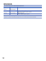
Ethernet
18
Purpose
iQ Sensor Solution function
Reference
Easy startup
Automatic detection of connected
devices
Page 136 Using the automatic detection function of connected devices
Communication Setting Reflection of
Ethernet Device
Page 140 Using the Communication Setting Reflection of Ethernet Device
function
Easy tuning
Sensor parameter read/write
Page 142 Using the sensor parameter read/write function
Sensor/device monitor
Sensor/Device Monitor
Page 144 Using the Sensor/Device Monitor function
Data backup/restoration
Data backup/restoration
Page 149 Using the data backup function
Page 157 Using the data restoration function
Useful function
Incorporation with dedicated tool
Page 165 Incorporation with Dedicated Tools
2 iQ Sensor Solution FUNCTION
2.2 iQ Sensor Solution Function List by Each Connection Method
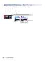
3
AnyWireASLINK
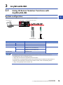
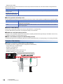
3.1
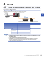
Using iQ Sensor Solution Functions with
AnyWireASLINK
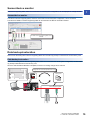
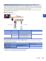
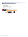
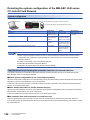
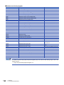
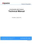
System configuration
3
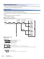
The following system configuration is used for the explanation in this section.
Engineering tool
CPU module
AnyWireASLINK master module
ASLINKAMP (Input)
Type
ASLINKER (Input)
Model name
Manufacturer
Engineering tool
GX Works2
SWnDNC-GXW2 ('n' indicates its version.)
Mitsubishi Electric Corporation
CPU module
LCPU
L26CPU-BT
AnyWireASLINK master module
LJ51AW12AL
ASLINKAMP (Input)
Photoelectric sensor
B289SB-01AP-CAM20 (ASLINKAMP master)
B289SB-01AP-CAS (ASLINKAMP slave)
Fiber sensor
B289SB-01AF-CAS (ASLINKAMP slave)
B289SB-01AF-CAS (ASLINKAMP slave)
ASLINKER (Input)
AnyWire Corporation
B281SB-02U-CC20
• For details on the devices supporting iQSS and the iQ Sensor Solution functions available for
AnyWireASLINK, refer to the following section.
Page 168 List of Device that Supports iQ Sensor Solution
• For information on the Engineering tool that can be used for iQ Sensor Solution and the versions of
Engineering tool that supports each iQ Sensor Solution function, refer to the following section.
Page 173 Engineering Tool and Version List
3 AnyWireASLINK
3.1 Using iQ Sensor Solution Functions with AnyWireASLINK
19
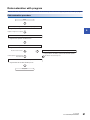
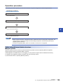
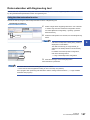
Operation procedure
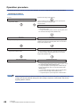
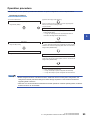
The following shows the operation procedure from detection of system configuration to data backup/restoration.
Operating procedure
Easy Startup
Page 21 Easy Startup
Easy tuning
Page 24 Easy Tuning
Sensor/Device monitor
Page 26 Sensor/Device Monitor
Data Backup/Restoration
Page 27 Data Backup/Restoration
• Before using the functions of iQ Sensor Solution, perform install and wire the actual system configuration,
and configure the PLC parameter settings and other settings required for communication with devices
supporting iQSS (such as the address settings and the amplifier teaching) in advance.
• Make sure that the set address occupied by the slave module does not exceed the number of operating
points set in the master module.
For details on the address setting, refer to the following manual.
MELSEC-Q/L AnyWireASLINK Master Module User's Manual
Before using iQ Sensor Solution functions
■Register profiles
iQ Sensor Solution functions cannot be performed unless the profiles of devices supporting iQSS are registered.
Register profiles of devices supporting iQSS in advance.
Profile registration is available only for a user logging on to the personal computer with the administrator authority.
For details on the registration methods of profiles, refer to the following manual.
GX Works2 Version 1 Operating Manual (Common)
20
3 AnyWireASLINK
3.1 Using iQ Sensor Solution Functions with AnyWireASLINK
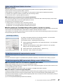
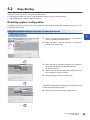
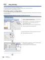
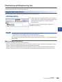
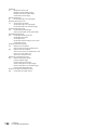
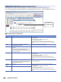
3.2
Easy Startup
Detect a slave module connected to AnyWireASLINK master module in the actual system configuration, and display the
information in the AnyWireASLINK Configuration window.
For the operation methods on the AnyWireASLINK Configuration window, refer to the following manual.
GX Works2 Version 1 Operating Manual (Intelligent Function Module)
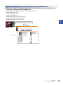
Detecting system configuration
3
The following explains the procedure from detecting devices supporting iQSS automatically to displaying them in the
AnyWireASLINK Configuration window.
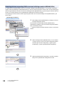
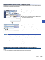
Using the automatic detection function of connected devices
Operating procedure
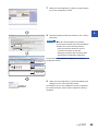
1.
Create a new project with Engineering tool.
( GX Works2 Version 1 Operating Manual (Common))
2.
1. Select
Add the data of AnyWireASLINK master module to "Intelligent
Function Module" on the Project view.
2. Select
3.
Double-click "AnyWireASLINK Configuration" on the Project
view.
Double-click
4.
Select
Select [AnyWireASLINK Configuration] [Online] [Detect
Now] in the AnyWireASLINK Configuration window.
3 AnyWireASLINK
3.2 Easy Startup
21
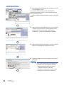
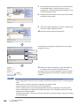
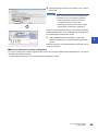
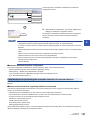
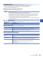
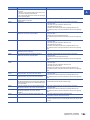
5.
Read the message and select the checkbox. Then, click the
[Yes] button.
Select "Execute Detect Now after Address Autorecognition" in any of the following situations.
1. Check
• Using the automatic detection function of
connected devices for the first time
2. Click
• Resetting or powering OFF the CPU module
• Changing the actual system configuration
The actual system configuration is displayed in the
AnyWireASLINK Configuration window.
List of modules
Device map area
Output window
6.
Select [AnyWireASLINK Configuration] [Close with Saving
the Setting] in the AnyWireASLINK Configuration window.
Select
The settings in the AnyWireASLINK Configuration window are
saved, and the system configuration setting is completed.
• If an error occurred on AnyWireASLINK master module, the system configuration cannot be detected.
Take the appropriate corrective actions, and perform the automatic detection function of connected devices
again.
• When an error occurred, the information is displayed in the Output window.
Double-click the error and correct it at the error jump destination.
• When a module which is not a device supporting iQSS is detected, it is displayed as shown below:
"Module with No Profile Found"
"General Module"
■Detection methods of system configuration
The system configuration of AnyWireASLINK can also be detected by either of the following operations.
• Click the [Detect Now] button in the AnyWireASLINK Configuration window.
• Select [Online] [Detect Now] with MELSOFT Navigator. (FXCPU does not support this function.)
For the operation methods of MELSOFT Navigator, refer to the following manual.
( Let's start iQ Works Version 2)
22
3 AnyWireASLINK
3.2 Easy Startup
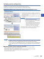
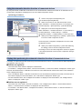
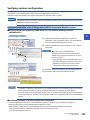
Verifying system configuration
By verifying system configuration, inconsistent parts between the system configuration being displayed and the actual system
configuration can be checked without writing data to the programmable controller CPU.
Verify the system configuration when a system configuration is created manually or edited.
Using the Verification of the Configuration with the Connected Module function
Operating procedure
1.
3
Select [AnyWireASLINK Configuration] [Online]
[Verification of the Configuration with the Connected Module]
1. Select
in the AnyWireASLINK Configuration window.
2.
Read the message and select the checkbox. Then, click the
[Yes] button.
2. Check
Select the "Execute Verification of the
Configuration with the Connected Module after
3. Click
Address Auto-recognition" checkbox in any of the
following situations.
• Using the Verification of the Configuration with
the Connected Module function for the first time
• Resetting or powering OFF the CPU module
• Changing the actual system configuration
The verification results are displayed in the Verification Result of
the Configuration with the Connected Module window.
The display is switched by right-clicking on the Verification Result of the Configuration with the Connected
Module window and selecting "Display All"/"Display Mismatch Only"/"Display other than Match".
■Verification methods of system configuration information
The system configuration information of AnyWireASLINK can also be verified by either of the following operations.
• Click the [Verify] button in the AnyWireASLINK Configuration window.
• Select [Online] [Verification of the Configuration with the Connected Module] with MELSOFT Navigator. (FXCPU does
not support this function.)
For the operation methods of MELSOFT Navigator, refer to the following manual.
( Let's start iQ Works Version 2)
3 AnyWireASLINK
3.2 Easy Startup
23
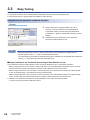
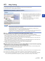
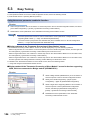
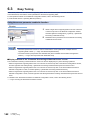
3.3
Easy Tuning
Read/write sensor parameters from/to slave modules.
For the operation methods in the AnyWireASLINK Configuration window, refer to the following manual.
GX Works2 Version 1 Operating Manual (Intelligent Function Module)
Using the sensor parameter read/write function
Window
1.
Select a target device supporting iQSS in the 'List of
modules,' or 'Device map area' in the AnyWireASLINK
2. Select
Configuration window, and then select [AnyWireASLINK
Configuration] [Online] [Parameter Processing of Slave
Module].
1. Select
2.
Read/write the sensor parameters on the "Parameter
Processing of Slave Module" screen.
• Data backup/restoration function is useful to read/write the sensor parameters of multiple devices
supporting iQSS in batch. (Page 27 Data Backup/Restoration)
• The useful function (incorporation with dedicated tool) also is available in the AnyWireASLINK Configuration
window. (Page 165 Incorporation with Dedicated Tools)
■Display methods of the "Parameter Processing of Slave Module" screen
The "Parameter Processing of Slave Module" screen can also be displayed by any of the following operations.
• Select a target module in 'List of modules' or 'Device map area' in the AnyWireASLINK Configuration window, and then
right-click and select [Online] [Parameter Processing of Slave Module] from the shortcut menu.
• Select a target module in the 'List of modules' or 'Device map area' on the "Sensor/Device Monitor for AnyWireASLINK"
screen, and select [Online] [Parameter Processing of Slave Module].
• Select a target module in the 'List of modules' or 'Device map area' on the "Sensor/Device Monitor for AnyWireASLINK"
screen, and then right-click and select [Parameter Processing of Slave Module] from the shortcut menu.
For details on the "Sensor/Device Monitor for AnyWireASLINK" screen, refer to the following section.
Page 26 Using the Sensor/Device Monitor function
24
3 AnyWireASLINK
3.3 Easy Tuning
Reading sensor parameters
Read sensor parameters from the slave module.
Operating procedure
1.
2.
3.
1. Select
Select "Parameter read".
Select the parameter(s) to be read.
Click the [Execute] button.
3
The selected sensor parameters are read and the values are
displayed in the column of "Read Value".
2. Check
3. Click
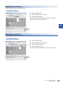
Writing sensor parameters
Write sensor parameters to the slave module.
Operating procedure
1. Select
3. Enter
1.
2.
3.
4.
Select "Parameter write".
Select the parameter(s) to be written.
Enter the values to be written.
Click the [Execute] button.
The values entered in "Write Value" are written to the sensors.
2. Check
4. Click
3 AnyWireASLINK
3.3 Easy Tuning
25
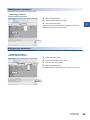
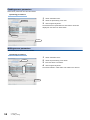
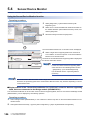
3.4
Sensor/Device Monitor
Monitor the connection status of devices supporting iQSS.
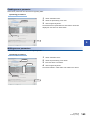
Using the Sensor/Device Monitor function
Operating procedure
1.
Select [Diagnostics] [Sensor/Device Monitor] with
Engineering tool.
1. Select
2.
Select the AnyWireASLINK master module on the "Module
Selection (Sensor/Device Monitor)" screen, and click the [OK]
button.
2. Select
3. Click
3.
Read the message and select the checkbox. Then, click the
[Yes] button.
For details on the selection of the "Execute Detect
2. Click
Now after Address Auto-recognition" checkbox,
1. Check
refer to the restrictions described in the following
section.
Page 21 Using the automatic detection
function of connected devices
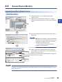
The "Sensor/Device Monitor for AnyWireASLINK" screen is
displayed.
List of modules
4.
Select a device supporting iQSS to be monitored in the 'List
of modules' or 'Device map area' on the "Sensor/Device
Monitor for AnyWireASLINK" screen.
Device map area
The status of the selected devices supporting iQSS is displayed in
the Monitor Information window.
Select
Monitor Information
window
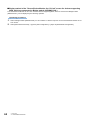
The Sensor/Device Monitor function reads a large volume of information from a CPU module at once.
Therefore, the processing speed of the Sensor/Device Monitor function may decrease depending on the set
communication route.
26
3 AnyWireASLINK
3.4 Sensor/Device Monitor
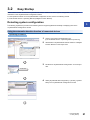
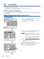
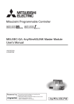
3.5
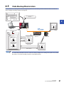
Data Backup/Restoration
Back up data such as setting data of devices supporting iQSS to an SD memory card and restore the data to a module in
order to simplify the setting change for changeover.
0
72
104
173
234
M0
FMOV
K0
M1000 SD1288.A
M1100
M1200
=
H0
SD1436
=
D1000
SD1436
<>
D1000
SD1436
<>
H0
K4
RST
M3000
RST
M3500
SET
M1000
SET
M1100
MOV
H1050
D1000
MOV
D1000
SD1435
SET
M1200
SET
M1300
SET
M3550
MOV
H103
SD1437
MOV
H0FFFF
SD1438
MOV
H3FF
SD1439
MOV
H1
SD1444
SD1436
M1300
D5000
SET
Data backup/restoration
command
3
SM1436
Address 1 to 4
ID513 (201H) to
ID516 (204H)
SD memory card
Address 5
ID517 (205H)
iQSS
ASLINK
20141210_12
Data backup
Address 1
ID513 (201H)
Data restoration
Setting data
0003_IN_ _0513
Address 1
Setting data of
ID513 (201H)
0003_IN_ _0517
Data backup
Address 5
Setting data of
ID517 (205H)
Data restoration
Address 5
ID517 (205H)
Setting data
The data backup/restoration function is useful for switching multiple sensor settings from product A to product
B in batch in such case as limited production of diversified products.
3 AnyWireASLINK
3.5 Data Backup/Restoration
27
Data to be backed up/restored
The data to be backed up/restored are parameters of devices supporting iQSS.
For details on the devices supporting iQSS as the target of the data backup/restoration function, refer to the following section.
Page 168 List of Device that Supports iQ Sensor Solution
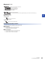
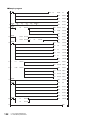
Backup folder/file
Backup data is created under the 'iQSS' folder in the root directory when performing data backup.
If no 'iQSS' folder exists, a new 'iQSS' folder is created at data backup.
Up to 100 backup folders (date_number) can be created in the 'ASLINK' folder.
Do not change the name or configuration of backup folders, or the saved files. If they are changed, data may not be restored
properly.
For the backup file capacity, refer to the following section.
Page 167 Backup File Capacity
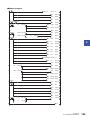
■Backup folder configuration
The following figure shows the backup folder configuration, which is stored in an SD memory card.
1) Backup folder
(Date_Number)
Maximum of 100
Root directory
/
iQSS
ASLINK
20141210_12
2) Backup folder
(Start I/O number_I/O
Type_ID Number)
Backup data
0003_ IN_ _0513
ID_IN__0513.QBR
(Backup file)
SSBRINF.QBI
(System file)
Backup data
0003_ IN_ _0514
ID_IN__0514.QBR
(Backup file)
SSBRINF.QBI
(System file)
■Backup folder name
1) Date_Number
2014 12 10
12
Arbitrary number (2-digit (00 to 99) decimal)
Backup date (2-digit decimal)
Backup month (2-digit decimal)
Backup year (4-digit decimal)
2) Start I/O number_I/O type_ID number
0003
IN_
0513
ID number (4-digit decimal)
OUT or IN_ (OUT: output slave module IN_: input/combined slave module)
AnyWireASLINK master module start I/O number (4-digit hexadecimal) (A value of start I/O number divided by 16)
■Backup file name
ID
IN_
0513 .QBR
ID number (4-digit decimal)
OUT or IN_ (OUT: output slave module IN_: input/combined slave module)
28
3 AnyWireASLINK
3.5 Data Backup/Restoration
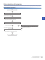
Data backup/restoration methods
The following methods are available to back up/restore data.
■Data backup
• Page 31 Data backup with Engineering tool
• Page 32 Data backup with programs
■Data restoration
• Page 38 Data restoration with Engineering tool
3
• Page 39 Data restoration with programs
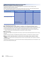
Points to be checked before data backup/restoration
■Check the availability of data backup/restoration
The data backup/restoration function can be performed when AnyWireASLINK master module satisfies the following
conditions.
Perform the automatic address detection function and the parameter batch read function before data backup/restoration.
Condition to be checked
Master module X/Y signal
Signal status
Module READY
Xn0
ON
DP/DN short error
Xn1
OFF
Transmission cable voltage drop error
Xn3
OFF
DP/DN disconnection error
Xn4
OFF
Slave module alarm signal
X(n+1)0
OFF*1
Parameter access completion flag
X(n+1)1
ON
Parameter access error
X(n+1)2
OFF
Automatic address detection flag
X(n+1)4
OFF
*1
Excluding when the error code is 0131H.
Considerations for data backup/restoration
■Use of an SD memory card
• Do not power OFF or reset the module, nor insert/remove an SD memory card during the data backup/restoration process.
Doing so will cause the interruption of the data backup/restoration function, and data cannot be backed up/restored
properly.
• If the memory size or the number of files exceeds the maximum storage capacity of the SD memory card during the data
backup process, normal backup data cannot be created.
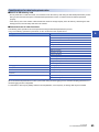
■Concurrent use of other functions
The following online operations cannot be performed during the data backup/restoration process.
If any of the following operations is performed, an error is returned to the request source.
Category
Operation
Drive operation
Format PLC memory
Clear PLC memory (Clear all file registers)
Write title
Program memory batch download
Arrange PLC memory
File operation
Write to PLC
Delete PLC data
Write PLC user data
Delete PLC user data
Password registration
Online change
Online change (ladder mode)
Online change (multiple blocks)
Change TC setting
Online change (files)
3 AnyWireASLINK
3.5 Data Backup/Restoration
29
Category
Operation
Data logging
Data logging registration
FTP operation
For all operations and commands
Trace
Sampling trace registration
Predefined protocol support function (Built-in Ethernet) (Built-in/adapter serial
supported)
Write protocol setting data
Others
Register/cancel display unit menu
CPU module change function with SD memory card
When the data backup/restoration function is performed during the data logging process, the data sampling performance of
the data logging function is degraded.
For that reason, data may be partially missed in the sampled data, or the frequency of missing data may be increased.
■Performing data backup while other functions are running
When any of the following functions is performed during data backup, the data backup process will be completed abnormally,
and the error cause is stored in SD1453 (iQ Sensor Solution backup/restoration error cause in a device).
Function name
File transfer function (FTP server)
File transfer function (FTP client)
CPU module change function with SD memory card
Project data batch save/load function
File delete function on the "Memory card operation menu" screen of display unit
■Operation from display unit during the data backup process
When any of the following operations was performed on a display unit during the data backup process, the operation on the
display unit is completed abnormally, and the error is displayed on the display unit.
Function name
Project data batch save/load function
File delete function on the "Memory card operation menu" screen of display unit
■Communication load
Since the service processing loads increase temporarily once the data backup/restoration function is performed, a timeout
error may occur in other communications.
To prevent the timeout error, review the value of "Service Processing Setting" on the [PLC System] tab of PLC parameter.
■Backup folder name
Do not change the underscore and the subsequent numbers of the backup folder name (date_number).
If they are changed, the data may not be restored properly.
20141210_12
Do not change.
30
3 AnyWireASLINK
3.5 Data Backup/Restoration
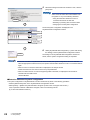
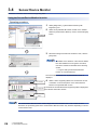
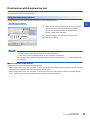
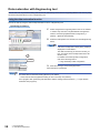
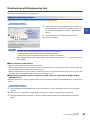
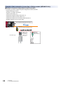
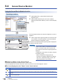
Data backup with Engineering tool
Save data such as parameter setting data of devices supporting iQSS to an SD memory card in units of ID by using the data
backup/restoration function of Engineering tool.
Using the data backup function
Back up the data by using the data backup/restoration function of Engineering tool.
Operating procedure
3
1.
Select a target device supporting iQSS in 'List of modules' or
'Device map area' in the AnyWireASLINK Configuration
2. Select
window, and select [AnyWireASLINK Configuration]
[Online] [Backup Slave Module].
2.
1. Select
Read the message, and click the [Yes] or [OK] button.
Data backup is performed.
The initial values of backup setting (SD1438 and SD1444) are as follows:
• SD1438 (Folder number setting): FFFFH (automatic specification)
• Lower 8 bits of SD1444 (Operation setting for error occurred): 0H (continue)
Use a program when performing data backup with the settings other than above. (Page 32 Data backup
with programs)
■Other methods of data backup
Data backup can be performed by the following methods.
• Select a target module in the 'List of modules' or 'Device map area' in the AnyWireASLINK Configuration window, and then
right-click and select [Backup Slave Module] from the shortcut menu.
• Select a target module in the 'List of modules' or 'Device map area' on the "Sensor/Device Monitor for AnyWireASLINK"
screen, and then right-click and select [Backup Slave Module] from the shortcut menu.
3 AnyWireASLINK
3.5 Data Backup/Restoration
31
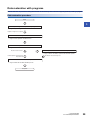
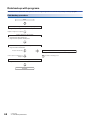
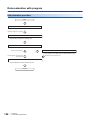
Data backup with programs
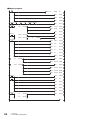
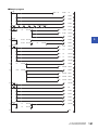
Save data such as parameter setting data of devices supporting iQSS to an SD memory card by creating a program.
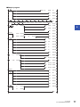
Data backup procedure
Start
Acquire the right to use special relays/registers.
Page 33 Acquire the right to use the data backup function
Completion of right-to-use acquisition
Set the settings for data backup.
Page 33 Set the target module type
Page 34 Set the operation at backup error
Request a data backup.
Page 34 Perform a data backup
Execution of data backup
Request a cancellation of backup process.
Page 34 Make a cancellation request of data backup process
Normal completion of backup process
Backup error
Enable the next backup process.
Page 34 Enable the next data backup process
Complete
32
3 AnyWireASLINK
3.5 Data Backup/Restoration
Cancellation of backup process
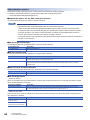
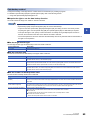
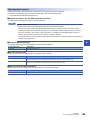
Data backup method
Configure the setting of the target device of which data is to be backed up by creating a program.
For details on special relays (SM) and special registers (SD), refer to the following section.
Page 185 Special Relay/Special Register List
■Acquire the right to use the data backup function
Set a value within the range from 1000H to 1FFFH to SD1435.
3
Rights-to-use for data backup
• Special relays (SM) and special registers (SD) are used for data backup.
• To prevent the same special relay (SM)/special register (SD) from being set in the concurrent process,
acquiring the right to use the special relay (SM) and special register (SD) for data backup is required.
• To acquire the right-to-use, specify a value which does not overlap among multiple request sources to
SD1435, and confirm that the value set to SD1435 is stored to SD1436.
• The normal operations cannot be assured if the data backup function is performed without confirmation of
the right-to-use acquisition.
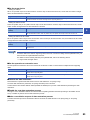
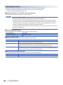
■Set the target module type
Set the target module type for data backup to the lower 8 bits of SD1437.
Target module type
Description
1H: AnyWireASLINK
Set the target module type.
■Set the execution unit
Set the unit of execution for data backup to the upper 8 bits of SD1437.
Execution unit
Description
1H: Module unit
Set this to specify all devices supporting iQSS, which are connected to the AnyWireASLINK interface module with the
specified start I/O number, as the data backup target.
2H: ID unit
Set this to specify the only devices supporting iQSS with the specified ID number out of the devices supporting iQSS,
which are connected to the AnyWireASLINK interface module with the specified start I/O number, as the data backup
target.
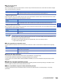
■Set the number for backup folder name
Set the number for backup folder name to SD1438.
Target folder
Description
FFFFH: Automatic specification
(Default)
Uses the smallest number for a new backup folder name among the unused numbers as the backup folder name.
An error occurs when unused number is no longer available due to such cases as the number of folders reached the
upper limit.
FFFEH: Automatic specification
(Folder deletion supported)
Uses the smallest number for a new backup folder name among the unused numbers as the backup folder name.
The oldest folder is deleted and the number of the deleted folder is used for a new backup folder name when unused
number is no longer available due to such cases as the number of folders reached the upper limit.
00 to 99: Target folder specification
Set the number for backup folder name.
When more than one folder with the same number exists, the operation will be as follows:
■For module unit
• The backup folder with the same number is deleted, and a new backup folder is created.
■For ID unit
• Data in the backup folder with the same number is overwritten.
■Set the target device
• Setting the module
When '1H' (module unit) is set for the execution unit in the step of 'Set the execution unit', set the start I/O number of target
device for data backup to SD1439.
Target device (Module)
Description
0 to FFH: Start I/O number
When '1H' (module unit) is set for the execution unit, set the value obtained by dividing the start I/O number of
AnyWireASLINK master module connected to the target devices supporting iQSS by 16.
3 AnyWireASLINK
3.5 Data Backup/Restoration
33
• Setting the ID number
When '2H' (ID unit) is set for the execution unit in the step of 'Set the execution unit', set the ID number of target device for
data backup to SD1440.
Target device (ID number)
Description
0 to 255 (0FFH): Output slave
module ID number
When '2H' (ID unit) is set for the execution unit, set the ID number of target device supporting iQSS.
512 (200H) to 767 (2FFH): Input/
combined slave module ID number*1
*1
Specify the address + 512 (200H) for an input/combined slave module.
■Set the operation at backup error
Set the operation at backup error to the lower 8 bits of SD1444 in order to back up data for multiple devices supporting iQSS.
Operation at error
Description
0H: Continue
Continues the processing even when the data backup fails on some devices during the data backup process for
multiple devices supporting iQSS.
1H: Stop
Terminates the processing when the data backup fails on some devices during the data backup process for multiple
devices supporting iQSS.
■Perform a data backup
Data backup is performed if SM1436 is turned on while SD1446 is '1H' (being ready).
Once the data backup is performed, '2H' (being performed) is set to SD1446.
■Enable the next data backup process
The right-to-use is released if SM1435 is turned ON after completing the data backup (including a cancellation and an error).
It enables to perform the next data backup process.
■Make a cancellation request of data backup process
The data backup process is terminated if SM1442 is turned ON while SD1446 is '1H' (being ready) or '2H' (being performed).
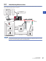
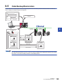
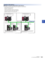
Example of data backup
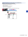
■Example of system configuration for data backup
The following shows the example of system configuration for data backup.
• Target module type: AnyWireASLINK
• Execution unit: Module unit
• Folder number setting: 12
• Target device (target module): Start I/O No. 30
• Operation setting for error occurred: Stop
AnyWireASLINK master module start I/O number 30
Address 1 to 4
ID513 (201H) to
ID516 (204H)
Backup target
34
3 AnyWireASLINK
3.5 Data Backup/Restoration
Address 5
ID517 (205H)
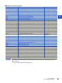
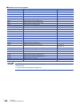
■Devices used in the program
Device
Description
Value
M0
Initialization trigger
M1000
Backup execution trigger
M1100
Backup right-to-use request trigger
M1200
Backup right-to-use confirmation trigger
M1300
Backup setting/start trigger
M2000
Backup execution cancellation trigger
M3000
Backup execution normal completion display
M3500
Backup execution abnormal completion display
M3550
Backup right-to-use acquisition failure
D1000
Right-to-use number storage area
D5000
Backup number of normally completed devices
D5001
Backup number of devices completed with an error
D5002
Backup error cause in a module
D5003
Backup error cause in a device
SM1435
Backup execution enabled
SM1436
Backup request
SM1442
Backup cancellation request
SD1435
Backup use request
1010H
SD1436
Backup right-to-use acquisition status
SD1437
Backup target module/execution unit setting
Lower 8 bits: 1H
Upper 8 bits: 1H
SD1438
Backup folder number setting
12
SD1439
Backup target module setting
3H
SD1444
Backup operation setting for error occurred
1H
SD1446
Backup execution status
SD1448
Backup number of normally completed devices
SD1449
Backup number of devices completed with an error
SD1452
Backup error cause in a module
SD1453
Backup error cause in a device
X30
Module READY
X31
DP/DN short error
X33
Transmission cable voltage drop error
X34
DP/DN disconnection error
X40
Slave module alarm signal
X41
Parameter access completion flag
X42
Parameter access error
X44
Automatic address detection flag
3
For details on special relays (SM) and special registers (SD) to be used and the setting range, refer to the
following section.
Page 185 Special Relay/Special Register List
3 AnyWireASLINK
3.5 Data Backup/Restoration
35
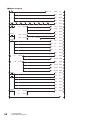
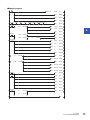
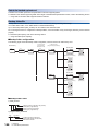
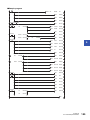
■Sample program
M0
0
8
18
27
41
FMOV K0
X30
M1000
M1100
M1200
=
X31
H0
X33
=
D1000
SD1436
<>
D1000
SD1436
H3
X40
X41
SD1436
M1300
51 =
X34
<>
H0
X42
67
H0FF
M3000
RST
M3500
SET
M1000
SET
M1100
MOV
H1010
D1000
MOV
D1000
SD1435
SET
M1200
SET
M1300
SET
M3550
MOV
H101
SD1437
MOV
K12
SD1438
MOV
H3
SD1439
MOV
H1
SD1444
X44
SD1436
SET
SM1436
SET
M3000
SD1448
D5000
SET
M3500
MOV
SD1449
D5001
MOV
SD1452
D5002
MOV
SD1453
D5003
SD1446
SD1446
M3000
M3500
75
M2000
=
H1
SD1446
=
H2
SD1446
84
36
K4
RST
MOV
57 =
D5000
SET
SM1435
RST
M0
RST
M1000
RST
M1100
RST
M1200
RST
M1300
SET
SM1442
END
3 AnyWireASLINK
3.5 Data Backup/Restoration
[Initialization]
(0)
Initialize the execution result.
Initialize the normal completion display.
Initialize the abnormal completion display.
Set the backup execution trigger.
[Executing data backup]
(8)
Set the backup right-to-use request trigger.
[Requesting backup right-to-use]
(18)
Store the right-to-use number.
Set the backup right-to-use request trigger.
3
Set the backup right-to-use confirmation trigger.
[Confirming backup right-to-use]
(27)
Set the backup setting/start trigger.
Display the backup right-to-use acquisition failure.
[Setting/Starting data backup]
(41)
Set the target module/execution unit.
Set the target folder number.
Set the target module.
Set the backup operation setting for error occurred.
Set the backup request.
[Confirming data backup execution]
(51)
Display the normal completion.
(57)
Display the abnormal completion.
Save the number of normally completed devices.
Save the number of devices completed with an error.
Save the error code (module error).
Save the error code (device error).
[Enabling the next data backup process]
(67)
Enable the data backup execution.
Clear the initialization trigger.
Clear the backup execution trigger.
Clear the backup right-to-use request trigger.
Clear the backup right-to-use confirmation trigger.
Clear the backup setting/start trigger.
[Setting for cancelling the data backup process]
(75)
Set the backup cancellation request.
3 AnyWireASLINK
3.5 Data Backup/Restoration
37
Data restoration with Engineering tool
Restore data such as parameter setting data saved in an SD memory card to devices supporting iQSS in units of ID by using
the data backup/restoration function of Engineering tool.
Using the data restoration function
Restore the data by using the data backup/restoration function of Engineering tool.
Operating procedure
2. Select
1.
Select a target device supporting iQSS in the 'List of modules'
or 'Device map area' in the AnyWireASLINK Configuration
window, and select [AnyWireASLINK Configuration]
[Online] [Restore Slave Module].
1. Select
2.
Select the backup data to be restored, and click the [Execute]
button.
A list of the backup folder names (date_number) is
displayed in "Folder Name".
The data is backed up per 'start I/O number_I/O
type_ID number' in the backup folders in the SD
memory card.
For details on the backup folder configuration,
refer to the following section.
1. Select
Page 28 Backup folder configuration
2. Click
3.
Read the message, and click the [OK] button.
Data restoration is performed.
The initial value of restoration setting (SD1444) is as follows:
• Lower 8 bits of SD1444 (Operation setting for error occurred): 0H (continue)
Use a program when performing data restoration with the settings other than above. (Page 39 Data
restoration with programs)
38
3 AnyWireASLINK
3.5 Data Backup/Restoration
Data restoration with programs
Restore data such as parameter setting data saved in an SD memory card to devices supporting iQSS by creating a program.
Data restoration procedure
Start
3
Acquire the right to use special relays/registers.
Page 40 Acquire the right to use the data restoration function
Completion of right-to-use acquisition
Set the settings for data restoration.
Page 40 Set the target module type
Page 41 Set the operation at restoration error
Request a data restoration
Page 41 Perform the data restoration
Execution of data restoration
Request a cancellation of restoration process.
Page 41 Make a cancellation request of data restoration process
Normal completion of restoration process
Restoration error
Cancellation of restoration process
Enable the next restoration process.
Page 41 Enable the next data restoration process
Complete
3 AnyWireASLINK
3.5 Data Backup/Restoration
39
Data restoration method
Configure the setting of the target device of which data is to be restored by creating a program.
For details on special relays (SM) and special registers (SD), refer to the following section.
Page 185 Special Relay/Special Register List
■Acquire the right to use the data restoration function
Set a value within the range from 1000H to 1FFFH to SD1435.
Rights-to-use for data restoration
• Special relays (SM) and special registers (SD) are used for data restoration.
• To prevent the same special relay (SM)/special register (SD) from being set in the concurrent process,
acquiring the right to use the special relay (SM) and special register (SD) for data restoration is required.
• To acquire the right-to-use, specify a value which does not overlap among multiple request sources to
SD1435, and confirm that the value set to SD1435 is stored to SD1436.
• The normal operation cannot be assured if the data restoration function is performed without confirmation of
the right-to-use acquisition.
■Set the target module type
Set the target module type for data restoration to the lower 8 bits of SD1437.
Target module type
Description
1H: AnyWireASLINK
Set the target module type.
■Set the execution unit
Set the unit of execution for data restoration to the upper 8 bits of SD1437.
Execution unit
Description
1H: Module unit
Set this to specify all devices supporting iQSS, which are connected to the AnyWireASLINK interface module with the
specified start I/O number, as the data restoration target.
2H: ID unit
Set this to specify the only devices supporting iQSS with the specified ID number out of the devices supporting iQSS,
which are connected to the AnyWireASLINK interface module with the specified start I/O number, as the data
restoration target.
■Select a folder for data restoration
Set the number for backup folder name from which data is to be restored to SD1438.
Target folder
Description
00 to 99: Target folder specification
Specify the number among the numbers for backup folder name, 00 to 99.
■Set the target device
• Setting the module
When '1H' (module unit) is set for the execution unit in the step of 'Set the execution unit', set the start I/O number of target
device for data restoration to SD1439.
Target device (Module)
Description
0 to FFH: Start I/O number
When '1H' (module unit) is set for the execution unit, set the value obtained by dividing the start I/O number of
AnyWireASLINK master module connected to the target devices supporting iQSS by 16.
• Setting the ID number
When '2H' (ID unit) is set for the execution unit in the step of 'Set the execution unit', set the ID number of target device for
data restoration to SD1440.
Target device (ID number)
Description
0 to 255 (0FFH): Output slave
module ID number
When '2H' (ID unit) is set for the execution unit, set the ID number of target device supporting iQSS.
512 (200H) to 767 (2FFH): Input/
combined slave module ID number*1
*1
40
Specify the address + 512 (200H) for an input/combined slave module.
3 AnyWireASLINK
3.5 Data Backup/Restoration
■Set the operation at restoration error
Set the operation at restoration error to the lower 8 bits of SD1444 in order to restore data for multiple devices supporting
iQSS.
Operation at error
Description
0H: Continue
Continues the processing even when the data restoration fails on some devices during the data restoration process for
multiple devices supporting iQSS.
1H: Stop
Terminates the processing when the data restoration fails on some devices during the data restoration process for
multiple devices supporting iQSS.
3
■Perform the data restoration
Data restoration is performed if SM1439 is turned on while SD1446 is '1H' (being ready).
Once the data restoration is performed, '2H' (being executed) is set to SD1446.
■Enable the next data restoration process
The right-to-use is released if SM1435 is turned ON after completing the data restoration (including a cancellation and an
error). It enables to perform the next data restoration process.
■Make a cancellation request of data restoration process
The data restoration process is terminated if SM1442 is turned ON while SD1446 is '1H' (being ready) or '2H' (being
performed).
Example of data restoration
■Example of system configuration for data restoration
The following shows the example of system configuration for data restoration.
• Target module type: AnyWireASLINK
• Execution unit: ID unit
• Folder number setting: 12
• Target device (target module): Start I/O No. 30
• Target device (ID number): Address 5, ID517 (205H)
• Operation setting for error occurred: Stop
AnyWireASLINK master module start I/O number 30
Address 1 to 4
ID513 (201H) to
ID516 (204H)
Address 5
ID517 (205H)
Restoration target
3 AnyWireASLINK
3.5 Data Backup/Restoration
41
■Devices used in the program
Device
Description
Value
M0
Initialization trigger
M1000
Restoration execution trigger
M1100
Restoration right-to-use request trigger
M1200
Restoration right-to-use confirmation trigger
M1300
Restoration setting/start trigger
M2000
Restoration execution cancellation trigger
M3000
Restoration execution normal completion display
M3500
Restoration execution abnormal completion display
M3550
Restoration right-to-use acquisition failure
D1000
Right-to-use number storage area
D5000
Restoration number of normally completed devices
D5001
Restoration number of devices completed with an error
D5002
Restoration error cause in a module
D5003
Restoration error cause in a device
SM1435
Restoration execution enabled
SM1439
Restoration request
SM1442
Restoration cancellation request
SD1435
Restoration use request
1020H
SD1436
Restoration right-to-use acquisition status
SD1437
Restoration target module/execution unit setting
Lower 8 bits: 1H
Upper 8 bits: 2H
SD1438
Restoration folder number setting
12
SD1439
Restoration target module setting
3H
SD1440
Restoration target device 1 setting
517
SD1444
Restoration operation setting for error occurred
1H
SD1446
Restoration execution status
SD1448
Restoration number of normally completed devices
SD1449
Restoration number of devices completed with an error
SD1452
Restoration error cause in a module
SD1453
Restoration error cause in a device
X30
Module READY
X31
DP/DN short error
X33
Transmission cable voltage drop error
X34
DP/DN disconnection error
X40
Slave module alarm signal
X41
Parameter access completion flag
X42
Parameter access error
X44
Automatic address detection flag
For details on special relays (SM) and special registers (SD) to be used and the setting range, refer to the
following section.
Page 185 Special Relay/Special Register List
42
3 AnyWireASLINK
3.5 Data Backup/Restoration
■Sample program
M0
0
8
18
27
41
FMOV K0
X30
M1000
M1100
M1200
=
X31
H0
X33
=
D1000
SD1436
<>
D1000
SD1436
H3
X40
X41
SD1436
M1300
53 =
X34
<>
H0
X42
69
H0FF
M3000
RST
M3500
SET
M1000
SET
M1100
MOV
H1020
D1000
MOV
D1000
SD1435
SET
M1200
SET
M1300
SET
M3550
MOV
H201
SD1437
MOV
K12
SD1438
MOV
H3
SD1439
MOV
K517
SD1440
MOV
H1
SD1444
X44
SD1436
SET
SM1439
SET
M3000
SD1448
D5000
SET
M3500
MOV
SD1449
D5001
MOV
SD1452
D5002
MOV
SD1453
D5003
SD1446
SD1446
M3000
M3500
77
86
M2000
=
H1
SD1446
=
H2
SD1446
K4
RST
MOV
59 =
D5000
SET
SM1435
RST
M0
RST
M1000
RST
M1100
RST
M1200
RST
M1300
SET
SM1442
3
END
3 AnyWireASLINK
3.5 Data Backup/Restoration
43
[Initialization]
(0)
Initialize the execution result.
Initialize the normal completion display.
Initialize the abnormal completion display.
Set the restoration execution trigger.
[Executing data restoration]
(8)
Set the restoration right-to-use request trigger.
[Requesting restoration right-to-use]
(18)
Store the right-to-use number.
Set the restoration right-to-use request trigger.
Set the restoration right-to-use confirmation trigger.
[Confirming restoration right-to-use]
(27)
Set the restoration setting/start trigger.
Display the restoration right-to-use acquisition failure.
[Setting/Starting data restoration]
(41)
Set the target module/execution unit.
Set the target folder number.
Set the target module.
Set the target device 1.
Set the restoration operation setting for error occurred.
Set the restoration request.
[Confirming data restoration execution]
(53)
Display the normal completion.
(59)
Display the abnormal completion.
Save the number of normally completed devices.
Save the number of devices completed with an error.
Save the error code (module error).
Save the error code (device error).
[Enabling the next data restoration process]
(69)
Enable the data restoration execution.
Clear the initialization trigger.
Clear the restoration execution trigger.
Clear the restoration right-to-use request trigger.
Clear the restoration right-to-use confirmation trigger.
Clear the restoration setting/start trigger.
[Setting for cancelling the data backup process]
(77)
44
Set the restoration cancellation request.
3 AnyWireASLINK
3.5 Data Backup/Restoration
4
CC-Link
4.1
Using iQ Sensor Solution Functions with CC-Link
System configuration
The following system configuration is used for the explanation in this section.
Engineering tool
CPU module
CC-Link master/local module
4
Analog input module (Voltage/current input)
Type
Model name
Manufacturer
Mitsubishi Electric Corporation
Engineering tool
GX Works2
SWnDNC-GXW2 ('n' indicates its version.)
CPU module
LCPU
L26CPU-BT
CC-Link master/local module
CC-Link Sensor supporting iQSS
LJ61BT11
Analog input module (Voltage/current input)
AJ65SBT2B-64AD
CC-Link sensor supporting
iQSS
Communication unit for
CC-Link
SC-GU3-01
Head-separated dual
display digital pressure
sensor
DPS-401
Digital fiber sensor
FX-501
Digital laser sensor
LS-403
Panasonic Industrial Devices SUNX Co.,
Ltd.
• For details on the devices supporting iQSS and the iQ Sensor Solution functions available for CC-Link, refer
to the following section.
Page 168 List of Device that Supports iQ Sensor Solution
• For information on the Engineering tool that can be used for iQ Sensor Solution and the versions of
Engineering tool that supports each iQ Sensor Solution function, refer to the following section.
Page 173 Engineering Tool and Version List
4 CC-Link
4.1 Using iQ Sensor Solution Functions with CC-Link
45
Operation procedure
The following shows the operation procedure from detection of system configuration to data backup/restoration.
Operating procedure
[Operation after Bridge module detection]
<CC-Link>
Easy startup
iQ Sensor Solution functions available to devices supporting iQSS
which are connected to the Bridge module
<AnyWireASLINK>
Page 48 Easy Startup
Easy startup
• Page 51 Detecting devices supporting iQSS connected to Bridge
module (NZ2AW1C2AL)
• Page 56 Verification methods of devices supporting iQSS, which
are connected to the Bridge module (NZ2AW1C2AL)
Easy tuning
Page 57 Easy Tuning
Sensor/Device monitor
Page 59 Sensor/Device Monitor
Data Backup/Restoration
Page 61 Data Backup/Restoration
Easy tuning
Page 57 Display method of the "Parameter Processing of Slave
Module" screen for devices supporting iQSS, which are connected to
Bridge module (NZ2AW1C2AL)
Sensor/Device monitor
Page 60 Display method of the "Sensor/Device Monitor for CCLink" screen for devices supporting iQSS, which are connected to
Bridge module (NZ2AW1C2AL)
Data Backup/Restoration
Page 61 Data Backup/Restoration
• Page 67 Data backup method for devices supporting iQSS, which
are connected to Bridge module (NZ2AW1C2AL)
• Page 75 Example of system configuration for data backup (for
devices supporting iQSS, which are connected to Bridge module
(NZ2AW1C2AL))
• Page 80 Data restoration method for devices supporting iQSS,
which are connected to Bridge module (NZ2AW1C2AL)
• Page 88 Example of system configuration for data restoration
Before using the functions of iQ Sensor Solution, install and wire the actual system configuration, and
configure the network parameter settings and other settings required for communication with devices
supporting iQSS in advance.
46
4 CC-Link
4.1 Using iQ Sensor Solution Functions with CC-Link
Before using iQ Sensor Solution functions
■Register profiles
iQ Sensor Solution functions cannot be performed unless the profiles of devices supporting iQSS are registered.
Register profiles of devices supporting iQSS in advance.
Profile registration is available only for a user logging on to the personal computer with the administrator authority.
For details on the registration methods of profiles, refer to the following manual.
GX Works2 Version 1 Operating Manual (Common)
■Set devices to be refreshed in the network parameters
Some iQ Sensor Solution functions cannot be performed if devices to refresh the data of remote input (RX), remote output
(RY), remote register (RWr), and remote register (RWw) are not set.
4
Set the devices to be refreshed in advance.
For setting devices to be refreshed, refer to the following manuals.
• MELSEC-Q CC-Link System Master/Local Module User's Manual
• MELSEC-L CC-Link System Master/Local Module User's Manual
■Confirm whether the "Read Model Name of Slave Station" checkbox is selected
When the "Read Model Name of Slave Station" checkbox is not selected, the model name of the slave station cannot be read.
Check whether the "Read Model Name of Slave Station" checkbox has been selected in advance.
If the checkbox is not selected, write the data to the CPU module in accordance with the operating procedures shown below
before performing iQ Sensor Solution functions.
Operating procedure
For details on the display methods of the "Network Parameter - CC-Link Module
Configuration" screen, refer to the following manual.
GX Works2 Version 1 Operating Manual (Common)
1.
Click the [Operation Setting] button on the "Network Parameter - CC-Link Module
Configuration" screen.
2.
Select the "Read Model Name of Slave Station" checkbox on the "Operation
Setting" screen, and click the [OK] button.
2. Click
1. Check
3.
4.
Click the [End] button, and select [Online] [Write to PLC].
Power OFF ON or reset the CPU module.
For devices connected to communication module
Some or all remote registers of the target device are used by the system while iQ Sensor Solution functions are being
performed.
Therefore, add "Remote register use prohibited status (SW0160 to SW0163)" to the interlock when creating a program.
For devices supporting iQSS connected to Bridge module (NZ2AW1C2AL)
■Set the operation mode for CC-Link Ver.2-compatible slave station
Bridge module (NZ2AW1C2AL) is a CC-Link Ver.2-compatible slave station.
To detect Bridge module (NZ2AW1C2AL) to display it on the system configuration diagrams, set to the mode in which CC-Link
Ver.2-compatible slave station operates.
(Page 51 Combination of the mode in which CC-Link Ver.2-compatible slave station operates)
■Set the address of devices supporting iQSS
Configure the settings required for communication (such as address setting and amplifier teaching) in advance in order to use
the iQ Sensor Solution functions for devices supporting iQSS, which are connected to Bridge module (NZ2AW1C2AL).
Make sure that the set address occupied by devices supporting iQSS does not exceed the number of transmission points set
for the Bridge module (NZ2AW1C2AL).
( CC-Link-AnyWireASLINK Bridge Module User's Manual)
4 CC-Link
4.1 Using iQ Sensor Solution Functions with CC-Link
47
4.2
Easy Startup
Detect a slave station connected to CC-Link master/local module in the actual system configuration, and display the
information in the CC-Link Configuration window.
For the operation methods on the CC-Link Configuration window, refer to the following manual.
GX Works2 Version 1 Operating Manual (Common)
Detecting system configuration
The following explains the procedure from detecting devices supporting iQSS automatically to displaying them in the CC-Link
Configuration window.
Using the automatic detection function of connected devices
Operating procedure
1.
Create a new project with Engineering tool. ( GX Works2
Version 1 Operating Manual (Common))
2.
Select
1. Select
Select "Parameter" "Network Parameter" "CC-Link" on
the Project view.
4. Check
3.
Select and enter the necessary parameters on the "Network
Parameter - CC-Link Module Configuration" screen.
3. Click
Confirm that "Read Model Name of Slave Station"
checkbox is selected on the "Operation Setting"
screen.
2.Enter
Page 47 Confirm whether the "Read Model
Name of Slave Station" checkbox is selected
4.
Select the "Set the station information in the CC-Link
configuration window" checkbox.
5.
Read the message and click the [Yes] button.
The [Station Information] button of "Station Information Setting" is
changed to [CC-Link Configuration Setting] button.
6.
Click
48
4 CC-Link
4.2 Easy Startup
Click the [CC-Link Configuration Setting] button.
7.
Select [CC-Link Configuration] [Online] [Detect Now] in
the CC-Link Configuration window.
Select
8.
4
Read the message and select the checkbox. Then, click the
[Yes] button.
Select the "Set the Module Connected the
Communication Module also as the Read Object"
1. Check
checkbox in any of the following situations.
• Using the automatic detection function of
2. Click
connected devices for the first time
• Resetting or powering OFF the CPU module
• Changing the actual system configuration
The actual system configuration is displayed in the CC-Link
List of stations
Configuration window.
Device map area
Output window
9.
Select [CC-Link Configuration] [Close with Reflecting the
Setting] in the CC-Link Configuration window.
Select
The settings in the CC-Link Configuration window are applied to
the network parameter, and the system configuration setting is
completed.
4 CC-Link
4.2 Easy Startup
49
• Once performing the automatic detection function of connected devices, the settings for "Mode" and
"Transmission Speed", which have been configured in CC-Link master/local module, are also detected.
• If an error occurred on the master station, the system configuration cannot be detected.
Take the appropriate corrective actions, and perform the automatic detection function of connected devices
again.
• When an error occurred, the information is displayed in the Output window.
Double-click the error and correct it at the error jump destination.
• When a module which is not a device supporting iQSS is detected, it is displayed as shown below:
"Module with No Profile Found"
"General Module"
• When "Module with No Profile Found" is displayed for the detected module, it can be changed to a generalpurpose CC-Link module by the following operation:
Select the target module, and select [CC-Link Configuration] [Change Module] [Change to General
CC-Link Module].
• Power OFF ON or reset the CPU module after writing the data to the programmable controller CPU when
the automatic CC-Link startup is used. By performing the automatic detection function of connected devices
again, the model name of the slave stations can be read.
For details on the automatic CC-Link startup, refer to the following manuals.
( MELSEC-Q CC-Link System Master/Local Module User's Manual)
( MELSEC-L CC-Link System Master/Local Module User's Manual)
■Detection methods of system configuration
The system configuration of CC-Link can also be detected by either of the following operations.
• Click the [Detect Now] button in the CC-Link Configuration window.
• Select [Online] [Detect Now] with MELSOFT Navigator.
For the operation methods of MELSOFT Navigator, refer to the following manual.
( Let's start iQ Works Version 2)
50
4 CC-Link
4.2 Easy Startup
Detecting devices supporting iQSS connected to Bridge module (NZ2AW1C2AL)
To display devices supporting iQSS, which are connected to Bridge module (NZ2AW1C2AL), on the system configuration
diagram, detecting the Bridge module (NZ2AW1C2AL) in the CC-Link Configuration window at first, and then detecting the
devices supporting iQSS, which are connected to the Bridge module (NZ2AW1C2AL), by performing the automatic detection
function of connected devices in the AnyWireASLINK Configuration window are required.
The system configuration and the operating procedure to detect devices supporting iQSS, which are connected to Bridge
module (NZ2AW1C2AL), are shown below.
■System configuration
CPU module
CC-Link master/local module
4
CC-Link-AnyWireASLINK bridge module
ASLINKAMP (Input)
Type
CPU module
LCPU
ASLINKER (Input)
Model name
Manufacturer
L26CPU-BT
Mitsubishi Electric Corporation
CC-Link master/local module
LJ61BT11
CC-Link-AnyWireASLINK bridge module
NZ2AW1C2AL
ASLINKAMP (Input)
Photoelectric sensor
B289SB-01AP-CAM20 (ASLINKAMP master)
B289SB-01AP-CAS (ASLINKAMP slave)
Fiber sensor
B289SB-01AF-CAS (ASLINKAMP slave)
B289SB-01AF-CAS (ASLINKAMP slave)
ASLINKER (Input)
AnyWire Corporation
B281SB-02U-CC20
■Combination of the mode in which CC-Link Ver.2-compatible slave station operates
Bridge module (NZ2AW1C2AL) is a CC-Link Ver.2-compatible slave station.
The combinations of the parameter settings for CC-Link master/local module and the CC-Link operation mode for Bridge
module (NZ2AW1C2AL) are as follows.
CC-Link master/local module (L26CPU-BT, L26CPU-PBT, LJ61BT11, QJ61BT11N)
Bridge module (NZ2AW1C2AL)
Parameter setting item
CC-Link operation mode
Mode
Station Information (Station Type)
Remote Net (Ver.2 Mode)
Ver.2 remote device station
Ver.2.00
Remote Net (Additional Mode)
For information on CC-Link version and the mode, refer to the following manuals.
• MELSEC-Q CC-Link System Master/Local Module User's Manual
• MELSEC-L CC-Link System Master/Local Module User's Manual
4 CC-Link
4.2 Easy Startup
51
Operating procedure
1.
1. Select
Detect Bridge module (NZ2AW1C2AL) to display it in the CCLink Configuration window.
2. Check
For the method to detect Bridge module (NZ2AW1C2AL)
automatically to display it in the CC-Link Configuration window,
refer to the following section.
Page 48 Using the automatic detection function of connected
3. Click
devices
2. Select
2.
Select the Bridge module (NZ2AW1C2AL) in 'List of stations'
or 'Device map area' in the CC-Link Configuration window,
and select [CC-Link Configuration] [Open System
Configuration] [Open AnyWireASLINK Configuration].
1. Select
3.
Select [AnyWireASLINK Configuration] [Online] [Detect
Now] in the AnyWireASLINK Configuration window.
Select
4.
Read the message and select the checkbox. Then, click the
[Yes] button.
Select "Execute Detect Now after Address Auto1. Check
recognition" in any of the following situations.
• Using the automatic detection function of
2. Click
connected devices for the first time
• Resetting or powering OFF the CPU module
• Changing the actual system configuration
52
4 CC-Link
4.2 Easy Startup
The devices supporting iQSS, which are connected to the Bridge
module (NZ2AW1C2AL), are displayed in the AnyWireASLINK
Select
Configuration window.
5.
Select [AnyWireASLINK Configuration] [Close with
Enabling the Setting] in the AnyWireASLINK Configuration
window.
Enable the settings of the AnyWireASLINK Configuration window,
and close the window.
■Detection methods of system configuration
4
The system configuration of devices supporting iQSS, which are connected to Bridge module (NZ2AW1C2AL), can also be
detected by the following operation.
• Click the [Detect Now] button in the AnyWireASLINK Configuration window.
4 CC-Link
4.2 Easy Startup
53
Considerations for performing the automatic detection of connected devices
The following explains the considerations when performing the automatic detection function of connected devices with CCLink.
■Station numbers of slave station are not sequential
When the automatic detection function of connected devices is performed in the system configuration in which the station
numbers of slave station are not sequential, a general-purpose remote I/O station is automatically set as the reserved station
for the unspecified station number.
Arrange the stations and change the modules in accordance with the actual module configuration.
■"General Module" is displayed
After performing the automatic detection function of connected devices, stations which do not exist in the reserved stations
and the network parameter is performed are displayed as "General Module".
In that case, turn the power OFF once, and turn it ON in the order from the slave station to the master station. Then, perform
the automatic detection function of connected devices again.
■System configuration is changed
When a system configuration is changed (stations are added or changed), the slave station may not be detected.
In that case, turn the power OFF once, and turn it ON in the order from the slave station to the master station. Then, perform
the automatic detection function of connected devices again.
■Standby master station exists in system configuration
When a standby master station exists in a system configuration, the standby master station is set to the last station number.
Change the station number in accordance with the actual system configuration.
■The operation is switched from standby master operation to master operation
When the standby master operation is switched to the master operation, a station of which operation is switched to the master
operation may not be detected.
In that case, turn the power OFF once, and turn it ON in the order from the standby master station to the master station. Then,
perform the automatic detection function of connected devices again.
■Automatic refresh parameters have not been set
The following iQ Sensor Solution functions cannot be performed if the automatic refresh parameters (remote input (RX),
remote output (RY), remote register (RWr), and remote register (RWw)) are not set.
• A function to detect devices supporting iQSS, which are connected to Bridge module, automatically
• Sensor parameter read/write function
Write the automatic refresh parameters to the CPU module before performing the iQ Sensor Solution functions.
For details on the automatic refresh parameters, refer to the following manuals.
• MELSEC-Q CC-Link System Master/Local Module User's Manual
• MELSEC-L CC-Link System Master/Local Module User's Manual
■The "Read Model Name of Slave Station" checkbox is not selected
The following iQ Sensor Solution functions cannot be performed because the model name of slave station cannot be read
unless the "Read Model Name of Slave Station" checkbox on the "Operation Setting" screen is selected.
• The automatic detection function of connected devices, and the Verification of the Configuration with the Connected
Module function
• The Sensor/Device Monitor function
"General CC-Link module" is displayed on the "Sensor/Device Monitor for CC-Link" screen.
• Data backup/restoration function
Select the "Read Model Name of Slave Station" checkbox, and write the data to the CPU module before performing the iQ
Sensor Solution functions.
For the method to select the "Read Model Name of Slave Station" checkbox, refer to the following section.
Page 47 Confirm whether the "Read Model Name of Slave Station" checkbox is selected
54
4 CC-Link
4.2 Easy Startup
Verifying system configuration
By verifying system configuration, inconsistent parts between the system configuration being displayed and the actual system
configuration can be checked without writing data to the programmable controller CPU.
Verify the system configuration when a system configuration is created manually or edited.
Using the Verification of the Configuration with the Connected Module function
Operating procedure
1.
Select [CC-Link Configuration] [Online] [Verification of
the Configuration with the Connected Module] in the CC-Link
4
Configuration window.
1. Select
2.
Read the message and select the checkbox. Then, click the
[Yes] button.
Select "Set the Module Connected the
2. Check
Communication Module also as the Read Object"
in any of the following situations.
3. Click
• Using the Verification of the Configuration with
the Connected Module function for the first time
• Resetting or powering OFF the CPU module
• Changing the actual system configuration
The verification results are displayed in the Verification Result of
the Configuration with the Connected Module window.
• The display is switched by right-clicking on the Verification Result of the Configuration with the Connected
Module window and selecting "Display All"/"Display Mismatch Only"/"Display other than Match".
• The cursor jumps to the corresponding location in the CC-Link Configuration window by double-clicking the
row with "Mismatch" indicated on the Verification Result of the Configuration with the Connected Module
window.
■Verification methods of system configuration information
The system configuration information of CC-Link can also be verified by either of the following operations.
• Click the [Verify] button in the CC-Link Configuration window.
• Select [Online] [Verification of the Configuration with the Connected Module] with MELSOFT Navigator.
For the operation methods of MELSOFT Navigator, refer to the following manual.
( Let's start iQ Works Version 2)
4 CC-Link
4.2 Easy Startup
55
■Verification methods of devices supporting iQSS, which are connected to the Bridge module
(NZ2AW1C2AL)
The system configuration of devices supporting iQSS, which are connected to Bridge module (NZ2AW1C2AL), can also be
verified by the following operation.
Operating procedure
1.
2.
3.
Select the Bridge module (NZ2AW1C2AL) in 'List of stations' or 'Device map area' in the CC-Link Configuration window.
Select [CC-Link Configuration] [Open System Configuration] [Open AnyWireASLINK Configuration].
Select [AnyWireASLINK Configuration] [Online] [Verification of the Configuration with the Connected Module] in the
AnyWireASLINK Configuration window.
56
4 CC-Link
4.2 Easy Startup
4.3
Easy Tuning
Read/write sensor parameters from/to slave stations.
For the operation methods in the CC-Link Configuration window, refer to the following manual.
GX Works2 Version 1 Operating Manual (Common)
Using the sensor parameter read/write function
Window
1.
Select a target device supporting iQSS in 'List of stations' or
4
'Device map area' in the CC-Link Configuration window, and
select [CC-Link Configuration] [Online] [Parameter
Processing of Slave Station].
2. Select
2.
Read/write the sensor parameters on the "Parameter
Processing of Slave Station" screen.
1. Select
• When using CC-Link master/local module (QJ61BT11N), the sensor parameters of inverters (FR-A720
series and FR-A740 series) can be read/written.
• Data backup/restoration function is useful to read/write the sensor parameters of multiple devices
supporting iQSS in batch. (Page 61 Data Backup/Restoration)
• The useful functions (incorporation with dedicated tool, and command execution to slave station) also are
available in the CC-Link Configuration window. (Page 165 USEFUL FUNCTIONS)
■Display methods of the "Parameter Processing of Slave Station" screen
The "Parameter Processing of Slave Station" screen can also be displayed by any of the following operations.
• Select a target module in 'List of stations' or 'Device map area' in the CC-Link Configuration window, and then right-click
and select [Online] [Parameter Processing of Slave Station] from the shortcut menu.
• Select a target module in 'List of stations' or 'Device map area' on the "Sensor/Device Monitor for CC-Link" screen, and
select [Online] [Parameter Processing of Slave Station].
• Select a target module in 'List of stations' or 'Device map area' on the "Sensor/Device Monitor for CC-Link" screen, and
then right-click and select [Parameter Processing of Slave Station] from the shortcut menu.
For details on the "Sensor/Device Monitor for CC-Link" screen, refer to the following section.
Page 59 Using the Sensor/Device Monitor function
■Display method of the "Parameter Processing of Slave Module" screen for devices supporting
iQSS, which are connected to Bridge module (NZ2AW1C2AL)
The "Parameter Processing of Slave Module" screen for devices supporting iQSS, which are connected to Bridge module
(NZ2AW1C2AL), can be displayed by the following operation.
Operating procedure
1.
2.
3.
Select a Bridge module (NZ2AW1C2AL) in 'List of stations' or 'Device map area' in the CC-Link Configuration window.
Select [CC-Link Configuration] [Open System Configuration] [Open AnyWireASLINK Configuration].
Select a target device supporting iQSS in 'List of modules' or 'Device map area' in the AnyWireASLINK Configuration
window, and select [AnyWireASLINK Configuration] [Online] [Parameter Processing of Slave Module].
4 CC-Link
4.3 Easy Tuning
57
Reading sensor parameters
Read sensor parameters from the slave station.
Operating procedure
1.
2.
3.
1. Select
Select "Parameter read".
Select the parameter(s) to be read.
Click the [Execute] button.
The selected sensor parameters are read and the values are
displayed in the column of "Read Value".
2. Check
3. Click
Writing sensor parameters
Write sensor parameters to the slave station.
Operating procedure
1.
2.
3.
4.
1. Select
3. Enter
Select "Parameter write".
Select the parameter(s) to be written.
Enter the values to be written.
Click the [Execute] button.
The values entered in "Write Value" are written to the sensors.
2. Check
4. Click
58
4 CC-Link
4.3 Easy Tuning
4.4
Sensor/Device Monitor
Monitor the connection status of devices supporting iQSS.
Using the Sensor/Device Monitor function
Operating procedure
1.
Select [Diagnostics] [Sensor/Device Monitor] with
Engineering tool.
1. Select
2.
Select the CC-Link master/local module on the "Module
4
Selection (Sensor/Device Monitor)" screen, and click the [OK]
button.
2. Select
3. Click
3.
Read the message and select the checkbox. Then, click the
[Yes] button.
For details on the selection of the "Set the Module
Connected the Communication Module also as the
1. Check
Read Object" checkbox, refer to the restrictions
described in the following section.
2. Click
Page 48 Using the automatic detection
function of connected devices
The "Sensor/Device Monitor for CC-Link" screen is displayed.
4.
Select a target device supporting iQSS to be monitored in
'List of stations' or 'Device map area' on the "Sensor/Device
List of stations
Select
Monitor for CC-Link" screen.
The status of the selected devices supporting iQSS is displayed in
Device map area
the Monitor Information window.
Monitor Information
window
The Sensor/Device Monitor function reads a large volume of information from a CPU module at once.
Therefore, the processing speed of the Sensor/Device Monitor function may decrease depending on the set
communication route.
4 CC-Link
4.4 Sensor/Device Monitor
59
■Display method of the "Sensor/Device Monitor for CC-Link" screen for devices supporting
iQSS, which are connected to Bridge module (NZ2AW1C2AL)
The "Sensor/Device Monitor for CC-Link" screen for devices supporting iQSS, which are connected to Bridge module
(NZ2AW1C2AL), can be displayed by the following operation.
Operating procedure
1.
Select a Bridge module (NZ2AW1C2AL) in 'List of stations' or 'Device map area' on the "Sensor/Device Monitor for CCLink" screen.
2.
60
Select [Sensor/Device Monitor] [Open System Configuration] [Open AnyWireASLINK Configuration].
4 CC-Link
4.4 Sensor/Device Monitor
4.5
Data Backup/Restoration
Back up data such as setting data of devices supporting iQSS to an SD memory card and restore the data to a module in
order to simplify the setting change for changeover.
0
69
114
181
M0
FMOV
M1000
M1100
M1200
X10
=
X1F
H0
X11
K0
SW80.0 SW80.1 SW160.0 SW160.1
SD1436
=
D1000
SD1436
<>
D1000
SD1436
<>
H0
D5000
K4
RST
M3000
RST
M3500
SET
M1000
SET
M1100
MOV
H1030
D1000
MOV
D1000
SD1435
SET
M1200
SET
M1300
SET
M3550
SD1436
Data backup/restoration
command
4
Station sub-ID 1
Setting data
SD memory card
iQSS
CC-Link
20141211_15
Data backup
0001_0001
Setting data of
station No. 1
Data restoration
Station No. 1
Station No.2
Station No. 1
Setting data
0001_0002
Station No.2
Data backup
Setting data of
station No.2
Setting data
Data restoration
The data backup/restoration function is useful for switching multiple sensor settings from product A to product
B in batch in such case as limited production of diversified products.
4 CC-Link
4.5 Data Backup/Restoration
61
Data to be backed up/restored
The data to be backed up/restored are parameters of devices supporting iQSS.
For details on the devices supporting iQSS as the target of the data backup/restoration function, refer to the following section.
Page 168 List of Device that Supports iQ Sensor Solution
Backup folder/file
Backup data is created under the 'iQSS' folder in the root directory when performing data backup.
If no 'iQSS' folder exists, a new 'iQSS' folder is created at data backup.
Up to 100 backup folders (date_number) can be created in the 'CC-Link' folder.
Do not change the name or configuration of backup folders, or the saved files. If they are changed, data may not be restored
properly.
For the backup file capacity, refer to the following section.
Page 167 Backup File Capacity
■Backup folder configuration
The following figure shows the backup folder configuration, which is stored in an SD memory card.
1) Backup folder
(Date_Number)
Maximum of 100
Root directory
/
iQSS
CC-Link
20141211_15
2) Backup folder
(I/O number_Station
number)
Backup data
(Station number)
0001_ 0001
3) STATION0001.QBR
(Backup file)
SSBRINF.QSI
(System file)
Backup data
(Station sub-ID number)
0001_ 0002
4) SUBID0001.QBR
(Backup file)
4) SUBID0002.QBR
(Backup file)
4) SUBID0003.QBR
(Backup file)
SSBRINF.QSI
(System file)
Data backup for devices supporting iQSS, which are connected to Bridge module (NZ2AW1C2AL)
• Backup data is stored in the 'CC-Link' backup folder.
• The station sub-ID number is the same ID number as the AnyWireASLINK address ID.
• The backup file (STATION0000.QBR) for Bridge module is not created.
62
4 CC-Link
4.5 Data Backup/Restoration
■Backup folder name
1) Date_Number
2014 12 11
15
Arbitrary number (2-digit (00 to 99) decimal)
Backup date (2-digit decimal)
Backup month (2-digit decimal)
Backup year (4-digit decimal)
2) Start I/O number_Station number
0001
0001
Station number (4-digit decimal)
CC-Link master/local module start I/O number (4-digit hexadecimal) (A value of start I/O number divided by 16)
■Backup file name
4
3) Station number
STATON0001.QBR
Station number (4-digit decimal)
4) Station sub-ID number
SUBID0001.QBR
Station sub-ID number (4-digit decimal)
Data backup/restoration methods
The following methods are available to back up/restore data.
■Data backup
• Page 67 Data backup with Engineering tool
• Page 68 Data backup with programs
■Data restoration
• Page 79 Data restoration with Engineering tool
• Page 81 Data restoration with program
4 CC-Link
4.5 Data Backup/Restoration
63
Points to be checked before data backup/restoration
■Check the availability of data backup/restoration
The data backup/restoration function can be performed when CC-Link master/local module and Bridge module
(NZ2AW1C2AL) satisfy the following conditions.
Perform the automatic address detection function and the parameter batch read function before data backup/restoration.
The 'n' indicates the address assigned to the master station by the station number setting.
Module
Condition to be checked
Remote device RX signal
Signal status
CC-Link master/local module
Module error
Xn0
OFF
Module READY
XnF
ON
Host station data link status
Xn1
ON
Other station data link status*1
SW0080 to SW0083
OFF
SW0160 to SW0163
OFF
Remote register use prohibited status
Bridge module (NZ2AW1C2AL)
(CC-Link operation mode Ver.2.00)
*1
*2
*1
Remote READY
RX(n+D)B
ON
DP/DN short error
RXn1
OFF
Transmission cable voltage drop error
RXn3
OFF
DP/DN disconnection error
RXn4
OFF
Slave module alarm signal
RX(n+1)0
OFF*2
Parameter access completion flag
RX(n+1)1
ON
Parameter access error
RX(n+1)2
OFF
Automatic address detection flag
RX(n+1)4
OFF
Set the target station.
Excluding when the error code is 0131H.
■The "Read Model Name of Slave Station" checkbox on the "Operation Setting" screen
Confirm that "Read Model Name of Slave Station" checkbox is selected on the "Operation Setting" screen before performing
the data backup/restoration function. If it is not selected, the data backup/restoration function cannot be performed.
For the "Read Model Name of Slave Station" checkbox on the "Operation Setting" screen, refer to the following section.
Page 47 Confirm whether the "Read Model Name of Slave Station" checkbox is selected
■Interlock setting
Some or all remote registers of the target device are used by the system while the data backup/restoration function is being
performed.
Therefore, add "Remote register use prohibited status (SW0160 to SW0163)" to the interlock when creating a program.
■Station of which operating status is switched from the standby master station to master
station
The data backup/restoration function cannot be performed to a station in which the standby master operation is switched to
the master operation.
In that case, turn the power OFF once, and turn it ON in the order from the standby master station to the master station. Then,
perform the data backup/restoration again.
64
4 CC-Link
4.5 Data Backup/Restoration
Considerations for data backup/restoration
■Use of an SD memory card
• Do not power OFF or reset the module, nor insert/remove an SD memory card during the data backup/restoration process.
Doing so will cause the interruption of the data backup/restoration function, and data cannot be backed up/restored
properly.
• If the memory size or the number of files exceeds the maximum storage capacity of the SD memory card during the data
backup process, normal backup data cannot be created.
■Concurrent use of other functions
The following online operations cannot be performed during the data backup/restoration process.
If any of the following operations is performed, an error is returned to the request source.
Category
Operation
Drive operation
Format PLC memory
4
Clear PLC memory (Clear all file registers)
Write title
Program memory batch download
Arrange PLC memory
File operation
Write to PLC
Delete PLC data
Write PLC user data
Delete PLC user data
Password registration
Online change
Online change (ladder mode)
Online change (multiple blocks)
Change TC setting
Online change (files)
Data logging
Data logging registration
FTP operation
For all operations and commands
Trace
Sampling trace registration
Predefined protocol support function (Built-in Ethernet) (Built-in/adapter serial
supported)
Write protocol setting data
Others
Register/cancel display unit menu
CPU module change function with SD memory card
When the data backup/restoration function is performed during the data logging process, the data sampling performance of
the data logging function is degraded.
For that reason, data may be partially missed in the sampled data, or the frequency of missing data may be increased.
4 CC-Link
4.5 Data Backup/Restoration
65
■Performing data backup while other functions are running
When any of the following functions is performed during data backup, the data backup process will be completed abnormally,
and the error cause is stored in SD1453 (iQ Sensor Solution backup/restoration error cause in a device).
Function name
File transfer function (FTP server)
File transfer function (FTP client)
CPU module change function with SD memory card
Project data batch save/load function
File delete function on the "Memory card operation menu" screen of display unit
■Operation from display unit during the data backup process
When any of the following operations was performed on a display unit during the data backup process, the operation on the
display unit is completed abnormally, and the error is displayed on the display unit.
Function name
Project data batch save/load function
File delete function on the "Memory card operation menu" screen of display unit
■Communication load
Since the service processing loads increase temporarily once the data backup/restoration function is performed, a timeout
error may occur in other communications.
To prevent the timeout error, review the value of "Service Processing Setting" on the [PLC System] tab of PLC parameter.
■Backup folder name
Do not change the underscore and the subsequent numbers of the backup folder name (date_number).
If they are changed, the data may not be restored properly.
20141210_12
Do not change.
66
4 CC-Link
4.5 Data Backup/Restoration
Data backup with Engineering tool
Save data such as parameter setting data of devices supporting iQSS to an SD memory card in units of station by using the
data backup/restoration function of Engineering tool.
Using the data backup function
Back up the data by using the data backup/restoration function of Engineering tool.
Operating procedure
1.
Select a target device supporting iQSS in 'List of stations' or
'Device map area' in the CC-Link Configuration window, and
4
select [CC-Link Configuration] [Online] [Backup Slave
2. Select
Station].
2.
1. Select
Read the message, and click the [Yes] or [OK] button.
Data backup is performed.
The initial values of backup setting (SD1438 and SD1444) are as follows:
• SD1438 (Folder number setting): FFFFH (automatic specification)
• Lower 8 bits of SD1444 (Operation setting for error occurred): 0H (continue)
Use a program when performing data backup with the settings other than above. (Page 68 Data backup
with programs)
■Other methods of data backup
Data backup can be performed by the following methods.
• Select a target module in the 'List of stations' or 'Device map area' in the CC-Link Configuration window, and then right-click
and select [Backup Slave Station] from the shortcut menu.
• Select a target module in the 'List of stations' or 'Device map area' on the "Sensor/Device Monitor for CC-Link" screen, and
then right-click and select [Backup Slave Station] from the shortcut menu.
■Data backup method for devices supporting iQSS, which are connected to Bridge module
(NZ2AW1C2AL)
Data can be backed up for devices supporting iQSS, which are connected to Bridge module (NZ2AW1C2AL), by the following
method.
Operating procedure
1.
Select the Bridge module (NZ2AW1C2AL) in the 'List of stations' or 'Device map area' in the CC-Link Configuration
window.
2.
3.
Select [CC-Link Configuration] [Open System Configuration] [Open AnyWireASLINK Configuration].
Select [AnyWireASLINK Configuration] [Online] [Backup Slave Module] in the AnyWireASLINK Configuration
window.
4 CC-Link
4.5 Data Backup/Restoration
67
Data backup with programs
Save data such as parameter setting data of devices supporting iQSS to an SD memory card by creating a program.
Data backup procedure
Start
Acquire the right to use special relays/registers.
Page 69 Acquire the right to use the data backup function
Completion of right-to-use acquisition
Set the settings for data backup.
Page 69 Set the target module type
Page 70 Set the operation at backup error
Request a data backup.
Page 70 Perform a data backup
Execution of data backup
Request a cancellation of backup process.
Page 70 Make a cancellation request of data backup process
Normal completion of backup process
Backup error
Enable the next backup process.
Page 70 Enable the next data backup process
Complete
68
4 CC-Link
4.5 Data Backup/Restoration
Cancellation of backup process
Data backup method
Configure the setting of the target device of which data is to be backed up by creating a program.
For details on special relays (SM) and special registers (SD), refer to the following section.
Page 185 Special Relay/Special Register List
■Acquire the right to use the data backup function
Set a value within the range from 1000H to 1FFFH to SD1435.
Rights-to-use for data backup
• Special relays (SM) and special registers (SD) are used for data backup.
• To prevent the same special relay (SM)/special register (SD) from being set in the concurrent process,
4
acquiring the right to use the special relay (SM) and special register (SD) for data backup is required.
• To acquire the right-to-use, specify a value which does not overlap among multiple request sources to
SD1435, and confirm that the value set to SD1435 is stored to SD1436.
• The normal operations cannot be assured if the data backup function is performed without confirmation of
the right-to-use acquisition.
■Set the target module type
Set the target module type for data backup to the lower 8 bits of SD1437.
Target module type
Description
2H: CC-Link
Set the target module type.
■Set the execution unit
Set the unit of execution for data backup to the upper 8 bits of SD1437.
Execution unit
Description
1H: Module unit
Set this to specify all devices supporting iQSS, which are connected to the CC-Link master/local module with the
specified start I/O number, as the data backup target.
2H: Station unit
Set this to specify the devices supporting iQSS with the specified station number or all of the devices supporting iQSS
connected to the specified station number, out of the devices supporting iQSS, which are connected to the CC-Link
master/local module with the specified start I/O number, as the data backup target.
3H: Station sub-ID unit
Set this to specify the devices supporting iQSS with the specified station sub-ID number, which are connected to the
specified station number, out of devices supporting iQSS, connected to the CC-Link master/local module with the
specified start I/O number as the data backup target.
■Set the number for backup folder name
Set the number for backup folder name to SD1438.
Target folder
Description
FFFFH: Automatic specification
(Default)
Uses the smallest number for a new backup folder name among the unused numbers as the backup folder name.
An error occurs when unused number is no longer available due to such cases as the number of folders reached the
upper limit.
FFFEH: Automatic specification
(Folder deletion supported)
Uses the smallest number for a new backup folder name among the unused numbers as the backup folder name.
The oldest folder is deleted and the number of the deleted folder is used for a new backup folder name when unused
number is no longer available due to such cases as the number of folders reached the upper limit.
00 to 99: Target folder specification
Set the number for backup folder name.
When more than one folder with the same number exists, the operation will be as follows:
■For module unit
• The backup folder with the same number is deleted, and a new backup folder is created.
■For station unit or station sub-ID unit
• Data in the backup folder with the same number is overwritten.
4 CC-Link
4.5 Data Backup/Restoration
69
■Set the target device
• Setting the module
When '1H' (module unit) is set for the execution unit in the step of 'Set the execution unit', set the start I/O number of target
device for data backup to SD1439.
Target device (Module)
Description
0 to FFH: Start I/O number
When '1H' (module unit) is set for the execution unit, set the value obtained by dividing the start I/O number of CC-Link
master/local module connected to the target devices supporting iQSS by 16.
• Setting the station number
When '2H' (station unit) or '3H' (station sub-ID unit) is set for the execution unit in the step of 'Set the execution unit', set the
station number of target device for data backup to SD1440.
Target device (Station
number)
Description
1 to 64: Station number
Set the station number of the target device supporting iQSS or the devices supporting iQSS, which are connected to
the specified station number, when '2H' (station unit) or '3H' (station sub-ID unit) is set for the execution unit.
• Setting the station sub-ID number
When '3H' (station sub-ID unit) is set for the execution unit in the step of 'Set the execution unit', set the station sub-ID number
of target device for data backup to SD1441.
Target device (Station sub-ID
number)
Description
0 to 9999: Station sub-ID number
Set the station sub-ID number of the target device supporting iQSS when '3H' (station sub-ID unit) is set for the
execution unit.
To back up data for the devices supporting iQSS, which are connected to Bridge module (NZ2AW1C2AL), set
the ID number of AnyWireASLINK to SD1441.
For details on the ID number (SD1440) of AnyWireASLINK, refer to the following section.
Page 33 Set the target device
■Set the operation at backup error
Set the operation at backup error to the lower 8 bits of SD1444 in order to back up data for multiple devices supporting iQSS.
Operation at error
Description
0H: Continue
Continues the processing even when the data backup fails on some devices during the data backup process for
multiple devices supporting iQSS.
1H: Stop
Terminates the processing when the data backup fails on some devices during the data backup process for multiple
devices supporting iQSS.
■Perform a data backup
Data backup is performed if SM1436 is turned on while SD1446 is '1H' (being ready).
Once the data backup is performed, '2H' (being performed) is set to SD1446.
Confirm that the other station data link status (SW0080 to SW0083) is in process of data link before performing the data
backup.
■Enable the next data backup process
The right-to-use is released if SM1435 is turned ON after completing the data backup (including a cancellation and an error).
It enables to perform the next data backup process.
■Make a cancellation request of data backup process
The data backup process is terminated if SM1442 is turned ON while SD1446 is '1H' (being ready) or '2H' (being performed).
70
4 CC-Link
4.5 Data Backup/Restoration
Example of data backup
■Example of system configuration for data backup
The following shows the example of system configuration for data backup.
• Target module type: CC-Link
• Execution unit: Module unit
• Folder number setting: 15
• Target device (target module): Start I/O No. 10
• Operation setting for error occurred: Stop
CC-Link master/local module start I/O number 10
4
Station No. 1
Station No. 2
Backup target
4 CC-Link
4.5 Data Backup/Restoration
71
■Devices used in the program
Device
Description
Value
M0
Initialization trigger
M1000
Backup execution trigger
M1100
Backup right-to-use request trigger
M1200
Backup right-to-use confirmation trigger
M1300
Backup setting/start trigger
M2000
Backup execution cancellation trigger
M3000
Backup execution normal completion display
M3500
Backup execution abnormal completion display
M3550
Backup right-to-use acquisition failure
D1000
Right-to-use number storage area
D5000
Backup number of normally completed devices
D5001
Backup number of devices completed with an error
D5002
Backup error cause in a module
D5003
Backup error cause in a device
SM1435
Backup execution enabled
SM1436
Backup request
SM1442
Backup cancellation request
SD1435
Backup use request
1030H
SD1436
Backup right-to-use acquisition status
SD1437
Backup target module/execution unit setting
Lower 8 bits: 2H
Upper 8 bits: 1H
SD1438
Backup folder number setting
15
SD1439
Backup target module setting
1H
SD1444
Backup operation setting for error occurred
1H
SD1446
Backup execution status
SD1448
Backup number of normally completed devices
SD1449
Backup number of devices completed with an error
SD1452
Backup error cause in a module
SD1453
Backup error cause in a device
SW80.0
Station No.1 data link status
SW80.1
Station No.2 data link status
SW160.0
Station No.1 remote register use prohibited status
SW160.1
Station No.2 remote register use prohibited status
X10
Module error
X11
Host station data link status
X1F
Module READY
For details on special relays (SM) and special registers (SD) to be used and the setting range, refer to the
following section.
Page 185 Special Relay/Special Register List
72
4 CC-Link
4.5 Data Backup/Restoration
■Sample program
M0
0
8
17
26
40
FMOV K0
X10
M1000
M1100
M1200
=
X11
H0
X1F
=
D1000
SD1436
<>
D1000
SD1436
M1300
50 =
H3
<>
H0
M3000
RST
M3500
SET
M1000
SET
M1100
MOV
H1030
D1000
MOV
D1000
SD1435
SET
M1200
SET
M1300
SET
M3550
MOV
H102
SD1437
MOV
K15
SD1438
MOV
H1
SD1439
MOV
H1
SD1444
SD1436
SET
SM1436
SET
M3000
SD1448
D5000
SET
M3500
MOV
SD1449
D5001
MOV
SD1452
D5002
MOV
SD1453
D5003
SD1446
MOV
56 =
66
H0FF
SD1446
M3000
M3500
74
83
M2000
=
H1
SD1446
=
H2
SD1446
K4
RST
SW80.0 SW80.1 SW160.0 SW160.1
SD1436
D5000
SET
SM1435
RST
M0
RST
M1000
RST
M1100
RST
M1200
RST
M1300
SET
SM1442
4
END
4 CC-Link
4.5 Data Backup/Restoration
73
[Initialization]
(0)
Initialize the execution result.
Initialize the normal completion display.
Initialize the abnormal completion display.
Set the backup execution trigger.
[Executing data backup/Checking data link status]
Confirm that the other station data link status (SW0080 to SW0083) is in process of data link before executing the data backup request.
(8)
Set the backup right-to-use request trigger.
[Requesting backup right-to-use]
(17)
Store the right-to-use number.
Set the backup right-to-use request trigger.
Set the backup right-to-use confirmation trigger.
[Confirming backup right-to-use]
(26)
Set the backup setting/start trigger.
Display the backup right-to-use acquisition failure.
[Setting/Starting data backup]
(40)
Set the target module/execution unit.
Set the target folder number.
Set the target module.
Set the backup operation setting for error occurred.
Set the backup request.
[Confirming data backup execution]
(50)
Display the normal completion.
(56)
Display the abnormal completion.
Save the number of normally completed devices.
Save the number of devices completed with an error.
Save the error code (module error).
Save the error code (device error).
[Enabling the next data backup process]
(66)
Enable the data backup execution.
Clear the initialization trigger.
Clear the backup execution trigger.
Clear the backup right-to-use request trigger.
Clear the backup right-to-use confirmation trigger.
Clear the backup setting/start trigger.
[Setting for cancelling the data backup process]
(74)
74
Set the backup cancellation request.
4 CC-Link
4.5 Data Backup/Restoration
Example of data backup (connecting to Bridge module (NZ2AW1C2AL))
■Example of system configuration for data backup (for devices supporting iQSS, which are
connected to Bridge module (NZ2AW1C2AL))
The following shows the example of system configuration for data backup.
• Target module type: CC-Link
• Execution unit: Station unit
• Folder number setting: 18
• Target device (target module): Start I/O No. 10
• Target device (station number): Station No. 1
• Operation setting for error occurred: Stop
4
CC-Link master/local module start I/O number 10
Station No. 1
CC-Link-AnyWireASLINK bridge module
Backup target
Address 1 to 4
ID513 (201H) to
ID516 (204H)
(Station sub-ID
513 to 516)
Address 5
ID517(205H)
(Station sub-ID 517)
4 CC-Link
4.5 Data Backup/Restoration
75
■Devices used in the program
Device
Description
Value
M0
Initialization trigger
M1000
Backup execution trigger
M1100
Backup right-to-use request trigger
M1200
Backup right-to-use confirmation trigger
M1300
Backup setting/start trigger
M2000
Backup execution cancellation trigger
M3000
Backup execution normal completion display
M3500
Backup execution abnormal completion display
M3550
Backup right-to-use acquisition failure
D1000
Right-to-use number storage area
D2000.1*1
DP/DN short error
D2000.3*1
Transmission cable voltage drop error
D2000.4*1
DP/DN disconnection error
D2001.0*1
Slave module alarm signal
D2001.1*1
Parameter access completion flag
D2001.2*1
Parameter access error
D2001.4*1
Automatic address detection flag
D2013.B*1
Remote READY
D5000
Backup number of normally completed devices
D5001
Backup number of devices completed with an error
D5002
Backup error cause in a module
D5003
Backup error cause in a device
SM1435
Backup execution enabled
SM1436
Backup request
SM1442
Backup cancellation request
SD1435
Backup use request
1090H
SD1436
Backup right-to-use acquisition status
SD1437
Backup target module/execution unit setting
Lower 8 bits: 2H
Upper 8 bits: 2H
SD1438
Backup folder number setting
18
SD1439
Backup target module setting
1H
SD1440
Backup target device 1 setting
1
SD1444
Backup operation setting for error occurred
1H
SD1446
Backup execution status
SD1448
Backup number of normally completed devices
SD1449
Backup number of devices completed with an error
SD1452
Backup error cause in a module
SD1453
Backup error cause in a device
SW80.0
Station No.1 data link status
SW160.0
Station No.1 remote register use prohibited status
X10
Module error
X11
Host station data link status
X1F
Module READY
*1
A device used when the remote input (RX) is set to D2000.
For details on special relays (SM) and special registers (SD) to be used and the setting range, refer to the
following section.
Page 185 Special Relay/Special Register List
76
4 CC-Link
4.5 Data Backup/Restoration
■Sample program
M0
0
8
32
46
X10
M1000
K0
23
FMOV K0
M1100
M1200
X11
X1F
H0
SD1436
=
D1000
SD1436
<>
D1000
SD1436
M1300
58 =
H3
<>
H0
74
H0FF
82
91
M2000
=
H1
SD1446
=
H2
SD1446
M3500
SET
M1000
K0
MOV
H1090
D1000
MOV
D1000
SD1435
SET
M1200
SET
M1300
SET
M3550
MOV
H202
SD1437
MOV
K18
SD1438
MOV
H1
SD1439
MOV
K1
SD1440
MOV
H1
SD1444
SD1436
SET
SM1436
SET
M3000
SD1448
D5000
SET
M3500
MOV
SD1449
D5001
MOV
SD1452
D5002
MOV
SD1453
D5003
SD1446
M3500
RST
M1100
SD1446
M3000
M3000
SET
MOV
64 =
K4
RST
SW80.0 SW160.0 D2013.B D2000.1 D2000.3 D2000.4 D2001.0
D2001.1 D2001.2 D2001.4
=
D5000
SET
SM1435
RST
M0
RST
M1000
RST
M1100
RST
M1200
RST
M1300
SET
SM1442
4
END
4 CC-Link
4.5 Data Backup/Restoration
77
[Initialization]
(0)
Initialize the execution result.
Initialize the normal completion display.
Initialize the abnormal completion display.
Set the backup execution trigger.
[Executing data backup/Checking data link status]
Confirm that the other station data link status (SW0080 to SW0083) is in process of data link before performing the data backup request.
(8)
Set the backup right-to-use request trigger.
[Requesting backup right-to-use]
(23)
Store the right-to-use number.
Set the backup right-to-use request trigger.
Set the backup right-to-use confirmation trigger.
[Confirming backup right-to-use]
(32)
Set the backup setting/start trigger.
Display the backup right-to-use acquisition failure.
[Setting/Starting data backup]
(46)
Set the target module/execution unit.
Set the target folder number.
Set the target module.
Set the target device 1.
Set the backup operation setting for error occurred.
Set the backup request.
[Confirming data backup execution]
(58)
Display the normal completion.
(64)
Display the abnormal completion.
Save the number of normally completed devices.
Save the number of devices completed with an error.
Save the error code (module error).
Save the error code (device error).
[Enabling the next data backup process]
(74)
Enable the data backup execution.
Clear the initialization trigger.
Clear the backup execution trigger.
Clear the backup right-to-use request trigger.
Clear the backup right-to-use confirmation trigger.
Clear the backup setting/start trigger.
[Setting for cancelling the data backup process]
(82)
78
Set the backup cancellation request.
4 CC-Link
4.5 Data Backup/Restoration
Data restoration with Engineering tool
Restore data such as parameter setting data saved in an SD memory card to devices supporting iQSS in units of station by
using the data backup/restoration function of Engineering tool.
Using the data restoration function
Restore the data by using the data backup/restoration function of Engineering tool.
Operating procedure
1.
Select a target device supporting iQSS in the 'List of stations'
or 'Device map area' in the CC-Link Configuration window,
4
and select [CC-Link Configuration] [Online] [Restore
Slave Station].
2. Select
2.
Select the backup data to be restored, and click the [Execute]
button.
1. Select
A list of the backup folder names (date_number) is
displayed in "Folder Name".
The data is backed up per 'start I/O
number_station number' in the backup folders in
the SD memory card.
For details on the backup folder configuration,
refer to the following section.
1. Select
Page 62 Backup folder configuration
2. Click
3.
Read the message, and click the [OK] button.
Data restoration is performed.
The initial value of restoration setting (SD1444) is as follows:
• Lower 8 bits of SD1444 (Operation setting for error occurred): 0H (continue)
Use a program when performing data restoration with the settings other than above. (Page 81 Data
restoration with program)
4 CC-Link
4.5 Data Backup/Restoration
79
■Data restoration method for devices supporting iQSS, which are connected to Bridge module
(NZ2AW1C2AL)
Data can be restored for devices supporting iQSS, which are connected to Bridge module (NZ2AW1C2AL), by the following
method.
Operating procedure
1.
2.
3.
Select the Bridge module (NZ2AW1C2AL) in 'List of stations' or 'Device map area' in the CC-Link Configuration window.
Select [CC-Link Configuration] [Open System Configuration] [Open AnyWireASLINK Configuration].
Select [AnyWireASLINK Configuration] [Online] [Restore Slave Module] in the AnyWireASLINK Configuration
window.
When restoring data for devices supporting iQSS, which are connected to Bridge module (NZ2AW1C2AL), a
list of the backup data name (date_number) stored in the backup folder of CC-Link is displayed in the "Folder
Name" on the "Select Restoring Backup Data (AnyWireASLINK)" screen.
The data is backed up per 'station number/station sub-ID number' in the backup folders in the SD memory
card.
For details on the backup folder configuration, refer to the following section.
Page 62 Backup folder configuration
80
4 CC-Link
4.5 Data Backup/Restoration
Data restoration with program
Restore data such as parameter setting data saved in an SD memory card to devices supporting iQSS by creating a program.
Data restoration procedure
Start
Acquire the right to use special relays/registers.
Page 82 Acquire the right to use the data restoration function
4
Completion of right-to-use acquisition
Set the settings for data restoration.
Page 82 Set the target module type
Page 83 Set the operation at restoration error
Request a data restoration
Page 83 Perform the data restoration
Execution of data restoration
Request a cancellation of restoration process.
Page 83 Make a cancellation request of data restoration process
Normal completion of restoration process
Restoration error
Cancellation of restoration process
Enable the next restoration process.
Page 83 Enable the next data restoration process
Complete
4 CC-Link
4.5 Data Backup/Restoration
81
Data restoration method
Configure the setting of the target device of which data is to be restored by creating a program.
For details on special relays (SM) and special registers (SD), refer to the following section.
Page 185 Special Relay/Special Register List
■Acquire the right to use the data restoration function
Set a value within the range from 1000H to 1FFFH to SD1435.
Rights-to-use for data restoration
• Special relays (SM) and special registers (SD) are used for data restoration.
• To prevent the same special relay (SM)/special register (SD) from being set in the concurrent process,
acquiring the right to use the special relay (SM) and special register (SD) for data restoration is required.
• To acquire the right-to-use, specify a value which does not overlap among multiple request sources to
SD1435, and confirm that the value set to SD1435 is stored to SD1436.
• The normal operation cannot be assured if the data restoration function is performed without confirmation of
the right-to-use acquisition.
■Set the target module type
Set the target module type for data restoration to the lower 8 bits of SD1437.
Target module type
Description
2H: CC-Link
Set the target module type.
■Set the execution unit
Set the unit of execution for data restoration to the upper 8 bits of SD1437.
Execution unit
Description
1H: Module unit
Set this to specify all devices supporting iQSS, which are connected to the CC-Link master/local module with the
specified start I/O number, as the data restoration target.
2H: Station unit
Set this to specify the devices supporting iQSS with the specified station number or all of the devices supporting iQSS
connected to the specified station number, out of the devices supporting iQSS, which are connected to the CC-Link
master/local module with the specified start I/O number, as the data restoration target.
3H: Station sub-ID unit
Set this to specify the devices supporting iQSS with the specified station sub-ID number, which are connected to the
specified station number, out of devices supporting iQSS, connected to the CC-Link master/local module with the
specified start I/O number as the data restoration target.
■Select a folder for data restoration
Set the number for backup folder name from which data is to be restored to SD1438.
82
Target folder
Description
00 to 99: Target folder specification
Specify the number among the numbers for backup folder name, 00 to 99.
4 CC-Link
4.5 Data Backup/Restoration
■Set the target device
• Setting the module
When '1H' (module unit) is set for the execution unit in the step of 'Set the execution unit', set the start I/O number of target
device for data restoration to SD1439.
Target device (Module)
Description
0 to FFH: Start I/O number
When '1H' (module unit) is set for the execution unit, set the value obtained by dividing the start I/O number of CC-Link
master/local module connected to the target devices supporting iQSS by 16.
• Setting the station number
When '2H' (station unit) or '3H' (station sub-ID unit) is set for the execution unit in the step of 'Set the execution unit', set the
station number of target device for data restoration to SD1440.
Target device (Station
number)
Description
1 to 64: Station number
Set the station number of the target device supporting iQSS or the devices supporting iQSS, which are connected to
the specified station number, when '2H' (station unit) or '3H' (station sub-ID unit) is set for the execution unit.
4
• Setting the station sub-ID number
When '3H' (station sub-ID unit) is set for the execution unit in the step of 'Set the execution unit', set the station sub-ID number
of target device for data restoration to SD1441.
Target device (Station sub-ID
number)
Description
0 to 9999: Station sub-ID number
Set the station sub-ID number of the target device supporting iQSS when '3H' (station sub-ID unit) is set for the
execution unit.
To restore data for the devices supporting iQSS, which are connected to Bridge module (NZ2AW1C2AL), set
the ID number of AnyWireASLINK to SD1441.
For details on the ID number (SD1440) of AnyWireASLINK, refer to the following section.
Page 40 Set the target device
■Set the operation at restoration error
Set the operation at restoration error to the lower 8 bits of SD1444 in order to restore data for multiple devices supporting
iQSS.
Operation at error
Description
0H: Continue
Continues the processing even when the data restoration fails on some devices during the data restoration process for
multiple devices supporting iQSS.
1H: Stop
Terminates the processing when the data restoration fails on some devices during the data restoration process for
multiple devices supporting iQSS.
■Perform the data restoration
Data restoration is performed if SM1439 is turned on while SD1446 is '1H' (being ready).
Once the data restoration is performed, '2H' (being executed) is set to SD1446.
Confirm that the other station data link status (SW0080 to SW0083) is in process of data link before performing the data
restoration.
■Enable the next data restoration process
The right-to-use is released if SM1435 is turned ON after completing the data restoration (including a cancellation and an
error). It enables to perform the next data restoration process.
■Make a cancellation request of data restoration process
The data restoration process is terminated if SM1442 is turned ON while SD1446 is '1H' (being ready) or '2H' (being
performed).
4 CC-Link
4.5 Data Backup/Restoration
83
Example of data restoration
■Example of system configuration for data restoration
The following shows the example of system configuration for data restoration.
• Target module type: CC-Link
• Execution unit: Station unit
• Folder number setting: 15
• Target device (target module): Start I/O No. 10
• Target device (station number): Station No. 1
• Operation setting for error occurred: Stop
CC-Link master/local module start I/O number 10
Station No. 1
Restoration target
84
4 CC-Link
4.5 Data Backup/Restoration
Station No. 2
■Devices used in the program
Device
Description
Value
M0
Initialization trigger
M1000
Restoration execution trigger
M1100
Restoration right-to-use request trigger
M1200
Restoration right-to-use confirmation trigger
M1300
Restoration setting/start trigger
M2000
Restoration execution cancellation trigger
M3000
Restoration execution normal completion display
M3500
Restoration execution abnormal completion display
M3550
Restoration right-to-use acquisition failure
D1000
Right-to-use number storage area
D5000
Restoration number of normally completed devices
D5001
Restoration number of devices completed with an error
D5002
Restoration error cause in a module
D5003
Restoration error cause in a device
SM1435
Restoration execution enabled
SM1439
Restoration request
SM1442
Restoration cancellation request
SD1435
Restoration use request
1040H
SD1436
Restoration right-to-use acquisition status
SD1437
Restoration target module/execution unit setting
Lower 8 bits: 2H
Upper 8 bits: 2H
SD1438
Restoration folder number setting
15
SD1439
Restoration target module setting
1H
SD1440
Restoration target device 1 setting
1
SD1444
Restoration operation setting for error occurred
1H
SD1446
Restoration execution status
SD1448
Restoration number of normally completed devices
SD1449
Restoration number of devices completed with an error
SD1452
Restoration error cause in a module
SD1453
Restoration error cause in a device
SW80.0
Station No.1 data link status
SW160.0
Station No.1 remote register use prohibited status
X10
Module error
X11
Host station data link status
X1F
Module READY
4
For details on special relays (SM) and special registers (SD) to be used and the setting range, refer to the
following section.
Page 185 Special Relay/Special Register List
4 CC-Link
4.5 Data Backup/Restoration
85
■Sample program
M0
0
8
15
24
38
FMOV K0
X10
M1000
M1100
M1200
=
X11
H0
X1F
=
D1000
SD1436
<>
D1000
SD1436
M1300
50 =
H3
<>
H0
M3000
RST
M3500
SET
M1000
SET
M1100
MOV
H1040
D1000
MOV
D1000
SD1435
SET
M1200
SET
M1300
SET
M3550
MOV
H202
SD1437
MOV
K15
SD1438
MOV
H1
SD1439
MOV
K1
SD1440
MOV
H1
SD1444
SD1436
SET
SM1439
SET
M3000
SD1448
D5000
SET
M3500
MOV
SD1449
D5001
MOV
SD1452
D5002
MOV
SD1453
D5003
SD1446
MOV
56 =
66
H0FF
SD1446
M3000
M3500
74
M2000
=
H1
SD1446
=
H2
SD1446
83
86
K4
RST
SW80.0 SW160.0
SD1436
D5000
SET
SM1435
RST
M0
RST
M1000
RST
M1100
RST
M1200
RST
M1300
SET
SM1442
END
4 CC-Link
4.5 Data Backup/Restoration
[Initialization]
(0)
Initialize the execution result.
Initialize the normal completion display.
Initialize the abnormal completion display.
Set the restoration execution trigger.
[Executing data restoration/Checking data link status]
Confirm that the other station data link status (SW0080 to SW0083) is in process of data link before executing the data restoration request.
(8)
Set the restoration right-to-use request trigger.
[Requesting restoration right-to-use]
(15)
Store the right-to-use number.
Set the restoration right-to-use request trigger.
Set the restoration right-to-use confirmation trigger.
[Confirming restoration right-to-use]
(24)
4
Set the restoration setting/start trigger.
Display the restoration right-to-use acquisition failure.
[Setting/Starting data restoration]
(38)
Set the target module/execution unit.
Set the target folder number.
Set the target module.
Set the target device 1.
Set the restoration operation setting for error occurred.
Set the restoration request.
[Confirming data restoration execution]
(50)
Display the normal completion.
(56)
Display the abnormal completion.
Save the number of normally completed devices.
Save the number of devices completed with an error.
Save the error code (module error).
Save the error code (device error).
[Enabling the next data restoration process]
(66)
Enable the data restoration execution.
Clear the initialization trigger.
Clear the restoration execution trigger.
Clear the restoration right-to-use request trigger.
Clear the restoration right-to-use confirmation trigger.
Clear the restoration setting/start trigger.
[Setting for cancelling the data backup process]
(74)
Set the restoration cancellation request.
4 CC-Link
4.5 Data Backup/Restoration
87
Example of data restoration (connecting to Bridge module (NZ2AW1C2AL))
■Example of system configuration for data restoration
The following shows the example of system configuration for data restoration.
• Target module type: CC-Link
• Execution unit: Station sub-ID unit
• Folder number setting: 18
• Target device (target module): Start I/O No. 10
• Target device (station number): Station No. 1
• Target device (station sub-ID number): Station sub-ID 517
• Operation setting for error occurred: Stop
CC-Link master/local module start I/O number 10
Station No. 1
CC-Link-AnyWireASLINK bridge module
Restoration target
88
4 CC-Link
4.5 Data Backup/Restoration
Address 1 to 4
ID513 (201H) to
ID516 (204H)
(Station sub-ID
513 to 516)
Address 5
ID517(205H)
(Station sub-ID 517)
■Devices used in the program
Device
Description
Value
M0
Initialization trigger
M1000
Restoration execution trigger
M1100
Restoration right-to-use request trigger
M1200
Restoration right-to-use confirmation trigger
M1300
Restoration setting/start trigger
M2000
Restoration execution cancellation trigger
M3000
Restoration execution normal completion display
M3500
Restoration execution abnormal completion display
M3550
Restoration right-to-use acquisition failure
D1000
Right-to-use number storage area
D2000.1*1
DP/DN short error
D2000.3*1
Transmission cable voltage drop error
D2000.4*1
DP/DN disconnection error
D2001.0*1
Slave module alarm signal
D2001.1*1
Parameter access completion flag
D2001.2*1
Parameter access error
D2001.4*1
Automatic address detection flag
D2013.B*1
Remote READY
D5000
Restoration number of normally completed devices
D5001
Restoration number of devices completed with an error
D5002
Restoration error cause in a module
D5003
Restoration error cause in a device
SM1435
Restoration execution enabled
SM1439
Restoration request
SM1442
Restoration cancellation request
SD1435
Restoration use request
10A0H
SD1436
Restoration right-to-use acquisition status
SD1437
Restoration target module/execution unit setting
Lower 8 bits: 2H
Upper 8 bits: 3H
SD1438
Restoration folder number setting
18
SD1439
Restoration target module setting
1H
SD1440
Restoration target device 1 setting
1
SD1441
Restoration target device 2 setting
517
SD1444
Restoration operation setting for error occurred
1H
SD1446
Restoration execution status
SD1448
Restoration number of normally completed devices
SD1449
Restoration number of devices completed with an error
SD1452
Restoration error cause in a module
SD1453
Restoration error cause in a device
SW80.0
Station No.1 data link status
SW160.0
Station No.1 remote register use prohibited status
X10
Module error
X11
Host station data link status
X1F
Module READY
*1
4
A device used when the remote input (RX) is set to D2000.
For details on special relays (SM) and special registers (SD) to be used and the setting range, refer to the
following section.
Page 185 Special Relay/Special Register List
4 CC-Link
4.5 Data Backup/Restoration
89
■Sample program
M0
0
8
M1000
K0
23
32
46
FMOV K0
M1000
M1200
X10
X11
X1F
H0
SD1436
=
D1000
SD1436
<>
D1000
SD1436
M1300
60 =
H3
<>
H0
76
H0FF
SET
M1000
=
H1
SD1446
=
H2
SD1446
K0
H10A0
D1000
MOV
D1000
SD1435
SET
M1200
SET
M1300
SET
M3550
MOV
H302
SD1437
MOV
K18
SD1438
MOV
H1
SD1439
MOV
K1
SD1440
MOV
K517
SD1441
MOV
H1
SD1444
SD1436
SET
SM1439
SET
M3000
SD1448 D5000
SET
93
90
M3500
MOV
SD1446
M3000
M2000
RST
M1100
SD1446
M3500
84
M3000
SET
MOV
66 =
K4
RST
SW80.0 SW160.0D2013.B D2000.1 D2000.3 D2000.4 D2001.0
D2001.1 D2001.2 D2001.4
=
D5000
M3500
MOV
SD1449 D5001
MOV
SD1452 D5002
MOV
SD1453 D5003
SET
SM1435
RST
M0
RST
M1000
RST
M1100
RST
M1200
RST
M1300
SET
SM1442
END
4 CC-Link
4.5 Data Backup/Restoration
[Initialization]
(0)
Initialize the execution result.
Initialize the normal completion display.
Initialize the abnormal completion display.
Set the restoration execution trigger.
[Executing data restoration/Checking data link status]
Confirm that the other station data link status (SW0080 to SW0083) is in process of data link before executing the data restoration request.
(8)
Set the restoration right-to-use request trigger.
[Requesting restoration right-to-use]
(23)
Store the right-to-use number.
Set the restoration right-to-use request trigger.
Set the restoration right-to-use confirmation trigger.
[Confirming restoration right-to-use]
(32)
4
Set the restoration setting/start trigger.
Display the restoration right-to-use acquisition failure.
[Setting/Starting data restoration]
(46)
Set the target module/execution unit.
Set the target folder number.
Set the target module.
Set the target device.
Set the restoration operation setting for error occurred.
Set the restoration request.
[Confirming data restoration execution]
(60)
Display the normal completion.
(66)
Display the abnormal completion.
Save the number of normally completed devices.
Save the number of devices completed with an error.
Save the error code (module error).
Save the error code (device error).
[Enabling the next data restoration process]
(76)
Enable the data restoration execution.
Clear the initialization trigger.
Clear the restoration execution trigger.
Clear the restoration right-to-use request trigger.
Clear the restoration right-to-use confirmation trigger.
Clear the restoration setting/start trigger.
[Setting for cancelling the data backup process]
(84)
Set the restoration cancellation request.
4 CC-Link
4.5 Data Backup/Restoration
91
5
CC-Link IE Field Network
5.1
Using iQ Sensor Solution Functions with CC-Link
IE Field Network
System configuration
The following system configuration is used for the explanation in this section.
Engineering tool
CPU module
CC-Link IE Field Network master/local module
CC-Link IE Field Network-AnyWireASLINK bridge module
24V
0V
DP
DN
LG
ASLINKAMP (Input)
Type
ASLINKER (Input)
Model name
Manufacturer
Mitsubishi Electric Corporation
Engineering tool
GX Works2
SWnDNC-GXW2 ('n' indicates its version.)
CPU module
LCPU
L26CPU-BT
CC-Link IE Field Network master/local module
LJ71GF11-T2
CC-Link IE Field Network-AnyWireASLINK bridge module
NZ2AW1GFAL
ASLINKAMP (Input)
Photoelectric sensor
B289SB-01AP-CAM20 (ASLINKAMP master)
B289SB-01AP-CAS (ASLINKAMP slave)
Fiber sensor
B289SB-01AF-CAS (ASLINKAMP slave)
B289SB-01AF-CAS (ASLINKAMP slave)
ASLINKER (Input)
AnyWire Corporation
B281SB-02U-CC20
• For details on the devices supporting iQSS and the iQ Sensor Solution functions available for CC-Link IE
Field Network, refer to the following section.
Page 168 List of Device that Supports iQ Sensor Solution
• For information on the Engineering tool that can be used for iQ Sensor Solution and the versions of
Engineering tool that supports each iQ Sensor Solution function, refer to the following section.
Page 173 Engineering Tool and Version List
92
5 CC-Link IE Field Network
5.1 Using iQ Sensor Solution Functions with CC-Link IE Field Network
Operation procedure
The following shows the operation procedure from detection of system configuration to data backup/restoration.
Operating procedure
[Operation after Bridge module detection]
<CC-Link IE Field Network>
Easy startup
iQ Sensor Solution functions available to devices supporting iQSS
which are connected to the Bridge module
<AnyWireASLINK>
Page 95 Easy Startup
Easy startup
• Page 98 Detecting devices supporting iQSS connected to Bridge
module (NZ2AW1GFAL)
• Page 103 Verifying the devices supporting iQSS which are
connected to the Bridge module (NZ2AW1GFAL).
Easy tuning
Page 104 Easy Tuning
5
Easy tuning
Page 104 Display method of the "Parameter Processing of Slave
Module" screen for devices supporting iQSS, which are connected to
Bridge module (NZ2AW1GFAL)
Sensor/Device monitor
Page 106 Sensor/Device Monitor
Sensor/Device monitor
Page 106 Display method of the "Sensor/Device Monitor for CC IE
Field" screen for devices supporting iQSS, which are connected to the
Bridge module (NZ2AW1GFAL)
Data Backup/Restoration
Page 107 Data Backup/Restoration
• Page 115 Example of system configuration for data backup
• Page 126 Example of system configuration for data restoration
• Before using the functions of iQ Sensor Solution, install and wire the actual system configuration, and
configure the network parameter settings and other settings required for communication with devices
supporting iQSS in advance.
• When the CC-Link IE Field Network master/local module operates as a master operating station, iQ Sensor
Solution functions can be available.
5 CC-Link IE Field Network
5.1 Using iQ Sensor Solution Functions with CC-Link IE Field Network
93
Before using iQ Sensor Solution functions
■Register profiles
iQ Sensor Solution functions cannot be performed without registering profiles of devices supporting iQSS.
Register profiles of devices supporting iQSS in advance.
Profile registration is available only for a user logging on to the personal computer with the administrator authority.
For details on the registration methods of profiles, refer to the following manual.
GX Works2 Version 1 Operating Manual (Common)
GX Works3 Operating Manual
For devices supporting iQSS connected to Bridge module (NZ2AW1GFAL)
■Performing the automatic address detection
When changing the actual system configuration, perform the automatic address detection before using the functions of iQ
Sensor Solution.
The automatic address detection is performed by setting the CPU module to the STOP status, and then pressing the SET
switch (Automatic address settings switch) on the Bridge module (NZ2AW1GFAL).
Pressing the SET switch (Automatic address settings switch), the information in the Bridge module (NZ2AW1GFAL) is
updated at once.
For details on the automatic address detection, refer to the following manuals.
CC-Link IE Field Network-AnyWireASLINK Bridge Module User's Manual
■Set the address of devices supporting iQSS
Configure the settings required for communication (such as address setting and amplifier teaching) in advance in order to use
the iQ Sensor Solution functions for devices supporting iQSS, which are connected to Bridge module (NZ2AW1GFAL).
Make sure that the set address occupied by devices supporting iQSS does not exceed the number of transmission points set
for the Bridge module (NZ2AW1GFAL).
( CC-Link IE Field Network-AnyWireASLINK Bridge Module User's Manual)
94
5 CC-Link IE Field Network
5.1 Using iQ Sensor Solution Functions with CC-Link IE Field Network
5.2
Easy Startup
Detect a slave station connected to CC-Link IE Field Network master/local module in the actual system configuration, and
display the information in the CC IE Field Configuration window.
For the operation methods on the CC IE Field Configuration window, refer to the following manual.
GX Works2 Version 1 Operating Manual (Common)
Detecting system configuration
The following explains the procedure from detecting devices supporting iQSS automatically to displaying them in the CC IE
Field Configuration window.
Using the automatic detection function of connected devices
Operating procedure
1.
5
Create a new project with Engineering tool. ( GX Works2
Version 1 Operating Manual (Common))
2.
Select "Parameter" "Network Parameter" "Ethernet/CC
IE Field" on the Project view.
Select
3. Check
3.
Parameter - MELSECNET/CC IE/Ethernet Module
1. Select
2. Enter
Select and enter the necessary parameters on the "Network
Configuration" screen.
4.
Select the "Set the network configuration setting in the CC IE
Field configuration window" checkbox.
5.
Read the message and click the [Yes] button.
The [Network Configuration Settings] button is changed to the [CC
IE Field Configuration Setting] button.
Click
6.
Click the [CC IE Field Configuration Setting] button.
5 CC-Link IE Field Network
5.2 Easy Startup
95
7.
Enter the start device and end device to the "RX/RY Setting"
and "RWw/RWr Setting", and then select [CC IE Field
Configuration] [Close with Reflecting the Setting] in the CC
IE Field Configuration window.
1. Enter
2. Select
8.
Write data to the CPU module, and then open the CC IE Field
Configuration window again.
9.
Select [CC IE Field configuration] [Online] [Detect Now]
in the CC IE Field Configuration window.
10. Read the message and click the [Yes] button.
Select
The actual system configuration is displayed in the CC IE Field
Configuration window.
List of stations
Device map area
Output window
11. Select [CC IE Field Configuration] [Close with Reflecting
the Setting] in the CC IE Field Configuration window.
The settings in the CC IE Field Configuration window are applied
Select
to the network parameter, and the system configuration setting is
completed.
• If an error occurred on the master station, the system configuration cannot be detected.
Take the appropriate corrective actions, and perform the automatic detection function of connected devices
again.
• When an error occurred, the information is displayed in the Output window.
Double-click the error and correct it at the error jump destination.
• When a module which is not a device supporting iQSS is detected, it is displayed as "General Module".
• When "General Module" is displayed for the detected module, it can be changed to "General CC IE Field
Module" by the following operation:
Select the target module, and select [CC IE Field Configuration] [Change Module] [Change to General
CC IE Field Module].
96
5 CC-Link IE Field Network
5.2 Easy Startup
■Detection methods of system configuration
The system configuration of CC-Link IE Field Network can also be detected by either of the following operations.
• Click the [Detect Now] button in the CC IE Field Configuration window.
• Select [Online] [Detect Now] with MELSOFT Navigator.
For the operation methods of MELSOFT Navigator, refer to the following manual.
( Let's start iQ Works Version 2)
Display after performing the automatic detection function of connected devices
The display of module detected after performing the automatic detection function of connected devices differs depending on
the registration status of profile.
■Profiles are registered
• The model name of the module is displayed in "Model Name".
• "Local Station", "Intelligent Device Station", "Remote Device Station", or "Remote I/O Station" is displayed in "StationType".
Note that "Sub-Master Station" of CC-Link IE Field Network master/local module or GOT1000/2000 series is displayed as
5
follows.
• For the "Sub-Master Station" of CC-Link IE Field Network master/local module, the model name of the module is displayed
in the "Model Name", and "Local Station" is displayed in "Station Type".
• For GOT1000/2000 series, "Gen. Intelligent Device Station" is displayed in the "Model Name", and "Intelligent Device
Station" is displayed in "Station Type".
■Profiles are not registered
• "General Local Station", "General Sub-Master Station", "Gen. Intelligent Device Station", "General Remote Device Station",
or "General Remote I/O Station" is displayed in the "Model Name".
• "Local Station", "Sub-Master Station", "Intelligent Device Station", "Remote Device Station", or "Remote I/O Station" is
displayed in "Station Type".
When using the master station of which the first five digits of the serial number for a module used are '17021'
or lower, or using the devices supporting iQSS which are not available for the automatic detection function of
connected devices, the information will not be displayed properly in "Model Name" and "Station Type" even if
the profiles are registered.
5 CC-Link IE Field Network
5.2 Easy Startup
97
Detecting devices supporting iQSS connected to Bridge module (NZ2AW1GFAL)
To display devices supporting iQSS, which are connected to Bridge module (NZ2AW1GFAL), on the system configuration
diagram, detecting the Bridge module (NZ2AW1GFAL) in the CC IE Field Configuration window at first, and then detecting the
devices supporting iQSS, which are connected to the Bridge module (NZ2AW1GFAL), by performing the automatic detection
function of connected devices in the AnyWireASLINK Configuration window are required.
The operating procedure to detect devices supporting iQSS, which are connected to Bridge module (NZ2AW1GFAL), are
shown below.
Operating procedure
1.
Detect Bridge module (NZ2AW1GFAL) to display it in the CC
IE Field Configuration window.
1. Select
2. Check
For the method to detect Bridge module (NZ2AW1GFAL)
automatically to display it in the CC IE Field Configuration window,
3. Click
refer to the following section.
Page 95 Using the automatic detection function of connected
devices
2.
Select the Bridge module (NZ2AW1GFAL) in 'List of stations'
or 'Device map area' in the CC IE Field Configuration window,
and select [CC IE Field Configuration] [Open System
Configuration] [Open AnyWireASLINK Configuration].
2. Select
1. Select
3.
Select [AnyWireASLINK Configuration] [Online] [Detect
Now] in the AnyWireASLINK Configuration window.
Select
98
5 CC-Link IE Field Network
5.2 Easy Startup
4.
Read the message and select the checkbox. Then, click the
[Yes] button.
Select "Execute Detect Now after Address Autorecognition" in any of the following situations.
1. Check
• Using the automatic detection function of
connected devices for the first time
2. Click
• Resetting or powering OFF the CPU module
• Changing the actual system configuration
The devices supporting iQSS, which are connected to the Bridge
Select
module (NZ2AW1GFAL), of the AnyWireASLINK are displayed in
the AnyWireASLINK Configuration window.
5.
Select [AnyWireASLINK Configuration] [Close with
5
Enabling the Setting] in the AnyWireASLINK Configuration
window.
Enable the settings in the AnyWireASLINK Configuration window,
and close the window.
■Detection methods of system configuration
The system configuration of devices supporting iQSS, which are connected to Bridge module (NZ2AW1GFAL), can also be
detected by the following operation.
• Click the [Detect Now] button in the AnyWireASLINK Configuration window.
5 CC-Link IE Field Network
5.2 Easy Startup
99
Detecting the system configuration of the MELSEC iQ-R series
CC-Link IE Field Network
System configuration
The following system configuration is used for the explanation in this section.
GX Works3
CPU module
MELSEC iQ-R series CC-Link IE Field Network-equipped master/local module
CC-Link IE Field Network-AnyWireASLINK bridge module
24V
0V
DP
DN
LG
Type
Model name
Version
Manufacturer
GX Works3
SWnDND-GXW3 ('n'
indicates its version.)
1.007H or later
Mitsubishi Electric
Corporation
R04CPU, R08CPU,
R16CPU, R32CPU,
R120CPU
With a serial number
of which the first two
digits are '03' or higher
MELSEC iQ-R series CC-Link IE Field Network-equipped master/local module
RJ71GF11-T2,
RJ71EN71
With a serial number
of which the first two
digits are '03' or higher
CC-Link IE Field Network-AnyWireASLINK bridge module
NZ2AW1GFAL
With a serial number
of which the first five
digits are '16072' or
higher
CPU module
RCPU
• Before using the automatic detection function of connected devices, install and wire the actual system
configuration, and configure the required settings for communication such as the network parameter
settings in advance.
For details on the settings, refer to the following manuals.
MELSEC iQ-R Module Configuration Manual
MELSEC iQ-R Ethernet/CC-Link IE User's Manual (Startup)
Considerations for performing the automatic detection of connected devices
The following explains the considerations when performing the automatic detection function of connected devices with
MELSEC iQ-R series CC-Link IE Field Network.
■Actual system configuration is not connected/set properly
When the actual system configuration is not connected/set properly such as the station numbers are duplicated, the automatic
detection function of connected devices can not be performed.
In that case, take corrective actions to connect/set to the actual system configuration, and perform the automatic detection
function of connected devices again.
■Slave station information is not be detected properly
When the automatic detection function of connected devices was performed immediately after connecting the slave stations,
the information of slave station may not be read properly.
In this case, perform the automatic detection function of connected devices again.
■An extension base unit is mounted to a main base unit
When an extension base unit is mounted to a main base unit, the information of extension base unit is also detected.
The number of points for RWr/RWw/RX/RY which is set to an extension base unit are detected adding to the number of points
for a main base unit.
100
5 CC-Link IE Field Network
5.2 Easy Startup
Using the automatic detection function of connected devices
By using GX Works3, the MELSEC iQ-R series CC-Link IE Field Network master/local module can be detected from the
actual system configuration and displayed it in the CC IE Field Configuration window.
Operating procedure
1.
3. Click
2.
2. Select
Create a new project with Engineering tool.
( GX Works3 Operating Manual)
Select the each item on the "Add New Module" screen.
Select "Parameter" "Module Information" on the Project view,
and select [Project] [Data Operation] [Add New Module]
1. Select
4. Select
3.
Display the CC IE Field Configuration window.
Select "Parameter" "Module Information" "(new module)"
"(module parameter)" "Basic Settings" "Network
5
Configuration Settings" "Detailed Setting" on the Project view.
4.
Select [CC IE Field Configuration] [Online] [Detect Now]
in the CC IE Field Configuration window.
The actual system configuration is displayed in the CC IE Field
Configuration window.
5.
Select [CC IE Field Configuration] [Close with Reflecting
the Setting] in the CC IE Field Configuration window.
The settings in the CC IE Field Configuration window are applied
to the network parameter, and the system configuration setting is
completed.
Display after performing the automatic detection function of connected devices
The display of module detected after performing the automatic detection function of connected devices differs depending on
the registration status of profile.
■Profiles are registered
• The model name of the module is displayed in "Model Name".
• "Local Station", "Intelligent Device Station", "Remote Device Station", or "Remote I/O Station" is displayed in "Station Type".
Note that "Sub-Master Station" of MELSEC iQ-R series CC-Link IE Field Network master/local module or GOT1000/2000
series is displayed as follows.
• For the "Sub-Master Station" of MELSEC iQ-R series CC-Link IE Field Network master/local module, the model name of
the module is displayed in the "Model Name", and "Local Station" is displayed in "Station Type".
• For GOT1000/2000 series, "Gen. Intelligent Device Station" is displayed in the "Model Name", and "Intelligent Device
Station" is displayed in "Station Type".
■Profiles are not registered
• The model name of the module, "General Local Station", "Gen. Intelligent Device Station", "General Remote Device
Station", or "General Remote I/O Station" is displayed in the "Model Name".
• "Local Station", "Sub-Master Station", "Intelligent Device Station", "Remote Device Station", or "Remote I/O Station" is
displayed in "Station Type".
5 CC-Link IE Field Network
5.2 Easy Startup
101
When using the master station of which the first two digits of the serial number for a module used are '02' or
lower, or using the devices supporting iQSS which are not available for the automatic detection function of
connected devices, the information will not be displayed properly in "Model Name "and "Station Type" even if
the profiles are registered.
102
5 CC-Link IE Field Network
5.2 Easy Startup
Verifying system configuration
By verifying system configuration, inconsistent parts between the system configuration being displayed and the actual system
configuration can be checked without writing data to the programmable controller CPU.
Verify the system configuration when a system configuration is created manually or edited.
Verifying the system configuration is performed against the devices supporting iQSS which are connected to
the Bridge module (NZ2AW1GFAL).
Using the Verification of the Configuration with the Connected Module function
■Verifying the devices supporting iQSS which are connected to the Bridge module
(NZ2AW1GFAL).
Operating procedure
1. Select
5
1.
Select [AnyWireASLINK Configuration] [Online]
[Verification of the Configuration with the Connected Module]
in the AnyWireASLINK Configuration window.
2.
Read the message and select the checkbox. Then, click the
[Yes] button.
Select the "Execute Verification of the
2. Check
Configuration with the Connected Module after
Address Auto-recognition" checkbox in any of the
3. Click
following situations.
• Using the Verification of the Configuration with
the Connected Module function for the first time
• Resetting or powering OFF the CPU module
• Changing the actual system configuration
The verification results are displayed in the Verification Result of
the Configuration with the Connected Module window.
• The display is switched by right-clicking on the Verification Result of the Configuration with the Connected
Module window and selecting "Display All"/"Display Mismatch Only"/"Display other than Match".
• The cursor jumps to the corresponding location in the CC IE Field Configuration window by double-clicking
the row with "Mismatch" indicated on the Verification Result of the Configuration with the Connected Module
window.
■Verification methods of system configuration information
The system configuration information of AnyWireASLINK can also be verified by any of the following operations.
• Click the [Verify] button in the AnyWireASLINK Configuration window.
• Select [Online] [Verification of the Configuration with the Connected Module] with MELSOFT Navigator.
For the operation methods of MELSOFT Navigator, refer to the following manual.
( Let's start iQ Works Version 2)
5 CC-Link IE Field Network
5.2 Easy Startup
103
5.3
Easy Tuning
Read/write sensor parameters from/to slave stations.
For the operation methods on the CC IE Field Configuration window, refer to the following manual.
GX Works2 Version 1 Operating Manual (Common)
Using the sensor parameter read/write function
Window
1.
Select a target module in the 'List of stations' or 'Device map area' in the CC IE Field Configuration window, and select
[CC IE Field Configuration] [Online] [Parameter Processing of Slave Station].
2.
Read/write the sensor parameters on the "Parameter Processing of Slave Station" screen.
• Data backup/restoration function is useful to read/write the sensor parameters of multiple devices
supporting iQSS in batch. (Page 107 Data Backup/Restoration)
• The useful function (incorporation with dedicated tool) also is available in the CC IE Field Configuration
window. (Page 165 Incorporation with Dedicated Tools)
■Display methods of the "Parameter Processing of Slave Station" screen
The "Parameter Processing of Slave Station" screen can also be displayed by any of the following operations.
• Select a target module in 'List of stations' or 'Device map area' in the CC IE Field Configuration window, and then right-click
and select [Online] [Parameter Processing of Slave Station] from the shortcut menu.
• Select a target module in the 'List of stations' or 'Device map area' on the "Sensor/Device Monitor for CC IE Field" screen,
and select [Online] [Parameter Processing of Slave Station].
• Select a target module in the 'List of stations' or 'Device map area' on the "Sensor/Device Monitor for CC IE Field" screen,
and then right-click and select [Parameter Processing of Slave Station] from the shortcut menu.
For details on the "Sensor/Device Monitor for CC IE Field" screen, refer to the following section.
Page 106 Using the Sensor/Device Monitor function
■Display method of the "Parameter Processing of Slave Module" screen for devices supporting
iQSS, which are connected to Bridge module (NZ2AW1GFAL)
Window
1.
Select a Bridge module (NZ2AW1GFAL) in 'List of stations' or
'Device map area' in the CC IE Field Configuration window.
2. Select
2.
Select [CC IE Field Configuration] [Open System
Configuration] [Open AnyWireASLINK Configuration].
3.
Select a target device supporting iQSS in 'List of modules' or
'Device map area' in the AnyWireASLINK Configuration
1. Select
window, and select [AnyWireASLINK Configuration]
[Online] [Parameter Processing of Slave Module].
4.
Read/write the sensor parameters on the "Parameter
Processing of Slave Module" screen.
104
5 CC-Link IE Field Network
5.3 Easy Tuning
Reading sensor parameters
Read sensor parameters from the slave station.
Operating procedure
1.
2.
3.
1. Select
Select "Parameter read".
Select the parameter(s) to be read.
Click the [Execute] button.
The selected sensor parameters are read and the values are
displayed in the column of "Read Value".
2. Check
5
3. Click
Writing sensor parameters
Write sensor parameters to the slave station.
Operating procedure
1. Select
3. Enter
1.
2.
3.
4.
Select "Parameter write".
Select the parameter(s) to be written.
Enter the values to be written.
Click the [Execute] button.
The values entered in "Write Value" are written to the sensors.
2. Check
4. Click
5 CC-Link IE Field Network
5.3 Easy Tuning
105
5.4
Sensor/Device Monitor
Monitor the connection status of devices supporting iQSS.
Using the Sensor/Device Monitor function
Operating procedure
1.
Select [Diagnostics] [Sensor/Device Monitor] with
Engineering tool.
1. Select
2.
Select the CC-Link IE Field Network master/local module on
the "Module Selection (Sensor/Device Monitor)" screen, and
click the [OK] button.
2. Select
3.
Read the message and click the [Yes] button.
3. Click
The "Sensor/Device Monitor for CC IE Field" screen is displayed.
4.
Select a target device supporting iQSS to be monitored in
'List of stations' or 'Device map area' on the "Sensor/Device
List of stations
Monitor for CC IE Field" screen.
Select
Device map area
The status of the selected devices supporting iQSS is displayed in
the Monitor Information window.
Monitor Information
window
For the error status of devices supporting iQSS,
check with the CC IE Field Diagnostics function.
• [Diagnostics] [CC IE Field Diagnostics]
GX Works2 Version 1 Operating Manual
(Common)
The Sensor/Device Monitor function reads a large volume of information from a CPU module at once.
Therefore, the processing speed of the Sensor/Device Monitor function may decrease depending on the set
communication route.
■Display method of the "Sensor/Device Monitor for CC IE Field" screen for devices supporting
iQSS, which are connected to the Bridge module (NZ2AW1GFAL)
The "Sensor/Device Monitor for CC IE Field" screen for devices supporting iQSS, which are connected to the Bridge module
(NZ2AW1GFAL), can be displayed by the following operation.
Operating procedure
1.
Select a Bridge module (NZ2AW1GFAL) in 'List of stations' or 'Device map area' on the "Sensor/Device Monitor for CC
IE Field" screen.
2.
106
Select [Sensor/Device Monitor] [Open System Configuration] [Open AnyWireASLINK Configuration].
5 CC-Link IE Field Network
5.4 Sensor/Device Monitor
5.5
Data Backup/Restoration
Back up data such as setting data of devices supporting iQSS to an SD memory card and restore the data to a module in
order to simplify the setting change for changeover.
0
70
115
183
M0
FMOV
M1000
M1100
M1200
X20
=
X2F
H0
X21
SW0B0.0 D2001.1 D2001.4
SD1436
=
D1000
SD1436
<>
D1000
SD1436
K0
<>
H0
D5000
K4
RST
M3000
RST
M3500
SET
M1000
SET
M1100
MOV
H1030
D1000
MOV
D1000
SD1435
SET
M1200
SET
M1300
SET
M3550
SD1436
Data backup/restoration
command
5
Station No. 1
SD memory card
24V
0V
DP
DN
LG
iQSS
CC IE Field
20141211_01
Data backup
0001_0001
Data restoration
Setting data of
Station sub-ID
513 to 517
Station sub-ID
513 to 516
Address 1 to 4
ID513 (201H) to
ID516 (204H)
(Station sub-ID
513 to 516)
Address 5
ID517 (205H)
(Station sub-ID 517)
Setting data
Station sub-ID
517
Data backup
Setting data
Data restoration
The data backup/restoration function is useful for switching multiple sensor settings from product A to product
B in batch in such case as limited production of diversified products.
5 CC-Link IE Field Network
5.5 Data Backup/Restoration
107
Data to be backed up/restored
The data to be backed up/restored are parameters of devices supporting iQSS.
For details on the devices supporting iQSS as the target of the data backup/restoration function, refer to the following section.
Page 168 List of Device that Supports iQ Sensor Solution
Backup folder/file
Backup data is created under the 'iQSS' folder in the root directory when performing data backup.
If no 'iQSS' folder exists, a new 'iQSS' folder is created at data backup.
Up to 100 backup folders (date_number) can be created in the 'CC IE Field' folder.
Do not change the name or configuration of backup folders, or the saved files. If they are changed, data may not be restored
properly.
For the backup file capacity, refer to the following section.
Page 167 Backup File Capacity
■Backup folder configuration
The following figure shows the backup folder configuration, which is stored in an SD memory card.
1) Backup folder
(Date_Number)
Maximum of 100
Root directory
/
iQSS
CC_IE_Field
20141211_01
2) Backup folder
(I/O number_Station
number)
Backup data
(Station sub-ID number)
0003_ 0001
4) SUBID0513.QBR
(Backup file)
4) SUBID0517.QBR
(Backup file)
SSBRINF.QSI
(System file)
Backup data
(Station number)
20141211_02
0003_ 0001
3) STATION0001.QBR
(Backup file)
SSBRINF.QSI
(System file)
Backup data
(Station sub-ID number)
0003_ 0064
4) SUBID0513.QBR
(Backup file)
4) SUBID0517.QBR
(Backup file)
SSBRINF.QSI
(System file)
108
5 CC-Link IE Field Network
5.5 Data Backup/Restoration
Data backup for devices supporting iQSS, which are connected to Bridge module (NZ2AW1GFAL)
• Backup data is stored in the 'CC IE Field' backup folder.
• The station sub-ID number is the same ID number as the AnyWireASLINK address ID.
• The backup file (STATION0000.QBR) for Bridge module is not created.
■Backup folder name
1) Date_Number
2014 12 11
01
Arbitrary number (2-digit (00 to 99) decimal)
Backup date (2-digit decimal)
Backup month (2-digit decimal)
Backup year (4-digit decimal)
2) Start I/O number_Station number
0003
0001
5
Station number (4-digit decimal)
CC-Link IE Field Network master/local module start I/O number (4-digit hexadecimal) (A value of start I/O number divided by 16)
■Backup file name
3) Station number
STATON0001.QBR
Station number (4-digit decimal)
4) Station sub-ID number
SUBID0513.QBR
Station sub-ID number (4-digit decimal)
Data backup/restoration methods
The following methods are available to back up/restore data.
■Data backup
• Page 112 Data backup with programs
■Data restoration
• Page 123 Data restoration with programs
5 CC-Link IE Field Network
5.5 Data Backup/Restoration
109
Points to be checked before data backup/restoration
■Check the availability of data backup/restoration
The data backup/restoration function can be performed when CC-Link IE Field Network master/local module and Bridge
module (NZ2AW1GFAL) satisfy the following conditions.
Perform the automatic address detection function and the parameter batch read function before data backup/restoration.
The 'n' indicates the address assigned to the master station by the station number setting.
Module
Condition to be checked
Remote device RX signal
Signal status
CC-Link IE Field Network master/local
module
Module error
Xn0
OFF
Module READY
XnF
ON
Bridge module (NZ2AW1GFAL)
*1
*2
Host station data link status
Xn1
ON
Other station data link status*1
SW00B0 to SW00B7
OFF
Remote READY
RXn0
ON
DP/DN short error
RXn1
OFF
Transmission cable voltage drop error
RXn3
OFF
DP/DN disconnection error
RXn4
OFF
Slave module alarm signal
RX(n+1)0
OFF*2
Parameter access completion flag
RX(n+1)1
ON
Parameter access error
RX(n+1)2
OFF
Automatic address detection flag
RX(n+1)4
OFF
Set the target station.
Excluding when the error code is 0131H.
Considerations for data backup/restoration
■Unavailable stations for data backup/restoration
The following stations are not available for the data backup/restoration.
• Local station
• Sub-master station as a sub-master operating station
• Station that has stopped a data link due to the station number overlap error
• Station of which network number is mismatched
■Use of an SD memory card
• Do not power OFF or reset the module, nor insert/remove an SD memory card during the data backup/restoration process.
Doing so will cause the interruption of the data backup/restoration function, and data cannot be backed up/restored
properly.
• If the memory size or the number of files exceeds the maximum storage capacity of the SD memory card during the data
backup process, normal backup data cannot be created.
■Concurrent use of other functions
The following online operations cannot be performed during the data backup/restoration process.
If any of the following operations is performed, an error is returned to the request source.
Category
Operation
Drive operation
Format PLC memory
Clear PLC memory (Clear all file registers)
Write title
Program memory batch download
Arrange PLC memory
File operation
Write to PLC
Delete PLC data
Write PLC user data
Delete PLC user data
Password registration
110
5 CC-Link IE Field Network
5.5 Data Backup/Restoration
Category
Operation
Online change
Online change (ladder mode)
Online change (multiple blocks)
Change TC setting
Online change (files)
Data logging
Data logging registration
FTP operation
For all operations and commands
Trace
Sampling trace registration
Predefined protocol support function (Built-in Ethernet) (Built-in/adapter serial
supported)
Write protocol setting data
Others
Register/cancel display unit menu
CPU module change function with SD memory card
When the data backup/restoration function is performed during the data logging process, the data sampling performance of
the data logging function is degraded.
For that reason, data may be partially missed in the sampled data, or the frequency of missing data may be increased.
5
■Performing data backup while other functions are running
When any of the following functions is performed during data backup, the data backup process will be completed abnormally,
and the error cause is stored in SD1453 (iQ Sensor Solution backup/restoration error cause in a device).
Function name
File transfer function (FTP server)
File transfer function (FTP client)
CPU module change function with SD memory card
Project data batch save/load function
File delete function on the "Memory card operation menu" screen of display unit
■Operation from display unit during the data backup process
When any of the following operations was performed on a display unit during the data backup process, the operation on the
display unit is completed abnormally, and the error is displayed on the display unit.
Function name
Project data batch save/load function
File delete function on the "Memory card operation menu" screen of display unit
■Communication load
Since the service processing loads increase temporarily once the data backup/restoration function is performed, a timeout
error may occur in other communications.
To prevent the timeout error, review the value of "Service Processing Setting" on the [PLC System] tab of PLC parameter.
■Backup folder name
Do not change the underscore and the subsequent numbers of the backup folder name (date_number).
If they are changed, the data may not be restored properly.
20141210_12
Do not change.
5 CC-Link IE Field Network
5.5 Data Backup/Restoration
111
Data backup with programs
Save data such as parameter setting data of devices supporting iQSS to an SD memory card by creating a program.
Data backup procedure
Start
Acquire the right to use special relays/registers.
Page 113 Acquire the right to use the data backup function
Completion of right-to-use acquisition
Set the settings for data backup.
Page 113 Set the target module type
Page 114 Set the operation at backup error
Request a data backup.
Page 114 Perform a data backup
Execution of data backup
Request a cancellation of backup process.
Page 114 Make a cancellation request of data backup process
Normal completion of backup process
Backup error
Enable the next backup process.
Page 114 Enable the next data backup process
Complete
112
5 CC-Link IE Field Network
5.5 Data Backup/Restoration
Cancellation of backup process
Data backup method
Configure the setting of the target device of which data is to be backed up by creating a program.
For details on special relays (SM) and special registers (SD), refer to the following section.
Page 185 Special Relay/Special Register List
■Acquire the right to use the data backup function
Set a value within the range from 1000H to 1FFFH to SD1435.
Rights-to-use for data backup
• Special relays (SM) and special registers (SD) are used for data backup.
• To prevent the same special relay (SM)/special register (SD) from being set in the concurrent process,
acquiring the right to use the special relay (SM) and special register (SD) for data backup is required.
• To acquire the right-to-use, specify a value which does not overlap among multiple request sources to
SD1435, and confirm that the value set to SD1435 is stored to SD1436.
• The normal operations cannot be assured if the data backup function is performed without confirmation of
the right-to-use acquisition.
■Set the target module type
Set the target module type for data backup to the lower 8 bits of SD1437.
Target module type
Description
4H: CC-Link IE Field Network
Set the target module type.
■Set the execution unit
Set the unit of execution for data backup to the upper 8 bits of SD1437.
Execution unit
Description
1H: Module unit
Set this to specify all devices supporting iQSS, which are connected to the CC-Link IE Field Network master/local
module with the specified start I/O number, as the data backup target.
2H: Station unit
Set this to specify the devices supporting iQSS with the specified station number or all of the devices supporting iQSS
connected to the specified station number , out of the devices supporting iQSS, which are connected to the CC-Link IE
Field Network master/local module with the specified start I/O number, as the data backup target.
3H: Station sub-ID unit
Set this to specify the devices supporting iQSS with the specified station sub-ID number, which are connected to the
specified station number, out of the devices supporting iQSS connected to the CC-Link IE Field Network master/local
module with the specified start I/O number as the data backup target.
■Set the number for backup folder name
Set the number for backup folder name to SD1438.
Target folder
Description
FFFFH: Automatic specification
(Default)
Uses the smallest number for a new backup folder name among the unused numbers as the backup folder name.
An error occurs when unused number is no longer available due to such cases as the number of folders reached the
upper limit.
FFFEH: Automatic specification
(Folder deletion supported)
Uses the smallest number for a new backup folder name among the unused numbers as the backup folder name.
The oldest folder is deleted and the number of the deleted folder is used for a new backup folder name when unused
number is no longer available due to such cases as the number of folders reached the upper limit.
00 to 99: Target folder specification
Set the number for backup folder name.
When more than one folder with the same number exists, the operation will be as follows:
■For module unit
• The backup folder with the same number is deleted, and a new backup folder is created.
■For station unit or station sub-ID unit
• Data in the backup folder with the same number is overwritten.
5 CC-Link IE Field Network
5.5 Data Backup/Restoration
113
5
■Set the target device
• Setting the module
When '1H' (module unit) is set for the execution unit in the step of 'Set the execution unit', set the start I/O number of target
device for data backup to SD1439.
Target device (Module)
Description
0 to FFH: Start I/O number
When '1H' (module unit) is set for the execution unit, set the value obtained by dividing the start I/O number of CC-Link
IE Field Network master/local module connected to the target devices supporting iQSS by 16.
• Setting the station number
When '2H' (station unit) or '3H' (station sub-ID unit) is set for the execution unit in the step of 'Set the execution unit', set the
station number of target device for data backup to SD1440.
Target device (Station
number)
Description
1 to 120: Station number
Set the station number of the target device supporting iQSS or the devices supporting iQSS, which are connected to
the specified station number, when '2H' (station unit) or '3H' (station sub-ID unit) is set for the execution unit.
• Setting the station sub-ID number
When '3H' (station sub-ID unit) is set for the execution unit in the step of 'Set the execution unit', set the station sub-ID number
of target device for data backup to SD1441.
Target device (Station sub-ID
number)
Description
0 to 9999: Station sub-ID number
Set the station sub-ID number of the target device supporting iQSS when '3H' (station sub-ID unit) is set for the
execution unit.
To back up data for the devices supporting iQSS, which are connected to Bridge module (NZ2AW1GFAL), set
the ID number of AnyWireASLINK to SD1441.
For details on the ID number (SD1440) of AnyWireASLINK, refer to the following section.
Page 33 Set the target device
■Set the operation at backup error
Set the operation at backup error to the lower 8 bits of SD1444 in order to back up data for multiple devices supporting iQSS.
Operation at error
Description
0H: Continue
Continues the processing even when the data backup fails on some devices during the data backup process for
multiple devices supporting iQSS.
1H: Stop
Terminates the processing when the data backup fails on some devices during the data backup process for multiple
devices supporting iQSS.
■Perform a data backup
Data backup is performed if SM1436 is turned on while SD1446 is '1H' (being ready).
Once the data backup is performed, '2H' (being performed) is set to SD1446.
Confirm that the other station data link status (SW00B0 to SW00B7) is in process of data link before performing the data
backup.
■Enable the next data backup process
The right-to-use is released if SM1435 is turned ON after completing the data backup (including a cancellation and an error).
It enables to perform the next data backup process.
■Make a cancellation request of data backup process
The data backup process is terminated if SM1442 is turned ON while SD1446 is '1H' (being ready) or '2H' (being performed).
114
5 CC-Link IE Field Network
5.5 Data Backup/Restoration
Example of data backup (connecting to Bridge module (NZ2AW1GFAL))
■Example of system configuration for data backup
The following shows the example of system configuration for data backup.
• Target module type: CC-Link IE Field Network
• Execution unit: Module unit
• Folder number specification: Automatic specification
• Target device (target module): Start I/O No. 30
• Operation setting for error occurred: Stop
CC-Link IE Field Network master/local module start I/O number 30
5
Station No. 1
CC-Link IE Field Network-AnyWireASLINK bridge module
24V
0V
DP
DN
LG
Backup target
Address 1 to 4
ID513 (201H) to
ID516 (204H)
(Station sub-ID
513 to 516)
Address 5
ID517(205H)
(Station sub-ID 517)
5 CC-Link IE Field Network
5.5 Data Backup/Restoration
115
■Devices used in the program
Set the devices used in the program by refresh parameters in advance.
Device
Description
Value
M0
Initialization trigger
M1000
Backup execution trigger
M1100
Backup right-to-use request trigger
M1200
Backup right-to-use confirmation trigger
M1300
Backup setting/start trigger
M2000
Backup execution cancellation trigger
M3000
Backup execution normal completion display
M3500
Backup execution abnormal completion display
M3550
Backup right-to-use acquisition failure
D1000
Right-to-use number storage area
D2000.0*1
Remote READY
D2000.1*1
DP/DN short error
D2000.3*1
Transmission cable voltage drop error
D2000.4*1
DP/DN disconnection error
D2001.0*1
Slave module alarm signal
*1
Parameter access completion flag
D2001.2*1
Parameter access error
D2001.4*1
Automatic address detection flag
D5000
Backup number of normally completed devices
D5001
Backup number of devices completed with an error
D5002
Backup error cause in a module
D5003
Backup error cause in a device
SM1435
Backup execution enabled
SM1436
Backup request
SM1442
Backup cancellation request
SD1435
Backup use request
1070H
SD1436
Backup right-to-use acquisition status
SD1437
Backup target module/execution unit setting
Lower 8 bits: 4H
Upper 8 bits: 1H
SD1438
Backup folder number setting
FFFFH
SD1439
Backup target module setting
3H
D2001.1
SD1444
Backup operation setting for error occurred
1H
SD1446
Backup execution status
SD1448
Backup number of normally completed devices
SD1449
Backup number of devices completed with an error
SD1452
Backup error cause in a module
SD1453
Backup error cause in a device
SW0B0.0
Station No.1 data link status
X30
Module error
X31
Host station data link status
X3F
Module READY
*1
Devices when the remote input (RX) is set from 'D2000' to 'D2001' by the refresh parameter setting.
For details of special relays (SM) and special registers (SD) to be used and the setting range, refer to the
following section.
Page 185 Special Relay/Special Register List
116
5 CC-Link IE Field Network
5.5 Data Backup/Restoration
■Sample program
M0
0
8
31
45
X30
M1000
K0
22
FMOV K0
M1100
M1200
X31
X3F
H0
SD1436
=
D1000
SD1436
<>
D1000
SD1436
M1300
55 =
H3
<>
H0
71
H0FF
79
88
M2000
=
H1
SD1446
=
H2
SD1446
M3500
SET
M1000
K0
MOV
H1070
D1000
MOV
D1000
SD1435
SET
M1200
SET
M1300
SET
M3550
MOV
H104
SD1437
MOV
H0FFFF SD1438
MOV
H3
SD1439
MOV
H1
SD1444
SD1436
SET
SM1436
SET
M3000
SD1448
D5000
SET
M3500
MOV
SD1449
D5001
MOV
SD1452
D5002
MOV
SD1453
D5003
SD1446
M3500
RST
M1100
SD1446
M3000
M3000
SET
MOV
61 =
K4
RST
SW0B0.0 D2000.0 D2000.1 D2000.3 D2000.4 D2001.0 D2001.1
D2001.2 D2001.4
=
D5000
SET
SM1435
RST
M0
RST
M1000
RST
M1100
RST
M1200
RST
M1300
SET
SM1442
5
END
5 CC-Link IE Field Network
5.5 Data Backup/Restoration
117
[Initialization]
(0)
Initialize the execution result.
Initialize the normal completion display.
Initialize the abnormal completion display.
Set the backup execution trigger.
[Executing data backup/Checking data link status]
Confirm that the other station data link status (SW00B0 to SW00B7) is in process of data link before performing the data backup request.
(8)
Set the backup right-to-use request trigger.
[Requesting backup right-to-use]
(22)
Store the right-to-use number.
Set the backup right-to-use request trigger.
Set the backup right-to-use confirmation trigger.
[Confirming backup right-to-use]
(31)
Set the backup setting/start trigger.
Display the backup right-to-use acquisition failure.
[Setting/Starting data backup]
(45)
Set the target module/execution unit.
Set the target folder number.
Set the target module.
Set the backup operation setting for error occurred.
Set the backup request.
[Confirming data backup execution]
(55)
Display the normal completion.
(61)
Display the abnormal completion.
Save the number of normally completed devices.
Save the number of devices completed with an error.
Save the error code (module error).
Save the error code (device error).
[Enabling the next data backup process]
(71)
Enable the data backup execution.
Clear the initialization trigger.
Clear the backup execution trigger.
Clear the backup right-to-use request trigger.
Clear the backup right-to-use confirmation trigger.
Clear the backup setting/start trigger.
[Setting for cancelling the data backup process]
(79)
118
Set the backup cancellation request.
5 CC-Link IE Field Network
5.5 Data Backup/Restoration
Example of data backup (connecting to Remote I/O module)
■Example of system configuration for data backup
The following shows the example of system configuration for data backup.
• Target module type: CC-Link IE Field Network
• Execution unit: Module unit
• Folder number specification: 21
• Target device (target module): Start I/O No. 30
• Operation setting for error occurred: Stop
CC-Link IE Field Network master/local module start I/O number 30
5
Backup target
Station No. 1
Station No. 120
5 CC-Link IE Field Network
5.5 Data Backup/Restoration
119
■Devices used in the program
Set the devices used in the program by refresh parameters in advance.
Device
Description
Value
M0
Initialization trigger
M1000
Backup execution trigger
M1100
Backup right-to-use request trigger
M1200
Backup right-to-use confirmation trigger
M1300
Backup setting/start trigger
M2000
Backup execution cancellation trigger
M3000
Backup execution normal completion display
M3500
Backup execution abnormal completion display
M3550
Backup right-to-use acquisition failure
D1000
Right-to-use number storage area
D5000
Backup number of normally completed devices
D5001
Backup number of devices completed with an error
D5002
Backup error cause in a module
D5003
Backup error cause in a device
SM1435
Backup execution enabled
SM1436
Backup request
SM1442
Backup cancellation request
SD1435
Backup use request
10B0H
SD1436
Backup right-to-use acquisition status
SD1437
Backup target module/execution unit setting
Lower 8 bits: 4H
Upper 8 bits: 1H
SD1438
Backup folder number setting
21
SD1439
Backup target module setting
3H
SD1444
Backup operation setting for error occurred
1H
SD1446
Backup execution status
SD1448
Backup number of normally completed devices
SD1449
Backup number of devices completed with an error
SD1452
Backup error cause in a module
SD1453
Backup error cause in a device
SW0B0.0
Station No.1 data link status
SW0B7.7
Station No.120 data link status
X30
Module error
X31
Host station data link status
X33
Other station data link status
X3F
Module READY
For details on special relays (SM) and special registers (SD) to be used and the setting range, refer to the
following section.
Page 185 Special Relay/Special Register List
120
5 CC-Link IE Field Network
5.5 Data Backup/Restoration
■Sample program
M0
0
FMOV
X30
M1000
X31
X33
X3F
K0
D5000
K4
RST
M3000
RST
M3500
SET
M1000
SET
M1100
MOV
H10B0
D1000
MOV
D1000
SD1435
SET
M1200
SET
M1300
SET
M3550
MOV
H104
SD1437
MOV
K21
SD1438
MOV
H3
SD1439
MOV
H1
SD1444
SW0B0.0 SW0B7.7
8
M1100
16
=
H0
SD1436
5
M1200
25
=
D1000
SD1436
<>
D1000
SD1436
<>
H0
SD1436
M1300
39
49 =
H3
SET
SM1436
SET
M3000
SD1448
D5000
SET
M3500
MOV
SD1449
D5001
MOV
SD1452
D5002
MOV
SD1453
D5003
SD1446
MOV
55 =
65
H0FF
SD1446
M3000
SET
SM1435
RST
M0
RST
M1000
RST
M1100
RST
M1200
RST
M1300
SET
SM1442
M3500
M2000
73
82
=
H1
SD1446
=
H2
SD1446
END
5 CC-Link IE Field Network
5.5 Data Backup/Restoration
121
[Initialization]
(0)
Initialize the execution result.
Initialize the normal completion display.
Initialize the abnormal completion display.
Set the backup execution trigger.
[Executing data backup/Checking data link status]
Confirm that the other station data link status (SW00B0 to SW00B7) is in process of data link before executing the data backup request.
(8)
Set the backup right-to-use request trigger.
[Requesting backup right-to-use]
(16)
Store the right-to-use number.
Set the backup right-to-use request trigger.
Set the backup right-to-use confirmation trigger.
[Confirming backup right-to-use]
(25)
Set the backup setting/start trigger.
Display the backup right-to-use acquisition failure.
[Setting/Starting data backup]
(39)
Set the target module/execution unit.
Set the target folder number.
Set the target module.
Set the backup operation setting for error occurred.
Set the backup request.
[Confirming data backup execution]
(49)
Display the normal completion.
(55)
Display the abnormal completion.
Save the number of normally completed devices.
Save the number of devices completed with an error.
Save the error code (module error).
Save the error code (device error).
[Enabling the next data backup process]
(65)
Enable the data backup execution.
Clear the initialization trigger.
Clear the backup execution trigger.
Clear the backup right-to-use request trigger.
Clear the backup right-to-use confirmation trigger.
Clear the backup setting/start trigger.
[Setting for cancelling the data backup process]
(73)
122
Set the backup cancellation request.
5 CC-Link IE Field Network
5.5 Data Backup/Restoration
Data restoration with programs
Restore data such as parameter setting data saved in an SD memory card to devices supporting iQSS by creating a program.
Data restoration procedure
Start
Acquire the right to use special relays/registers.
Page 124 Acquire the right to use the data restoration function
Completion of right-to-use acquisition
5
Set the settings for data restoration.
Page 124 Set the target module type
Page 125 Set the operation at restoration error
Request a data restoration
Page 125 Perform the data restoration
Execution of data restoration
Request a cancellation of restoration process.
Page 125 Make a cancellation request of data restoration process
Normal completion of restoration process
Restoration error
Cancellation of restoration process
Enable the next restoration process.
Page 125 Enable the next data restoration process
Complete
5 CC-Link IE Field Network
5.5 Data Backup/Restoration
123
Data restoration method
Configure the setting of the target device of which data is to be restored by creating a program.
For details on special relays (SM) and special registers (SD), refer to the following section.
Page 185 Special Relay/Special Register List
■Acquire the right to use the data restoration function
Set a value within the range from 1000H to 1FFFH to SD1435.
Rights-to-use for data restoration
• Special relays (SM) and special registers (SD) are used for data restoration.
• To prevent the same special relay (SM)/special register (SD) from being set in the concurrent process,
acquiring the right to use the special relay (SM) and special register (SD) for data restoration is required.
• To acquire the right-to-use, specify a value which does not overlap among multiple request sources to
SD1435, and confirm that the value set to SD1435 is stored to SD1436.
• The normal operation cannot be assured if the data restoration function is performed without confirmation of
the right-to-use acquisition.
■Set the target module type
Set the target module type for data restoration to the lower 8 bits of SD1437.
Target module type
Description
4H: CC-Link IE Field Network
Set the target module type.
■Set the execution unit
Set the unit of execution for data restoration to the upper 8 bits of SD1437.
Execution unit
Description
1H: Module unit
Set this to specify all devices supporting iQSS, which are connected to the CC-Link IE Field Network master/local
module with the specified start I/O number, as the data restoration target.
2H: Station unit
Set this to specify the devices supporting iQSS with the specified station number or all of the devices supporting iQSS
connected to the specified station number , out of the devices supporting iQSS, which are connected to the CC-Link IE
Field Network master/local module with the specified start I/O number, as the data restoration target.
3H: Station sub-ID unit
Set this to specify the devices supporting iQSS with the specified station sub-ID number, which are connected to the
specified station number, out of the devices supporting iQSS connected to the CC-Link IE Field Network master/local
module with the specified start I/O number as the data restoration target.
■Select a folder for data restoration
Set the number for backup folder name from which data is to be restored to SD1438.
Target folder
Description
00 to 99: Target folder specification
Specify the number among the numbers for backup folder name, 00 to 99.
124
5 CC-Link IE Field Network
5.5 Data Backup/Restoration
■Set the target device
• Setting the module
When '1H' (module unit) is set for the execution unit in the step of 'Set the execution unit', set the start I/O number of target
device for data restoration to SD1439.
Target device (Module)
Description
0 to FFH: Start I/O number
When '1H' (module unit) is set for the execution unit, set the value obtained by dividing the start I/O number of CC-Link
IE Field Network master/local module connected to the target devices supporting iQSS by 16.
• Setting the station number
When '2H' (station unit) or '3H' (station sub-ID unit) is set for the execution unit in the step of 'Set the execution unit', set the
station number of target device for data restoration to SD1440.
Target device (Station
number)
Description
1 to 120: Station number
Set the station number of the target devices supporting iQSS or the devices supporting iQSS, which are connected to
the specified station number, when '2H' (station unit) or '3H' (station sub-ID unit) is set for the execution unit.
5
• Setting the station sub-ID number
When '3H' (station sub-ID unit) is set for the execution unit in the step of 'Set the execution unit', set the station sub-ID number
of target device for data restoration to SD1441.
Target device (Station sub-ID
number)
Description
0 to 9999: Station sub-ID number
Set the station sub-ID number of the target device supporting iQSS when '3H' (station sub-ID unit) is set for the
execution unit.
To restore data for the devices supporting iQSS, which are connected to Bridge module (NZ2AW1GFAL), set
the ID number of AnyWireASLINK to SD1441.
For details on the ID number (SD1440) of AnyWireASLINK, refer to the following section.
Page 40 Set the target device
■Set the operation at restoration error
Set the operation at restoration error to the lower 8 bits of SD1444 in order to restore data for multiple devices supporting
iQSS.
Operation at error
Description
0H: Continue
Continues the processing even when the data restoration fails on some devices during the data restoration process for
multiple devices supporting iQSS.
1H: Stop
Terminates the processing when the data restoration fails on some devices during the data restoration process for
multiple devices supporting iQSS.
■Perform the data restoration
Data restoration is performed if SM1439 is turned on while SD1446 is '1H' (being ready).
Once the data restoration is performed, '2H' (being executed) is set to SD1446.
Confirm that the other station data link status (SW00B0 to SW00B7) is in process of data link before performing the data
restoration.
■Enable the next data restoration process
The right-to-use is released if SM1435 is turned ON after completing the data restoration (including a cancellation and an
error). It enables to perform the next data restoration process.
■Make a cancellation request of data restoration process
The data restoration process is terminated if SM1442 is turned ON while SD1446 is '1H' (being ready) or '2H' (being
performed).
5 CC-Link IE Field Network
5.5 Data Backup/Restoration
125
Example of data restoration (connecting to Bridge module (NZ2AW1GFAL))
■Example of system configuration for data restoration
The following shows the example of system configuration for data restoration.
• Target module type: CC-Link IE Field Network
• Execution unit: Station sub-ID unit
• Folder number setting: 24
• Target device (target module): Start I/O No. 30
• Target device (station number): Station No. 1
• Target device (station sub-ID number): Station sub-ID 517
• Operation setting for error occurred: Stop
CC-Link IE Field Network master/local module start I/O number 30
Station No. 1
CC-Link IE Field Network-AnyWireASLINK bridge module
24V
0V
DP
DN
LG
Restoration target
126
5 CC-Link IE Field Network
5.5 Data Backup/Restoration
Address 1 to 4
ID513 (201H) to
ID516 (204H)
(Station sub-ID 513
to 516)
Address 5
ID517(205H)
(Station sub-ID 517)
■Devices used in the program
Set the devices used in the program by refresh parameters in advance.
Device
Description
Value
M0
Initialization trigger
M1000
Restoration execution trigger
M1100
Restoration right-to-use request trigger
M1200
Restoration right-to-use confirmation trigger
M1300
Restoration setting/start trigger
M2000
Restoration execution cancellation trigger
M3000
Restoration execution normal completion display
M3500
Restoration execution abnormal completion display
M3550
Restoration right-to-use acquisition failure
D1000
Right-to-use number storage area
D2000.0*1
Remote READY
D2000.1*1
DP/DN short error
D2000.3*1
Transmission cable voltage drop error
D2000.4*1
DP/DN disconnection error
D2001.0*1
Slave module alarm signal
*1
Parameter access completion flag
D2001.2*1
Parameter access error
D2001.4*1
Automatic address detection flag
D5000
Restoration number of normally completed devices
D5001
Restoration number of devices completed with an error
D5002
Restoration error cause in a module
D5003
Restoration error cause in a device
SM1435
Restoration execution enabled
SM1439
Restoration request
SM1442
Restoration cancellation request
SD1435
Restoration use request
1080H
SD1436
Restoration right-to-use acquisition status
SD1437
Restoration target module/execution unit setting
Lower 8 bits: 4H
Upper 8 bits: 3H
D2001.1
SD1438
Restoration folder number setting
24
SD1439
Restoration target module setting
3H
SD1440
Restoration target device 1 setting
1
SD1441
Restoration target device 2 setting
517
SD1444
Restoration operation setting for error occurred
1H
SD1446
Restoration execution status
SD1448
Restoration number of normally completed devices
SD1449
Restoration number of devices completed with an error
SD1452
Restoration error cause in a module
SD1453
Restoration error cause in a device
SW0B0.0
Station No.1 data link status
X30
Module error
X31
Host station data link status
X3F
Module READY
*1
5
Devices when the remote input (RX) is set from 'D2000' to 'D2001' by the refresh parameter setting.
For details on special relays (SM) and special registers (SD) to be used and the setting range, refer to the
following section.
Page 185 Special Relay/Special Register List
5 CC-Link IE Field Network
5.5 Data Backup/Restoration
127
■Sample program
M0
0
8
M1000
K0
22
31
45
FMOV K0
M1100
M1200
X30
X31
X3F
H0
SD1436
=
D1000
SD1436
<>
D1000
SD1436
M1300
59 =
H3
<>
H0
75
H0FF
SET
M1000
=
H1
SD1446
=
H2
SD1446
K0
H1080
D1000
MOV
D1000
SD1435
SET
M1200
SET
M1300
SET
M3550
MOV
H304
SD1437
MOV
K24
SD1438
MOV
H3
SD1439
MOV
K1
SD1440
MOV
K517
SD1441
MOV
H1
SD1444
SD1436
SET
SM1439
SET
M3000
SD1448 D5000
SET
92
128
M3500
MOV
SD1446
M3000
M2000
RST
M1100
SD1446
M3500
83
M3000
SET
MOV
65 =
K4
RST
SW0B0.0D2000.0 D2000.1 D2000.3 D2000.4 D2001.0 D2001.1
D2001.2 D2001.4
=
D5000
M3500
MOV
SD1449 D5001
MOV
SD1452 D5002
MOV
SD1453 D5003
SET
SM1435
RST
M0
RST
M1000
RST
M1100
RST
M1200
RST
M1300
SET
SM1442
END
5 CC-Link IE Field Network
5.5 Data Backup/Restoration
[Initialization]
(0)
Initialize the execution result.
Initialize the normal completion display.
Initialize the abnormal completion display.
Set the restoration execution trigger.
[Executing data restoration/Checking data link status]
Confirm that the other station data link status (SW00B0 to SW00B7) is in process of data link before executing the data restoration request.
(8)
Set the restoration right-to-use request trigger.
[Requesting restoration right-to-use]
(22)
Store the right-to-use number.
Set the restoration right-to-use request trigger.
Set the restoration right-to-use confirmation trigger.
[Confirming restoration right-to-use]
(31)
Set the restoration setting/start trigger.
Display the restoration right-to-use acquisition failure.
[Setting/Starting data restoration]
(45)
Set the target module/execution unit.
5
Set the target folder number.
Set the target module.
Set the target device.
Set the restoration operation setting for error occurred.
Set the restoration request.
[Confirming data restoration execution]
(59)
Display the normal completion.
(65)
Display the abnormal completion.
Save the number of normally completed devices.
Save the number of devices completed with an error.
Save the error code (module error).
Save the error code (device error).
[Enabling the next data restoration process]
(75)
Enable the data restoration execution.
Clear the initialization trigger.
Clear the restoration execution trigger.
Clear the restoration right-to-use request trigger.
Clear the restoration right-to-use confirmation trigger.
Clear the restoration setting/start trigger.
[Setting for cancelling the data backup process]
(83)
Set the restoration cancellation request.
5 CC-Link IE Field Network
5.5 Data Backup/Restoration
129
Example of data restoration (connecting to Remote I/O module)
■Example of system configuration for data restoration
The following shows the example of system configuration for data restoration.
• Target module type: CC-Link IE Field Network
• Execution unit: Station unit
• Folder number specification: 21
• Target device (target module): Start I/O No. 30
• Target device (station number): Station No. 120
• Operation setting for error occurred: Stop
CC-Link IE Field Network master/local module start I/O number 30
Restoration target
Station No. 1
130
5 CC-Link IE Field Network
5.5 Data Backup/Restoration
Station No. 120
■Devices used in the program
Set the devices used in the program by refresh parameters in advance.
Device
Description
Value
M0
Initialization trigger
M1000
Restoration execution trigger
M1100
Restoration right-to-use request trigger
M1200
Restoration right-to-use confirmation trigger
M1300
Restoration setting/start trigger
M2000
Restoration execution cancellation trigger
M3000
Restoration execution normal completion display
M3500
Restoration execution abnormal completion display
M3550
Restoration right-to-use acquisition failure
D1000
Right-to-use number storage area
D5000
Restoration number of normally completed devices
D5001
Restoration number of devices completed with an error
D5002
Restoration error cause in a module
D5003
Restoration error cause in a device
SM1435
Restoration execution enabled
SM1439
Restoration request
SM1442
Restoration cancellation request
SD1435
Restoration use request
10C0H
SD1436
Restoration right-to-use acquisition status
SD1437
Restoration target module/execution unit setting
Lower 8 bits: 4H
Upper 8 bits: 2H
SD1438
Restoration folder number setting
21
SD1439
Restoration target module setting
3H
SD1440
Restoration target device 1 setting
120
SD1444
Restoration operation setting for error occurred
1H
SD1446
Restoration execution status
SD1448
Restoration number of normally completed devices
SD1449
Restoration number of devices completed with an error
SD1452
Restoration error cause in a module
SD1453
Restoration error cause in a device
SW0B7.7
Station No.120 data link status
X30
Module error
X31
Host station data link status
X33
Other station data link status
X3F
Module READY
5
For details on special relays (SM) and special registers (SD) to be used and the setting range, refer to the
following section.
Page 185 Special Relay/Special Register List
5 CC-Link IE Field Network
5.5 Data Backup/Restoration
131
■Sample program
M0
0
8
15
24
38
FMOV
X30
M1000
M1100
M1200
=
X31
H0
X33
=
D1000
SD1436
<>
D1000
SD1436
H3
<>
H0
77
H0FF
RST
M3500
SET
M1000
SET
M1100
MOV
H10C0
D1000
MOV
D1000
SD1435
SET
M1200
SET
M1300
SET
M3550
MOV
H204
SD1437
MOV
K21
SD1438
MOV
H3
SD1439
MOV
K120
SD1440
MOV
H1
SD1444
SD1436
SET
SM1439
SET
M3000
SD1448
D5000
SET
M3500
MOV
SD1449
D5001
MOV
SD1452
D5002
MOV
SD1453
D5003
SD1446
SD1446
M3000
M3500
85
M2000
=
H1
SD1446
=
H2
SD1446
94
132
K4
M3000
MOV
67 =
D5000
RST
SW0B7.7
SD1436
M1300
61 =
X3F
K0
SET
SM1435
RST
M0
RST
M1000
RST
M1100
RST
M1200
RST
M1300
SET
SM1442
END
5 CC-Link IE Field Network
5.5 Data Backup/Restoration
[Initialization]
(0)
Initialize the execution result.
Initialize the normal completion display.
Initialize the abnormal completion display.
Set the restoration execution trigger.
[Executing data restoration/Checking data link status]
Confirm that the other station data link status (SW00B0 to SW00B7) is in process of data link before executing the data restoration request.
(8)
Set the restoration right-to-use request trigger.
[Requesting restoration right-to-use]
(15)
Store the right-to-use number.
Set the restoration right-to-use request trigger.
Set the restoration right-to-use confirmation trigger.
[Confirming restoration right-to-use]
(24)
Set the restoration setting/start trigger.
Display the restoration right-to-use acquisition failure.
[Setting/Starting data restoration]
(38)
Set the target module/execution unit.
5
Set the target folder number.
Set the target module.
Set the target device.
Set the restoration operation setting for error occurred.
Set the restoration request.
[Confirming data restoration execution]
(61)
Display the normal completion.
(67)
Display the abnormal completion.
Save the number of normally completed devices.
Save the number of devices completed with an error.
Save the error code (module error).
Save the error code (device error).
[Enabling the next data restoration process]
(77)
Enable the data restoration execution.
Clear the initialization trigger.
Clear the restoration execution trigger.
Clear the restoration right-to-use request trigger.
Clear the restoration right-to-use confirmation trigger.
Clear the restoration setting/start trigger.
[Setting for cancelling the data backup process]
(85)
Set the restoration cancellation request.
5 CC-Link IE Field Network
5.5 Data Backup/Restoration
133
6
Ethernet
6.1
Using iQ Sensor Solution Functions with Ethernet
System configuration
The following system configuration is used for the explanation in this section.
Engineering tool
CPU module
Laser displacement sensor
Type
Engineering tool
GX Works2
CPU module
LCPU
COGNEX Vision System
Model name
Manufacturer
SWnDNC-GXW2 ('n' indicates its version.)
Mitsubishi Electric Corporation
L26CPU-BT
COGNEX Vision System
In-Sight EZ-700
Cognex Corporation
Laser displacement sensor
Controller HL-C2 series
• Sensor head HL-C201A
Panasonic Industrial Devices SUNX Co.,
Ltd.
• For details on the devices supporting iQSS and the iQ Sensor Solution functions available for Ethernet,
refer to the following section.
Page 168 List of Device that Supports iQ Sensor Solution
• For information on the Engineering tool that can be used for iQ Sensor Solution and the versions of
Engineering tool that supports each iQ Sensor Solution function, refer to the following section.
Page 173 Engineering Tool and Version List
134
6 Ethernet
6.1 Using iQ Sensor Solution Functions with Ethernet
Operation procedure
The following shows the operation procedure from detection of system configuration to data backup/restoration.
Operating procedure
Easy Startup
Page 136 Easy Startup
Easy tuning
Page 142 Easy Tuning
Sensor/Device monitor
6
Page 144 Sensor/Device Monitor
Data Backup/Restoration
Page 145 Data Backup/Restoration
• Before using the functions of iQ Sensor Solution, install and wire the actual system configuration, and
configure the PLC parameter settings and other settings required for communication with devices
supporting iQSS in advance.
• The devices supporting iQSS, which are connected to a router, are not supported.
Before using iQ Sensor Solution functions
■Register profiles
iQ Sensor Solution functions cannot be performed unless the profiles of devices supporting iQSS are registered.
Register profiles of devices supporting iQSS in advance.
Profile registration is available only for a user logging on to the personal computer with the administrator authority.
For details on the registration methods of profiles, refer to the following manual.
GX Works2 Version 1 Operating Manual (Common)
6 Ethernet
6.1 Using iQ Sensor Solution Functions with Ethernet
135
6.2
Easy Startup
Detect devices supporting iQSS, which are connected to Built-in Ethernet port LCPU, in the actual system configuration, and
display the information in the Ethernet Configuration window.
For the operation methods on the Ethernet Configuration window, refer to the following manual.
GX Works2 Version 1 Operating Manual (Common)
Detecting system configuration
The following explains the procedure from detecting devices supporting iQSS automatically to displaying them in the Ethernet
Configuration window.
Using the automatic detection function of connected devices
Operating procedure
1.
Create a new project with Engineering tool. ( GX Works2
Version 1 Operating Manual (Common))
2.
3.
2. Select
1. Select
Select "Parameter" "PLC Parameter" on the Project view.
Select the [Built-in Ethernet Port Setting] tab on the "L
Parameter Setting" screen.
3. Check
4.
5.
Select "Set Open Setting in Ethernet Configuration window".
Read the message and click the [Yes] button.
The [Open Settings] button is changed to [Ethernet Conf.] button.
6.
Click the [Ethernet Conf.] button.
7.
Select [Ethernet Configuration] [Online] [Detect Now] in
Click
Select
the Ethernet Configuration window.
8.
Module List
136
6 Ethernet
6.2 Easy Startup
Read the message and click the [Yes] button.
The actual system configuration is displayed in the Ethernet
Configuration window.
List of devices
Device map area
Output window
9.
Select [Ethernet Configuration] [Close with Reflecting the
Setting] in the Ethernet Configuration window.
Select
The settings in the Ethernet Configuration window are applied to
the PLC parameter, and the system configuration setting is
completed.
6
• Up to 16 devices supporting iQSS can be displayed (in ascending order of MAC address) in the Ethernet
Configuration window by performing the automatic detection function of connected devices.
• If an error occurred on the CPU module or devices supporting iQSS, the system configuration cannot be
detected.
Take the appropriate corrective actions, and perform the automatic detection function of connected devices
again.
• When an error occurred, the information is displayed in the Output window.
Double-click the error and correct it at the error jump destination.
• When a module which is not a device supporting iQSS is detected, it is displayed as shown below:
"Module with No Profile Found"
"General Module"
■Detection methods of system configuration
The system configuration of Ethernet can also be detected by either of the following operations.
• Click the [Detect Now] button in the Ethernet Configuration window.
• Select [Online] [Detect Now] with MELSOFT Navigator.
For the operation methods of MELSOFT Navigator, refer to the following manual.
( Let's start iQ Works Version 2)
Considerations for performing the automatic detection of connected devices
The following explains the considerations when performing the automatic detection function of connected devices with
Ethernet.
■All the connected devices supporting iQSS are not detected
If all devices supporting iQSS are not detected, remove the following error factors, and perform the automatic detection
function of connected devices again.
• The Ethernet line is overloaded due to other functions of CPU module being performed.
• The communication cannot be established due to a reason such as the disconnection of Ethernet cable.
• An error occurred in any of the following built-in Ethernet functions.
Simple PLC communication function
Socket communication function
Time setting function (SNTP client)
Data logging file transfer function
After the automatic detection function of connected devices was performed normally, all the connected devices supporting
iQSS are displayed in the Ethernet Configuration window.
6 Ethernet
6.2 Easy Startup
137
Detecting the system configuration of the MELSEC iQ-R Ethernet
The iQ Sensor Solution functions available for the MELSEC iQ-R Ethernet
The following iQ Sensor Solution functions are available for MELSEC IQ-R Ethernet.
Purpose
iQ Sensor Solution function
Easy startup
Automatic detection of connected devices
Page 139 Detecting the system configuration of the MELSEC iQ-R Ethernet
Communication Setting Reflection of Ethernet
Device*1
Page 140 Reflecting communication setting to devices supporting iQSS of
Ethernet
Sensor parameter read/write*1
Page 142 Easy Tuning
Easy Tuning
*1
Reference
The operation methods for the Communication Setting Reflection of Ethernet Device function and the sensor parameter read/write
function are the same as the one for using the iQ Sensor Solution function with Ethernet.
System configuration
The following system configuration is used for the explanation in this section.
GOT
CPU module
GX Works3
Type
GT Works3
Laser displacement
sensor
COGNEX Vision System
Model/series name
Version
Manufacturer
Mitsubishi Electric
Corporation
Engineering tool
GX Works3
SWnDND-GXW3 ('n' indicates its
version.)
1.015R or later
CPU module
RCPU
R04CPU, R08CPU, R16CPU, R32CPU,
R120CPU
With a serial number of which the
first two digits are '12' or higher
RnENCPU*1
R04ENCPU, R08ENCPU, R16ENCPU,
R32ENCPU, R120ENCPU
With a serial number of which the
first two digits are '12' or higher
Graphic Operation
Terminal
GOT*2
GOT2000 series
GT27, GT25, GT23
Screen Design Software
for Graphic Operation
Terminal
GT Works3
SW1DND-GTWK3
1.136S or later
Device supporting iQSS
Laser displacement
sensor
Controller HL-C2 series
Panasonic Industrial
Devices SUNX Co., Ltd.
COGNEX Vision
System
In-Sight 5000, In-Sight 7000, In-Sight
Micro, In-Sight EZ-100, In-Sight EZ-700
Cognex Corporation
*1
*2
The iQ Sensor Solution function can be used when connecting with the CPU part of Ethernet port (CPU P1).
The network part of Ethernet port (P1/P2) does not support the iQ Sensor Solution function.
For the part names of RnENCPU, refer to the following manual.
MELSEC iQ-R Ethernet/CC-Link IE User's Manual (Startup)
GOT supports the automatic detection function of connected devices only.
For the information to obtain profiles, please consult your local Mitsubishi representative.
• Before using the functions of iQ Sensor Solution, install and wire the actual system configuration, and
configure the PLC parameter settings and other settings required for communication with devices
supporting iQSS in advance.
For details on the settings, refer to the following manuals.
MELSEC iQ-R Module Configuration Manual
MELSEC iQ-R Ethernet/CC-Link IE User's Manual (Startup)
• The devices supporting iQSS, which are connected to a router, are not supported.
138
6 Ethernet
6.2 Easy Startup
Using the automatic detection function of connected devices
The MELSEC iQ-R Ethernet connected to the devices supporting iQSS can be detected from the actual system configuration
and displayed it in the Ethernet Configuration window.
Operating procedure
1.
2. Select
Create a new project with Engineering tool.
( GX Works3 Operating Manual)
2.
3. Duble-click
Display the Ethernet Configuration window.
Select "Parameter" "(CPU module name of the project)"
"Module Parameter" "Basic Settings" "External Device
1. Select
Configuration" "Detailed Setting" on the Project view.
4. Select
3.
Select [Ethernet Configuration] [Online] [Detect Now] in
the Ethernet Configuration window.
6
The actual system configuration is displayed in the Ethernet
Configuration window.
4.
Select [Ethernet Configuration] [Close with Reflecting the
Setting] in the Ethernet Configuration window.
The settings in Ethernet Configuration window are applied to the
network parameter, and the system configuration setting is
completed.
• Up to 16 devices supporting iQSS can be displayed (in ascending order of MAC address) in the Ethernet
Configuration window by performing the automatic detection function of connected devices.
• If an error occurred on the CPU module or devices supporting iQSS, the system configuration cannot be
detected.
Take the appropriate corrective actions, and perform the automatic detection function of connected devices
again.
• When an error occurred, the information is displayed in the Output window.
Double-click the error and correct it at the error jump destination.
• When a module which is not a device supporting iQSS is detected, it is displayed as shown below:
"Module with No Profile Found"
"General Module"
Considerations for performing the automatic detection of connected devices
For details on the considerations for performing the automatic detection function of connected devices, refer to the following
section.
Page 137 Considerations for performing the automatic detection of connected devices
6 Ethernet
6.2 Easy Startup
139
Reflecting communication setting to devices supporting iQSS of
Ethernet
Reflect the communication settings set in the Ethernet Configuration window to the devices supporting iQSS, which are
detected by the automatic detection function of connected devices.
Perform this function after adding/deleting or changing the settings of devices supporting iQSS.
Using the Communication Setting Reflection of Ethernet Device function
Operating procedure
1.
3. Select
1. Select
2. Enter
Select a target device supporting iQSS on the 'List of devices'
or 'Device map area' in the Ethernet Configuration window.
2.
3.
Enter the communication settings.
Select [Ethernet Configuration] [Online] [Communication
Setting Reflection of Ethernet Device] in the Ethernet
Configuration window.
The communication settings are reflected to the target device
supporting iQSS.
When the devices supporting iQSS do not support
the "Host Name", the host name will not be
reflected to the devices supporting iQSS even if
the Communication Setting Reflection of Ethernet
Device function is performed with a host name
entered.
After performing the automatic detection function
of connected devices, the "Host Name" field will be
blank.
For the applicability to the host name of the
devices supporting iQSS, refer to the manuals of
each device supporting iQSS.
After performing the Communication Setting Reflection of Ethernet Device function, the target devices
supporting iQSS may be restarted.
For operating status of devices supporting iQSS, refer to the manuals of each device supporting iQSS.
140
6 Ethernet
6.2 Easy Startup
Considerations for the Communication Setting Reflection of Ethernet Device
The following shows the considerations when performing the Communication Setting Reflection of Ethernet Device function.
■To specify a port number
• Do not specify the port number '45237' for other devices on the same Ethernet network.
An error may occur on other device on the same Ethernet network.
• Do not specify the number from '61440' to '65534' to the own station port number.
The connection establishment instruction of the socket communication function (SP.SOCOPEN) may be completed
abnormally.
• Do not specify the IP address of the device supporting iQSS to the IP address of external device, nor the number from
'61440' to '65534' to the destination port number.
The connection establishment instruction of the socket communication function (SP.SOCOPEN) may be completed
abnormally when performing the Sensor/Device Monitor function or the sensor parameter read/write function.
■The communication settings are changed in the Ethernet Configuration window
If the communication settings written to the CPU module in the Ethernet Configuration window are inconsistent with that of
devices supporting iQSS, the communication cannot be performed normally.
After the communication setting is changed in the Ethernet Configuration window, perform the Communication Setting
6
Reflection of Ethernet Device function to match the communication settings between the CPU module and the devices
supporting iQSS.
■The devices supporting iQSS are selected in the Module List window
The Communication Setting Reflection of Ethernet Device function cannot be performed to the devices supporting iQSS,
which are selected in the Module List window and dragged and dropped onto the 'List of devices' or 'Device map area'.
In that case, perform the Communication Setting Reflection of Ethernet Device function after performing the automatic
detection function of connected devices to detect the communication settings.
■To change the IP address of Built-in Ethernet port LCPU
After changing the IP address of Built-in Ethernet port LCPU, open the Ethernet Configuration window and edit it to match the
changed IP address and the IP address of the programmable controller in the Ethernet Configuration window.
Perform the Communication Setting Reflection of Ethernet Device function in order to match the communication settings of
devices supporting iQSS.
6 Ethernet
6.2 Easy Startup
141
6.3
Easy Tuning
Read sensor parameters from the devices supporting iQSS, which were detected by the automatic detection function of
connected devices, and write the sensor parameters to the devices supporting iQSS,
For the operation methods on the Ethernet Configuration window, refer to the following manual.
GX Works2 Version 1 Operating Manual (Common)
Using the sensor parameter read/write function
Window
1.
2. Select
Select a target device supporting iQSS in the 'List of devices'
or 'Device map area' in the Ethernet Configuration window,
and select [Ethernet Configuration] [Online] [Parameter
Processing of Ethernet Device].
1. Select
2.
Read/write sensor parameters on the "Parameter Processing
of Ethernet Device" screen.
• Data backup/restoration function is useful to read/write the sensor parameters of multiple devices
supporting iQSS in batch. (Page 145 Data Backup/Restoration)
• The useful function (incorporation with dedicated tool) also is available in the Ethernet Configuration
window. (Page 165 Incorporation with Dedicated Tools)
■Display methods of the "Parameter Processing of Ethernet Device" screen
The "Parameter Processing of Ethernet Device" screen can also be displayed by any of the following operations.
• Select a target device supporting iQSS in the 'List of devices' or 'Device map area' in the Ethernet Configuration window,
and then right-click and select [Online] [Parameter Processing of Ethernet Device] from the shortcut menu.
• Select a target device supporting iQSS in the 'List of devices' or 'Device map area' on the "Sensor/Device Monitor for
Ethernet Configuration" screen, and select [Online] [Parameter Processing of Ethernet Device].
• Select a target device supporting iQSS in the 'List of devices' or 'Device map area' on the "Sensor/Device Monitor for
Ethernet Configuration" screen, and then right-click and select [Parameter Processing of Ethernet Device] from the shortcut
menu.
For details on the "Sensor/Device Monitor for Ethernet Configuration" screen, refer to the following section.
Page 144 Using the Sensor/Device Monitor function
142
6 Ethernet
6.3 Easy Tuning
Reading sensor parameter
Read sensor parameters from the devices supporting iQSS.
Operating procedure
1.
2.
3.
1. Select
Select "Parameter read".
Select the parameter(s) to be read.
Click the [Execute] button.
The selected sensor parameters are read and the values are
displayed in the column of "Read Value".
2. Check
3. Click
6
Writing sensor parameters
Write sensor parameters to the devices supporting iQSS.
Operating procedure
1.
2.
3.
4.
1. Select
3. Enter
Select "Parameter write".
Select the parameter(s) to be written.
Enter the values to be written.
Click the [Execute] button.
The values entered in "Write Value" are written to the sensor.
2. Check
4. Click
6 Ethernet
6.3 Easy Tuning
143
6.4
Sensor/Device Monitor
Monitor the connection status of devices supporting iQSS.
Using the Sensor/Device Monitor function
Operating procedure
1.
Select [Diagnostics] [Sensor/Device Monitor] with
Engineering tool.
2.
1. Select
Select the Built-in Ethernet port LCPU on the "Module
Selection (Sensor/Device Monitor)" screen, and click the [OK]
button.
2. Select
3. Click
The "Sensor/Device Monitor for Ethernet Configuration" screen is
displayed.
3.
Select a target device supporting iQSS to be monitored in the
'List of devices' or 'Device map area' on the "Sensor/Device
Select
List of devices
Device map area
Monitor for Ethernet Configuration" screen.
The status of the selected devices supporting iQSS is displayed in
the Monitor Information window.
Monitor Information
window
For the "Current Value" in the Monitor Information
window, the values written to the devices in the
CPU module from the device supporting iQSS are
displayed.
To display the current values accurately, configure
the following setting.
• Select "Enable online change (FTP, MC
Protocol)" in the [Built-in Ethernet Port Setting]
tab on the "L Parameter Setting" screen, and
write the parameter to CPU module.
■Display on "Status" in the 'List of devices'
The status is displayed with GX Works2 Version 1.499V or later.
The icons displayed in the Monitor Information window may differ from the status displayed in "Status".
■The icons displayed on the "Status" in the 'List of devices'
Icon
Description
This icon is displayed when an error occurred on the connected device supporting iQSS.
This symbol is displayed when the first five digits of the serial number for a module used are '15072' or lower by which the status display is not
supported.
This icon is displayed when the CPU module cannot communicate with the device supporting iQSS, or the status display is not supported by the
used device supporting iQSS.
144
6 Ethernet
6.4 Sensor/Device Monitor
6.5
Data Backup/Restoration
Back up data such as setting data of devices supporting iQSS to an SD memory card and restore the data to a module in
order to simplify the setting change for changeover.
0
72
104
173
M0
FMOV
K0
M1000 SD1288.A
M1100
M1200
=
H0
SD1436
=
D1000
SD1436
<>
D1000
SD1436
<>
H0
D5000
K4
RST
M3000
RST
M3500
SET
M1000
SET
M1100
MOV
H1050
D1000
MOV
D1000
SD1435
SET
M1200
SET
M1300
SET
M3550
SD1436
Data backup/restoration
command
IP address
10.97.95.40
SD memory card
6
IP address
10.97.95.50
iQSS
Ethernet
20141212_01
Data backup
IP address
10.97.95.40
Data restoration
Setting data
03FF_0A615F28
IP address
Setting data of
10.97.95.40
03FF_0A615F32
Data backup
IP address
Setting data of
10.97.95.50
Data restoration
IP address
10.97.95.50
Setting data
The data backup/restoration function is useful for switching multiple sensor settings from product A to product
B in batch in such case as limited production of diversified products.
6 Ethernet
6.5 Data Backup/Restoration
145
Data to be backed up/restored
The data to be backed up/restored are parameters of devices supporting iQSS.
For details on the devices supporting iQSS as the target of the data backup/restoration function, refer to the following section.
Page 168 List of Device that Supports iQ Sensor Solution
Backup folder/file
Backup data is created under the 'iQSS' folder in the root directory when performing data backup.
If no 'iQSS' folder exists, a new 'iQSS' folder is created at data backup.
Up to 100 backup folders (date_number) can be created in the 'Ethernet' folder.
Do not change the name or configuration of backup folders, or the saved files. If they are changed, data may not be restored
properly.
For the backup file capacity, refer to the following section.
Page 167 Backup File Capacity
■Backup folder configuration
The following figure shows the backup folder configuration, which is stored in an SD memory card.
1) Backup folder
(Date_Number)
Maximum of 100
Root directory
/
iQSS
Ethernet
20141212_01
2) Backup folder
(Target module_IP address)
Backup data
03FF_ 0A615F28
XXXXXXXX
(Backup folder)
(Maximum of 1 hierarchy)
XXXXXXXX
(Backup file)
XXXXXXXX
(Backup file)
SSBRINF.QSI
(System file)
Backup data
03FF_ 0A615F32
XXXXXXXX
(Backup folder)
(Maximum of 1 hierarchy)
XXXXXXXX
(Backup file)
SSBRINF.QSI
(System file)
■Backup folder name
1) Date_Number
2014 12 12
01
Arbitrary number (2-digit (00 to 99) decimal)
Backup date (2-digit decimal)
Backup month (2-digit decimal)
Backup year (4-digit decimal)
2) Target module_IP address
03FF
0A615F28
IP address (8-digits hexadecimal)
Target module (4-digits hexadecimal)
03FF: Built-in Ethernet
146
6 Ethernet
6.5 Data Backup/Restoration
XXXXXXXX
(Backup file)
Data backup/restoration methods
The following methods are available to back up/restore data.
■Data backup
• Page 149 Data backup with Engineering tool
• Page 150 Data backup with programs
■Data restoration
• Page 157 Data restoration with Engineering tool
• Page 158 Data restoration with program
Considerations for data backup/restoration
■Use of an SD memory card
• Do not power OFF or reset the module, nor insert/remove an SD memory card during the data backup/restoration process.
Doing so will cause the interruption of the data backup/restoration function, and data cannot be backed up/restored
properly.
• If the memory size or the number of files exceeds the maximum storage capacity of the SD memory card during the data
backup process, normal backup data cannot be created.
6
■Concurrent use of other functions
The following online operations cannot be performed during the data backup/restoration process.
If any of the following operations is performed, an error is returned to the request source.
Category
Drive operation
Operation
Format PLC memory
Clear PLC memory (Clear all file registers)
Write title
Program memory batch download
Arrange PLC memory
File operation
Write to PLC
Delete PLC data
Write PLC user data
Delete PLC user data
Password registration
Online change
Online change (ladder mode)
Online change (multiple blocks)
Change TC setting
Online change (files)
Data logging
Data logging registration
FTP operation
For all operations and commands
Trace
Sampling trace registration
Predefined protocol support function (Built-in Ethernet) (Built-in/adapter serial
supported)
Write protocol setting data
Others
Register/cancel display unit menu
CPU module change function with SD memory card
When the data backup/restoration function is performed during the data logging process, the data sampling performance of
the data logging function is degraded.
For that reason, data may be partially missed in the sampled data, or the frequency of missing data may be increased.
6 Ethernet
6.5 Data Backup/Restoration
147
■Performing data backup while other functions are running
When any of the following functions is performed during data backup, the data backup process will be completed abnormally,
and the error cause is stored in SD1453 (iQ Sensor Solution backup/restoration error cause in a device).
Function name
File transfer function (FTP server)
File transfer function (FTP client)
CPU module change function with SD memory card
Project data batch save/load function
File delete function on the "Memory card operation menu" screen on display unit
■Operation from display unit during the data backup process
When any of the following operations was performed on a display unit during the data backup process, the operation on the
display unit is completed abnormally, and the error is displayed on the display unit.
Function name
Project data batch save/load function
File delete function on the "Memory card operation menu" screen on display unit
■Communication load
Since the service processing loads increase temporarily once the data backup/restoration function is performed, a timeout
error may occur in other communications.
To prevent the timeout error, review the value of "Service Processing Setting" on the [PLC System] tab of PLC parameter.
■Backup folder name
Do not change the underscore and the subsequent numbers of the backup folder name (date_number).
If they are changed, the data may not be restored properly.
20141210_12
Do not change.
148
6 Ethernet
6.5 Data Backup/Restoration
Data backup with Engineering tool
Save data such as parameter setting data of devices supporting iQSS to an SD memory card in units of IP address by using
the data backup/restoration function of Engineering tool.
Using the data backup function
Back up the data by using the data backup/restoration function of Engineering tool.
Operating procedure
1.
Select a target device supporting iQSS in 'List of modules' or
'Device map area' in the Ethernet Configuration window, and
2. Select
select [Ethernet Configuration] [Online] [Backup
Ethernet Device].
1. Select
2.
Read the message and click the [Yes] or [OK] button.
Data backup is performed.
6
The initial values of the backup setting (SD1438 and SD1444) are as follows:
• SD1438 (folder number setting): FFFFH (automatic specification)
• Lower 8 bits of SD1444 (Operation setting for error occurred): 0H (continue)
Use a program when performing data backup with the settings other than above. (Page 150 Data backup
with programs)
■Other methods of data backup
Data backup can be performed by the following methods.
• Select a target device supporting iQSS in the 'List of devices' or 'Device map area' in the Ethernet Configuration window,
and then right-click and select [Backup Ethernet Device] from the shortcut menu.
• Select a target device supporting iQSS in the 'List of devices' or 'Device map area' on the "Sensor/Device Monitor for
Ethernet Configuration" screen, and then the right-click and select [Backup Ethernet Device] from the shortcut menu.
6 Ethernet
6.5 Data Backup/Restoration
149
Data backup with programs
Save data such as parameter setting data of devices supporting iQSS to an SD memory card by creating a program.
Data backup procedure
Start
Acquire the right to use special relays/registers.
Page 151 Acquire the right to use the data backup function
Completion of right-to-use acquisition
Set the settings for data backup.
Page 151 Set the target module type
Page 152 Set the operation at backup error
Request a data backup.
Page 152 Perform a data backup
Execution of data backup
Request a cancellation of backup process.
Page 152 Make a cancellation request of data backup process
Normal completion of backup process
Backup error
Enable the next backup process.
Page 152 Enable the next data backup process
Complete
150
6 Ethernet
6.5 Data Backup/Restoration
Cancellation of backup process
Data backup method
Configure the setting of the target device of which data is to be backed up by creating a program.
For details on special relays (SM) and special registers (SD), refer to the following section.
Page 185 Special Relay/Special Register List
■Acquire the right to use the data backup function
Set a value within the range from 1000H to 1FFFH to SD1435.
Rights-to-use for data backup
• Special relays (SM) and special registers (SD) are used for data backup.
• To prevent the same special relay (SM)/special register (SD) from being set in the concurrent process,
acquiring the right to use the special relay (SM) and special register (SD) for data backup is required.
• To acquire the right-to-use, specify a value which does not overlap among multiple request sources to
SD1435, and confirm that the value set to SD1435 is stored to SD1436.
• The normal operations cannot be assured if the data backup function is performed without confirmation of
the right-to-use acquisition.
6
■Set the target module type
Set the target module type for data backup to the lower 8 bits of SD1437.
Target module type
Description
3H: Ethernet
Set the target module type.
■Set the execution unit
Set the unit of execution for data backup to the upper 8 bits of SD1437.
Execution unit
Description
1H: Module unit
Set this to specify all devices supporting iQSS which communicate with the backup target module out of the devices
supporting iQSS, which are connected to Built-in Ethernet port LCPU, as the data backup target.
2H: IP address unit
Set this to specify only the devices supporting iQSS with the specified IP address out of the devices supporting iQSS,
which are connected to Built-in Ethernet port LCPU, as the data backup target.
■Set the number for backup folder name
Set the number for backup folder name to SD1438.
Target folder
Description
FFFFH: Automatic specification
(Default)
Uses the smallest number for a new backup folder name among the unused numbers as the backup folder name.
An error occurs when unused number is no longer available due to such cases as the number of folders reached the
upper limit.
FFFEH: Automatic specification
(Folder deletion supported)
Uses the smallest number for a new backup folder name among the unused numbers as the backup folder name.
The oldest folder is deleted and the number of the deleted folder is used for a new backup folder name when unused
number is no longer available due to such cases as the number of folders reached the upper limit.
00 to 99: Target folder specification
Set the number for the backup folder name.
When more than one folder with the same number exists, the operation will be as follows:
■For module unit
• The backup folder with the same number is deleted, and a new backup folder is created.
■For IP address unit
• Data in the backup folder with the same number is overwritten.
6 Ethernet
6.5 Data Backup/Restoration
151
■Set the target device
• Setting the module
When '1H' (module unit) is set for the execution unit in the step of 'Set the execution unit', set the Built-in Ethernet port LCPU
of target device for data backup to SD1439.
Target device (Module)
Description
03FFH: Built-in Ethernet
When '1H' (module unit) is set for the execution unit, set the Built-in Ethernet port LCPU connected to target devices
supporting iQSS.
• Setting IP addresses
When '2H' (IP address unit) is set for the execution unit in the step of 'Set the execution unit', set the IP addresses of target
device for data backup to SD1440 and SD1441.
Device
number
Target device (IP address)
Description
SD1440*1
0 to 65536 (FFFFH): IP address (lower 16 bits)
SD1441*1
0 to 57343 (DFFFH): IP address (upper 16 bits)
Set the IP addresses of the target device supporting iQSS when '2H' (IP address unit) is set
for the execution unit.
*1
IP addresses within the range from 0.0.0.1 to 223.255.255.254
■Set the operation at backup error
Set the operation at backup error to the lower 8 bits of SD1444 in order to back up data for multiple devices supporting iQSS.
Operation at error
Description
0H: Continue
Continues the processing even when the data backup fails on some devices during the data backup process for multiple devices
supporting iQSS.
1H: Stop
Terminates the processing when the data backup fails on some devices during the data backup process for multiple devices
supporting iQSS.
■Perform a data backup
Data backup is performed if SM1436 is turned on while SD1446 is '1H' (being ready).
Once the data backup is performed, '2H' (being performed) is set to SD1446.
■Enable the next data backup process
The right-to-use is released if SM1435 is turned ON after completing the data backup (including a cancellation and an error).
It enables to perform the next data backup process.
■Make a cancellation request of data backup process
The data backup process is terminated if SM1442 is turned ON while SD1446 is '1H' (being ready) or '2H' (being performed).
152
6 Ethernet
6.5 Data Backup/Restoration
Example of data backup
■Example of system configuration for data backup
The following shows the example of system configuration for data backup.
• Target module type: Ethernet
• Execution unit: Module unit
• Folder number setting: Automatic specification
• Target device (target module): Built-in Ethernet
• Operation setting for error occurred: Stop
Built-in Ethernet port LCPU
IP address: 10.97.95.1
Built-in Ethernet port LCPU
IP address:10.97.95.6
6
Backup target
"IP address
10.97.95.40
Devices supporting iQSS of which
communication target module is built-in Ethernet
port LCPU (IP address:10.97.95.1)
IP address
10.97.95.50
IP address
10.97.95.60
Devices supporting iQSS of which communication
target module is built-in Ethernet port LCPU (IP
address:10.97.95.6)
6 Ethernet
6.5 Data Backup/Restoration
153
■Devices used in the program
Device
Description
Value
M0
Initialization trigger
M1000
Backup execution trigger
M1100
Backup right-to-use request trigger
M1200
Backup right-to-use confirmation trigger
M1300
Backup setting/start trigger
M2000
Backup execution cancellation trigger
M3000
Backup execution normal completion display
M3500
Backup execution abnormal completion display
M3550
Backup right-to-use acquisition failure
D1000
Right-to-use number storage area
D5000
Backup number of normally completed devices
D5001
Backup number of devices completed with an error
D5002
Backup error cause in a module
D5003
Backup error cause in a device
SM1435
Backup execution enabled
SM1436
Backup request
SM1442
Backup cancellation request
SD1288.A
Connection with hub or target device
SD1435
Backup use request
1050H
SD1436
Backup right-to-use acquisition status
SD1437
Backup target module/execution unit setting
Lower 8 bits: 3H
Upper 8 bits: 1H
SD1438
Backup folder number setting
FFFFH
SD1439
Backup target module setting
03FFH
SD1444
Backup operation setting for error occurred
1H
SD1446
Backup execution status
SD1448
Backup number of normally completed devices
SD1449
Backup number of devices completed with an error
SD1452
Backup error cause in a module
SD1453
Backup error cause in a device
For details on special relays (SM) and special registers (SD) to be used and their setting ranges, refer to the
following section.
Page 185 Special Relay/Special Register List
154
6 Ethernet
6.5 Data Backup/Restoration
■Sample program
M0
0
8
11
20
34
FMOV K0
M1200
=
H0
SD1436
=
D1000
SD1436
<>
D1000
SD1436
M1300
44 =
H3
<>
H0
M3000
RST
M3500
SET
M1000
SET
M1100
MOV
H1050
D1000
MOV
D1000
SD1435
SET
M1200
SET
M1300
SET
M3550
MOV
H103
SD1437
MOV
H0FFFF SD1438
MOV
H3FF
SD1439
MOV
H1
SD1444
SD1436
SET
SM1436
SET
M3000
SD1448
D5000
SET
M3500
MOV
SD1449
D5001
MOV
SD1452
D5002
MOV
SD1453
D5003
SD1446
MOV
50 =
60
H0FF
SD1446
M3000
M3500
68
77
M2000
=
H1
SD1446
=
H2
SD1446
K4
RST
M1000 SD1288.A
M1100
D5000
SET
SM1435
RST
M0
RST
M1000
RST
M1100
RST
M1200
RST
M1300
SET
SM1442
6
END
6 Ethernet
6.5 Data Backup/Restoration
155
[Initialization]
(0)
Initialize the execution result.
Initialize the normal completion display.
Initialize the abnormal completion display.
Set the backup execution trigger.
[Executing data backup]
(8)
Set the backup right-to-use request trigger.
[Requesting backup right-to-use]
(11)
Store the right-to-use number.
Set the backup right-to-use request trigger.
Set the backup right-to-use confirmation trigger.
[Confirming backup right-to-use]
(20)
Set the backup setting/start trigger.
Display the backup right-to-use acquisition failure.
[Setting/Starting data backup]
(34)
Set the target module/execution unit.
Set the target folder number.
Set the target module.
Set the backup operation setting for error occurred.
Set the backup request.
[Confirming data backup execution]
(44)
Display the normal completion.
(50)
Display the abnormal completion.
Save the number of normally completed devices.
Save the number of devices completed with an error.
Save the error code (module error).
Save the error code (device error).
[Enabling the next data backup process]
(60)
Enable the data backup execution.
Clear the initialization trigger.
Clear the backup execution trigger.
Clear the backup right-to-use request trigger.
Clear the backup right-to-use confirmation trigger.
Clear the backup setting/start trigger.
[Setting for cancelling the data backup process]
(68)
156
Set the backup cancellation request.
6 Ethernet
6.5 Data Backup/Restoration
Data restoration with Engineering tool
Restore data such as parameter setting data saved in an SD memory card to devices supporting iQSS in units of IP address
by using the data backup/restoration function of Engineering tool.
Using the data restoration function
Restore the data by using the data backup/restoration function of Engineering tool.
Operating procedure
1.
2. Select
Select a target device supporting iQSS in the 'List of devices'
or 'Device map area' in the Ethernet Configuration window,
and select [Ethernet Configuration] [Online] [Restore
Ethernet Device].
2.
1. Select
Select the backup data to be restored, and click the [Execute]
button.
A list of the backup folder names (date_number) is
displayed in "Folder Name".
The data is backed up per 'target module_IP
address' in the backup folders in the SD memory
card.
1. Select
For details on the backup folder configuration,
refer to the following section.
Page 146 Backup folder configuration
2. Click
3.
Read the message, and click the [OK] button.
Data restoration is performed.
The initial value of restoration setting (SD1444) is as follows:
• Lower 8 bits of SD1444 (Operation setting for error occurred): 0H (continue)
Use a program when performing data restoration with the settings other than above. (Page 158 Data
restoration with program)
6 Ethernet
6.5 Data Backup/Restoration
157
6
Data restoration with program
Restore data such as parameter setting data saved in an SD memory card to devices supporting iQSS by creating a program.
Data restoration procedure
Start
Acquire the right to use special relays/registers.
Page 159 Acquire the right to use the data restoration function
Completion of right-to-use acquisition
Set the settings for data restoration.
Page 159 Set the target module type
Page 160 Set the operation at restoration error
Request a data restoration
Page 160 Perform the data restoration
Execution of data restoration
Request a cancellation of restoration process.
Page 160 Make a cancellation request of data restoration process
Normal completion of restoration process
Restoration error
Enable the next restoration process.
Page 160 Enable the next data restoration process
Complete
158
6 Ethernet
6.5 Data Backup/Restoration
Cancellation of restoration process
Data restoration method
Configure the setting of the target device of which data is to be restored by creating a program.
For details on special relays (SM) and special registers (SD), refer to the following section.
Page 185 Special Relay/Special Register List
■Acquire the right to use the data restoration function
Set a value within the range from 1000H to 1FFFH to SD1435.
Rights-to-use for data restoration
• Special relays (SM) and special registers (SD) are used for data restoration.
• To prevent the same special relay (SM)/special register (SD) from being set in the concurrent process,
acquiring the right to use the special relay (SM) and special register (SD) for data restoration is required.
• To acquire the right-to-use, specify a value which does not overlap among multiple request sources to
SD1435, and confirm that the value set to SD1435 is stored to SD1436.
• The normal operation cannot be assured if the data restoration function is performed without confirmation of
the right-to-use acquisition.
6
■Set the target module type
Set the target module type for data restoration to the lower 8 bits of SD1437.
Target module type
Description
3H: Ethernet
Set the target module type.
■Set the execution unit
Set the unit of execution for data restoration to the upper 8 bits of SD1437.
Execution unit
Description
1H: Module unit
Set this to specify all devices supporting iQSS which communicate with the restoration target module out of the devices
supporting iQSS, which are connected to Built-in Ethernet port LCPU, as the data restoration target.
2H: IP address unit
Set this to specify only the devices supporting iQSS with the specified IP address out of the devices supporting iQSS,
which are connected to Built-in Ethernet port LCPU, as the data restoration target.
■Select a folder for data restoration
Set the number for backup folder name from which data is to be restored to SD1438.
Target folder
Description
00 to 99: Target folder specification
Specify the number among the numbers for backup folder name, 00 to 99.
6 Ethernet
6.5 Data Backup/Restoration
159
■Set the target device
• Setting the module
When '1H' (module unit) is set for the execution unit in the step of 'Set the execution unit', set the Built-in Ethernet port LCPU
of target device for data restoration to SD1439.
Target device (Module)
Description
03FFH: Built-in Ethernet
When '1H' (module unit) is set for the execution unit, set the Built-in Ethernet port LCPU connected to target devices
supporting iQSS.
• Setting IP addresses
When '2H' (IP address unit) is set for the execution unit in the step of 'Set the execution unit', set the IP addresses of target
device for data restoration to SD1440 and SD1441.
Device
number
Target device (IP address)
Description
SD1440*1
0 to 65536 (FFFFH): IP address (lower 16 bits)
SD1441*1
0 to 57343 (DFFFH): IP address (upper 16 bits)
Set the IP addresses of the target device supporting iQSS when '2H' (IP address unit) is
set for the execution unit.
*1
IP addresses within the range from 0.0.0.1 to 223.255.255.254.
■Set the operation at restoration error
Set the operation at restoration error to the lower 8 bits of SD1444 in order to restore data for multiple devices supporting
iQSS.
Operation at error
Description
0H: Continue
Continues the processing even when the data restoration fails on some devices during the data restoration process for multiple
devices supporting iQSS.
1H: Stop
Terminates the processing when the data restoration fails on some devices during the data restoration process for multiple
devices supporting iQSS.
■Perform the data restoration
Data restoration is performed if SM1439 is turned on while SD1446 is '1H' (being ready).
Once the data restoration is performed, '2H' (being executed) is set to SD1446.
■Enable the next data restoration process
The right-to-use is released if SM1435 is turned ON after completing the data restoration (including a cancellation and an
error). It enables to perform the next data restoration process.
■Make a cancellation request of data restoration process
The data restoration process is terminated if SM1442 is turned ON while SD1446 is '1H' (being ready) or '2H' (being
performed).
160
6 Ethernet
6.5 Data Backup/Restoration
Example of data restoration
■Example of system configuration for data restoration
The following shows the example of system configuration for data restoration.
• Target module type: Ethernet
• Execution unit: IP address unit
• Folder number setting: 7
• Target device: Built-in Ethernet
• Target device (IP address): 10.97.95.40
• Operation setting for error occurred: Stop
Built-in Ethernet port LCPU
IP address: 10.97.95.1
6
Restoration target
IP address
10.97.95.40
IP address
10.97.95.50
6 Ethernet
6.5 Data Backup/Restoration
161
■Devices used in the program
Device
Description
Value
M0
Initialization trigger
M1000
Restoration execution trigger
M1100
Restoration right-to-use request trigger
M1200
Restoration right-to-use confirmation trigger
M1300
Restoration setting/start trigger
M2000
Restoration execution cancellation trigger
M3000
Restoration execution normal completion display
M3500
Restoration execution abnormal completion display
M3550
Restoration right-to-use acquisition failure
D1000
Right-to-use number storage area
D2000
Fourth octet storage area for target device IP address
40
D2001
Third octet storage area for target device IP address
95
D2002
Second octet storage area for target device IP address
97
D2003
First octet storage area for target device IP address
10
D5000
Restoration number of normally completed devices
D5001
Restoration number of devices completed with an error
D5002
Restoration error cause in a module
D5003
Restoration error cause in a device
SM1435
Restoration execution enabled
SM1439
Restoration request
SM1442
Restoration cancellation request
SD1288.A
Connection with hub or target device
SD1435
Restoration use request
1060H
SD1436
Restoration right-to-use acquisition status
SD1437
Restoration target module/execution unit setting
Lower 8 bits: 3H
Upper 8 bits: 2H
SD1438
Restoration folder number setting
7
SD1439
Restoration target module setting
03FFH
SD1440
Restoration target device 1 setting
Lower 16 bits of IP address (10.97.95.40)
SD1441
Restoration target device 2 setting
Upper 16 bits of IP address (10.97.95.40)
SD1444
Restoration operation setting for error occurred
1H
SD1446
Restoration execution status
SD1448
Restoration number of normally completed devices
SD1449
Restoration number of devices completed with an error
SD1452
Restoration error cause in a module
SD1453
Restoration error cause in a device
For details on special relays (SM) and special registers (SD) to be used and their setting ranges, refer to the
following section.
Page 185 Special Relay/Special Register List
162
6 Ethernet
6.5 Data Backup/Restoration
■Sample program
M0
0
8
11
20
34
FMOV K0
M1200
=
H0
SD1436
=
D1000 SD1436
<>
D1000 SD1436 <>
M1300
H0
K4
RST
M3000
RST
M3500
SET
M1000
SET
M1100
MOV
H1060
D1000
MOV
D1000
SD1435
SET
M1200
SET
M1300
SET
M3550
MOV
H203
SD1437
MOV
K7
SD1438
MOV
H3FF
SD1439
MOV
K40
D2000
MOV
K95
D2001
MOV
K97
D2002
MOV
K10
D2003
M1000 SD1288.A
M1100
D5000
SD1436
6
BTOW D2000 SD1440 K4
MOV
56 =
H3
SD1446
MOV
62 =
72
H0FF
SD1446
M3000
89
M2000
=
H1
SD1446
=
H2
SD1446
SD1444
SET
SM1439
SET
M3000
SD1448 D5000
SET
M3500
80
H1
M3500
MOV
SD1449 D5001
MOV
SD1452 D5002
MOV
SD1453 D5003
SET
SM1435
RST
M0
RST
M1000
RST
M1100
RST
M1200
RST
M1300
SET
SM1442
END
6 Ethernet
6.5 Data Backup/Restoration
163
[Initialization]
(0)
Initialize the execution result.
Initialize the normal completion display.
Initialize the abnormal completion display.
Set the restoration execution trigger.
[Executing data restoration]
(8)
Set the restoration right-to-use request trigger.
[Requesting restoration right-to-use]
(11)
Store the right-to-use number.
Set the restoration right-to-use request trigger.
Set the restoration right-to-use confirmation trigger.
[Confirming restoration right-to-use]
(20)
Set the restoration setting/start trigger.
Display the restoration right-to-use acquisition failure.
[Setting/Starting data restoration]
(34)
Set the target module/execution unit.
Set the target folder number.
Set the target module.
Fourth octet for target device IP address
Third octet for target device IP address
Second octet for target device IP address
First octet for target device IP address
Set the target device 1 or 2.
Set the restoration operation setting for error occurred.
Set the restoration request.
[Confirming data restoration execution]
(56)
Display the normal completion.
(62)
Display the abnormal completion.
Save the number of normally completed devices.
Save the number of devices completed with an error.
Save the error code (module error).
Save the error code (device error).
[Enabling the next data restoration process]
(72)
Enable the data restoration execution.
Clear the initialization trigger.
Clear the restoration execution trigger.
Clear the restoration right-to-use request trigger.
Clear the restoration right-to-use confirmation trigger.
Clear the restoration setting/start trigger.
[Setting for cancelling the data backup process]
(80)
164
Set the restoration cancellation request.
6 Ethernet
6.5 Data Backup/Restoration
7
7.1
USEFUL FUNCTIONS
Incorporation with Dedicated Tools
AnyWireASLINK/CC-Link/CC-Link IE Field Network/Ethernet
The dedicated tools can be activated, and the manuals can be opened from devices supporting iQSS in the 'Device map area'
by linking devices supporting iQSS and their dedicated tools on the Properties window.
Linking device supporting iQSS to dedicated tool
Operating procedure
For Ethernet
1.
Select the target device supporting iQSS in the 'Device map
area' in the Ethernet Configuration window, and then rightclick and select [Property] from the shortcut menu.
1. Select
2. Select
7
2.
Select the [Attachment] tab on the "Properties" screen, and
specify the dedicated tool to be linked to "File or Application".
1. Select
2. Specify
3.
Double-click
Double-click the device supporting iQSS, which is linked with
the dedicated tool, to start the dedicated tool.
• The setting applications, setting files, and manuals can be linked with devices supporting iQSS on the
"Properties" screen.
• The laser displacement sensors manufactured by OPTEX FA CO.,LTD. are also incorporated with the
dedicated tool.
Mount the laser displacement sensors on the I/O slot of MELSEC-Q series base unit.
For details, refer to the website of the manufacturer.
7 USEFUL FUNCTIONS
7.1 Incorporation with Dedicated Tools
165
7.2
Command Execution to Slave Stations
CC-Link/CC-Link IE Field Network
Commands can be executed to slave stations connected to CC-Link master/local module or CC-Link IE Field Network master/
local module.
The commands that can be executed differ depending on the target slave station.
Before executing command to slave stations
Configure the required settings in advance.
• CC-Link (Page 47 Before using iQ Sensor Solution functions)
• CC-Link IE Field Network (Page 94 Before using iQ Sensor Solution functions)
Executing command to slave station
Operating procedure
For CC-Link
1.
Select the target device supporting iQSS in the 'Device map
area' in the CC-Link Configuration window, and then rightclick and select [Online] [Command Execution of Slave
1. Select
Station] from the shortcut menu.
2. Select
2.
Select a command to be executed in "Method selection", and
click the [Execute] button.
1. Select
The command is executed and result is displayed on "Execution
Result".
Specify values in the "Command Setting" as
necessary.
2. Click
166
7 USEFUL FUNCTIONS
7.2 Command Execution to Slave Stations
APPENDIX
Appendix 1
A
Backup File Capacity
The approximate file size for one file created by the data backup function can be calculated using the formula shown in the
following table.
The created backup file capacity differs depending on the connected devices supporting iQSS.
Approximate file capacity
For details, consult the manufacturer of respective devices supporting iQSS.
AnyWireASLINK
File category
Capacity
Backup file (.QBR)
40 bytes Number of connected devices
System file (.QSI)
72 + 20 N bytes (N: Number of devices supporting iQSS of which data backup process has been completed
normally)
CC-Link
File category
Capacity
Backup file (.QBR)
32 bytes Number of connected devices (except for analog input module)
System file (.QSI)
72 + 20 N bytes (N: Number of devices supporting iQSS of which data backup process has been completed
normally)
CC-Link IE Field Network
File category
Capacity
Backup file (.QBR)
40 bytes Number of connected devices
System file (.QSI)
72 + 20 N bytes (N: Number of devices supporting iQSS of which data backup process has been completed
normally)*1
*1
When the devices supporting iQSS, which are connected to Bridge module (NZ2AW1GFAL), are the target for data backup.
Ethernet
File category
Capacity
Backup file (.QBR)
908 bytes Number of connected devices
System file (.QSI)
72 + 20 N bytes (N: Number of devices supporting iQSS of which data backup process has been completed
normally)
APPENDICES APPENDIX
Appendix 1 Backup File Capacity
167
Appendix 2
List of Device that Supports iQ Sensor
Solution
This section shows the list of devices available for respective connection methods in iQ Sensor Solution.
List of CPU module supporting iQ Sensor Solution
The following table lists the CPU module which supports respective connection methods for iQ Sensor Solution.
CPU module
: Supported, : Not supported
Type
LCPU*1,*2,*
3
QCPU
FXCPU
Model name
Connection method
AnyWireASLINK
CC-Link
CC-Link IE Field
Network
L02SCPU*4, L02SCPU-P*4
L02CPU, L02CPU-P, L06CPU,
L06CPU-P, L26CPU, L26CPUP, L26CPU-BT, L26CPU-PBT
*5
*6
Q00JCPU, Q00UJCPU,
Q00CPU, Q00UCPU,
Q01CPU, Q01UCPU,
Q02CPU, Q02HCPU,
Q02UCPU, Q03UDCPU,
Q03UDECPU, Q04UDHCPU,
Q04UDEHCPU, Q06HCPU,
Q06UDHCPU, Q06UDEHCPU,
Q10UDHCPU, Q10UDEHCPU,
Q12HCPU, Q13UDHCPU,
Q13UDEHCPU, Q20UDHCPU,
Q20UDEHCPU, Q25HCPU,
Q26UDHCPU, Q26UDEHCPU,
Q50UDEHCPU,
Q100UDEHCPU
*7
*7
Q02PHCPU, Q06PHCPU,
Q12PHCPU, Q12PRHCPU,
Q25PHCPU, Q25PRHCPU
*7
Q03UDVCPU, Q04UDVCPU,
Q06UDVCPU, Q13UDVCPU,
Q26UDVCPU
*8
*8
*9
FX3G, FX3GC*10, FX3U*11,
FX3UC*11
*7
*1
*2
Ethernet
The data backup/restoration function is supported by the module with a serial number of which the first five digits are '14112' or higher.
The module with a serial number of which the first five digits are '15052' or higher supports the devices connected to communication unit
for CC-Link.
*3 The module with a serial number of which the first five digits are '16042' or higher supports the devices supporting iQSS, which are
connected to Bridge module.
*4 The data backup/restoration function is not supported since this module does not support an SD memory card.
*5 The data backup/restoration function is supported by the modules with a serial number of which the first five digits are '16072' or higher.
*6 Only Built-in Ethernet port LCPU is supported. (The Ethernet port connection of Ethernet module is not supported.)
*7 The data backup/restoration function is not supported.
*8 The data backup/restoration function is supported by the modules with a serial number of which the first five digits are '17012' or higher.
*9 Data backup function and data restoration function can be performed in programs only. The module with a serial number of which the
first five digits are '17052' or higher supports the function.
*10 The module of which version is 1.40 or later supports iQ Sensor Solution.
*11 The module of which version is 2.20 or later supports iQ Sensor Solution.
168
APPENDICES APPENDIX
Appendix 2 List of Device that Supports iQ Sensor Solution
List of devices supporting iQSS
A
The following shows the devices supporting iQSS, iQ Sensor Solution functions, and their versions that can be used for
respective connection methods in iQ Sensor Solution.
For details on the devices supporting iQSS, refer to the website of each manufacturer.
iQ Sensor Solution function
Automatic detection of connected devices
Verification of the Configuration with the Connected Module
Communication Setting Reflection of Ethernet Device
Sensor parameter read/write
Sensor/Device Monitor
Data backup/restoration
For details on considerations for using each device supporting iQSS, refer to the following section.
Considerations for Using Device Supporting iQSS
iQ Sensor Solution function cannot be used for a module controlled by other CPU in a multiple CPU system.
AnyWireASLINK
The following shows the devices supporting iQSS, iQ Sensor Solution functions, and supported version available for
AnyWireASLINK.
■Mitsubishi Electric Corporation
: Supported, : Not supported
Type
Model name
AnyWireASLINK master module
CC-Link-AnyWireASLINK bridge module
CC-Link IE Field Network-AnyWireASLINK
bridge module*5,*6
*1
*2
*3
*4
*5
*6
*1
QJ51AW12AL*1
*2
FX3U-128ASL-M
NZ2AW1C2AL
*4
NZ2AW1GFAL
LJ51AW12AL
*3
iQ Sensor Solution function
The module with a serial number of which the first five digits are '14102' or higher supports the functions.
The module with a serial number of which the first five digits are '17022' or higher supports the function.
The module with a serial number of which the first five digits are '16042' or higher supports the functions.
When connecting to CC-Link master/local module (QJ61BT11N), the module with a serial number of which the first five digits are '17012'
or higher supports the function.
The module with a serial number of which the first four digits are '1611' or higher supports the functions.
Only the CC-Link IE Field Network master/local module (LJ71GF11-T2) supports this functions.
APPENDICES APPENDIX
Appendix 2 List of Device that Supports iQ Sensor Solution
169
■AnyWire Corporation
: Supported, : Not supported
Type
Model name
ASLINKER (Input)
B280SB-02U-C1220, B280SB-02US-C1220,
B281SB-02U-CC20, B281SB-02US-CC20,
B298SB-02U-M12, B298SB-02US-M12, BL287SB02F-CC20, BL287SB-02FS-CC20
ASLINKER (Output)
B280PB-02U-C1220, B280PB-02US-C1220,
B281PB-02U-CC20, B281PB-02US-CC20,
B298PB-02U-M12, B298PB-02US-M12, BL287PB02F-CC20, BL287PB-02FS-CC20
ASLINKER (Input/output combined)
B280XB-02U-C1220, B280XB-02US-C1220,
B281XB-02U-CC20, B281XB-02US-CC20,
B298XB-02U-M12, B298XB-02US-M12, BL287XB02F-CC20, BL287XB-02FS-CC20
ASLINKAMP (Input)
Fiber sensor
B289SB-01AF-CAM20 (ASLINKAMP master)
B289SB-01AF-CAS (ASLINKAMP slave)
Proximity sensor
B289SB-01AK-CAM20 (ASLINKAMP master)
B289SB-01AK-CAS (ASLINKAMP slave)
Photoelectric
sensor
B289SB-01AP-CAM20 (ASLINKAMP master)
B289SB-01AP-CAS (ASLINKAMP slave)
ASLINKSENSOR (Input)
B283SB-01-1KC, B283SB-01-1KR, B283SB-011KS
ASLINKSENSOR (Output)
B283SB-01-1KP
ASLINKTERMINAL (Input)
BL296SB-08F-20, BL296SB-08FS-20
ASLINKTERMINAL (Output)
BL296PB-08F-20, BL296PB-08FS-20
ASLINKTERMINAL (Input/output combined)
BL296XB-08F-20, BL296XB-08FS-20
170
APPENDICES APPENDIX
Appendix 2 List of Device that Supports iQ Sensor Solution
iQ Sensor Solution function
CC-Link
The following shows the devices supporting iQSS, iQ Sensor Solution functions, and supported version available for CC-Link.
■Mitsubishi Electric Corporation
: Supported, : Not supported
Type
Model name
module*1,*2
L26CPU-BT*3,
iQ Sensor Solution function
L26CPU-PBT*3
LJ61BT11*4
QJ61BT11N*5
Analog input module (voltage/current input)
AJ65SBT2B-64AD*6
Analog input module
(Temperature input)
RTD
AJ65SBT2B-64RD*7
Thermocouple
AJ65SBT2B-64TD*8
CC-Link master/local
Analog output module (Voltage/Current
output)
*1
*2
*3
*4
*5
*6
*7
*8
*9
AJ65SBT2B-64DA*9
The data backup/restoration function is supported by the module with a serial number of which the first five digits are '14112' or higher.
The module with a serial number of which the first five digits are '15052' or higher supports the devices connected to communication unit
for CC-Link.
The module with a serial number of which the first five digits are '16042' or higher supports the devices supporting iQSS, which are
connected to Bridge module (NZ2AW1C2AL).
The module with a serial number of which the first five digits are '15052' or higher supports the devices supporting iQSS, which are
connected to Bridge module (NZ2AW1C2AL).
The module with a serial number of which the first five digits are '17012' or higher supports the functions.
The module with a serial number '1211DB' or higher supports the functions.
The module with a serial number '1211DC' or higher supports the functions.
The module with a serial number '1211BC' or higher supports the functions.
The module with a serial number '1211GC' or higher supports the functions.
■Panasonic Industrial Devices SUNX Co., Ltd.
: Supported, : Not supported
Type
Model name
Communication unit for CC-Link
SC-GU3-01*1
Analog input unit
*2
FX-301*3, FX-305, FX-501, FX-502
Digital laser sensor*2
LS-403
Head-separated dual display digital pressure
sensor*2
DPS-401, DPS-402
*2
*3
SC-T1JA, SC-A01, SC-A02
Digital fiber sensor*2
*1
iQ Sensor Solution function
The products manufactured from December, 2012 onward support the functions.
A cascading connector unit (SC-71) is required separately.
An end unit (SC-GU3-EU) is required separately.
Use the dedicated software (SC-PC1) to configure the required settings.
The unit/sensor supports each function by being connected to a communication unit for CC-Link (SC-GU3-01).
A sensor head is required separately.
The products manufactured from June, 2004 onward support the functions.
APPENDICES APPENDIX
Appendix 2 List of Device that Supports iQ Sensor Solution
171
A
CC-Link IE Field Network
The following shows the devices supporting iQSS, iQ Sensor Solution functions, and supported version available for CC-Link
IE Field Network.
■Mitsubishi Electric Corporation
: Supported, : Not supported
Type
Model name
CC-Link IE Field Network master/local
module
LJ71GF11-T2*1
*4
QJ71GF11-T2*2
*4
NZ2GF2B1-16D, NZ2GF2B1N-16D
*4
Basic Digital Input
Module*3
Basic Digital
Output Module*3
*1
*2
*3
*4
Screw terminal block
type
e-CON type
NZ2GFCE3-16D, NZ2GFCE3-16DE
MIL connector type
NZ2GFCM1-16D, NZ2GFCM1-16DE
Screw terminal block
type
NZ2GF2B1-16T, NZ2GF2B1-16TE, NZ2GF2B1N16T, NZ2GF2B1N-16TE
e-CON type
NZ2GFCE3-16T, NZ2GFCE3-16TE
MIL connector type
NZ2GFCM1-16T, NZ2GFCM1-16TE
iQ Sensor Solution function
The module with a serial number of which the first five digits are '17022' or higher supports the functions.
The module with a serial number of which the first five digits are '17062' or higher supports the functions.
The module with a serial number of which the first five digits are 17042' or higher supports the functions.
This function can be performed only with a program.
Ethernet
The following shows the devices supporting iQSS, iQ Sensor Solution functions, and supported version available for Ethernet.
■Mitsubishi Electric Corporation
: Supported, : Not supported
Type
Built-in Ethernet port LCPU
*1
*2
Model name
*1,*2
L02CPU, L02CPU-P, L06CPU, L06CPU-P, L26CPU,
L26CPU-P, L26CPU-BT, L26CPU-PBT
iQ Sensor Solution function
The module with a serial number of which the first five digits are '15043' or higher supports the functions.
The data backup/restoration function is supported by the modules with a serial number of which the first five digits are '15072' or higher.
■Cognex Corporation
: Supported, : Not supported
Type
Series
COGNEX Vision System*1,*2
In-Sight 5000, In-Sight 7000, In-Sight Micro, In-Sight
EZ-100, In-Sight EZ-700
*1
*2
iQ Sensor Solution function
LCPU with a serial number of which the first five digits are '15043' or higher supports it.
GX Works2 Version 1.499V or later supports it.
■Panasonic Industrial Devices SUNX Co., Ltd.
: Supported, : Not supported
Type
Series name
Laser displacement sensor
Controller HL-C2 series
172
APPENDICES APPENDIX
Appendix 2 List of Device that Supports iQ Sensor Solution
iQ Sensor Solution function
Appendix 3
Engineering Tool and Version List
The following table shows the applicable Engineering tools and their versions which support the iQ Sensor Solution functions.
AnyWireASLINK
■LCPU
iQ Sensor Solution function
Automatic detection of connected devices
Engineering tool
GX Works2
MELSOFT Navigator
1.98C or later
1.62Q or later
Sensor parameter read/write
Sensor/Device Monitor
Verification of the Configuration with the Connected
Module
Not supported
1.492N or later
1.62Q or later
Data backup/restoration
■QCPU
iQ Sensor Solution function
Automatic detection of connected devices
Engineering tool
GX Works2
MELSOFT Navigator
1.98C or later
1.62Q or later
Sensor parameter read/write
Sensor/Device Monitor
Not supported
Verification of the Configuration with the Connected
Module
1.492N or later
1.62Q or later
Data backup/restoration
1.530C or later
2.07H or later
■FXCPU
iQ Sensor Solution function
Automatic detection of connected devices
Engineering tool
GX Works2
MELSOFT Navigator
1.501X or later
Not supported
Sensor parameter read/write
Sensor/Device Monitor
Verification of the Configuration with the Connected
Module
Data backup/restoration
Not supported
APPENDICES APPENDIX
Appendix 3 Engineering Tool and Version List
173
A
CC-Link
■LCPU
iQ Sensor Solution function
Automatic detection of connected devices
Engineering tool*1
GX Works2
MELSOFT Navigator
1.98C or later
1.62Q or later
Sensor parameter read/write
Sensor/Device Monitor
Verification of the Configuration with the Connected
Module
Not supported
1.492N or later
1.62Q or later
Data backup/restoration
*1
GX Works2 Version 1.513K or later/MELSOFT Navigator Version 2.01B or later supports the devices supporting iQSS, which are
connected to Bridge module (NZ2AW1C2AL).
■QCPU
iQ Sensor Solution function
Automatic detection of connected devices
Engineering tool*1
GX Works2
MELSOFT Navigator
1.530C or later
2.07H or later
Sensor parameter read/write
Sensor/Device Monitor
Not supported
Verification of the Configuration with the Connected
Module
2.07H or later
Data backup/restoration
*1
GX Works2 Version 1.530C or later/MELSOFT Navigator Version 2.07H or later supports the devices supporting iQSS, which are
connected to Bridge module (NZ2AW1C2AL).
CC-Link IE Field Network
■LCPU
iQ Sensor Solution function
Automatic detection of connected devices
Engineering tool*1
GX Works2
MELSOFT Navigator
1.530C or later
2.07H or later
Sensor parameter read/write
Sensor/Device Monitor
Verification of the Configuration with the Connected
Module
Not supported
Not supported
Data backup/restoration
*1
GX Works2 Version 1.530C or later/MELSOFT Navigator Version 2.07H or later supports the devices supporting iQSS, which are
connected to Bridge module (NZ2AW1GFAL).
Ethernet
■LCPU
iQ Sensor Solution function
Automatic detection of connected devices
Engineering tool
GX Works2
MELSOFT Navigator
1.492N or later
1.74C or later
Communication Setting Reflection of Ethernet Device
Sensor parameter read/write
Sensor/Device Monitor
Data backup/restoration
174
APPENDICES APPENDIX
Appendix 3 Engineering Tool and Version List
Not supported
1.497T or later
1.74C or later
Appendix 4
Considerations for Using Device
Supporting iQSS
A
This section shows considerations for using each device supporting iQSS.
AnyWireASLINK
No considerations for using devices supporting iQSS.
CC-Link
■Mitsubishi Electric Corporation
Type/model name
Function
Consideration
■Analog input module (Voltage/
Current Input)
• AJ65SBT2B-64AD
■RTD analog input module
(Temperature input)
• AJ65SBT2B-64RD3
■Thermocouple analog input
module (Temperature input)
• AJ65SBT2B-64TD
■Analog output module (Voltage/
Current output)
• AJ65SBT2B-64DA
Data backup/restoration
Data to be backed up/restored is offset/gain values.
After completing data restoration normally, target modules are operated with
the offset/gain values which are restored automatically.
When data backup/restoration failed, an error code is stored to SD1453.
Check the error code and take corrective actions. (Error Code List, or
User's manual for data backup/restoration target modules)
When CPU module is in stop error status, data backup/restoration can be
performed by setting "PLC Down Select" on the "Network Parameter - CCLink Module Configuration" screen of Engineering tool. However, the
functions may not be performed depending on an error description of CPU
module.
When using AJ65SBT2B-64AD, AJ65SBT2B-64RD3, or AJ65SBT2B-64TD,
the conversion process is stopped and the conversion completion flag (RXn0
to RXn3) is turned OFF by the module while the data such as setting data is
sent/received by the data backup/restoration function.
When using AJ65SBT2B-64DA, the value specified by the analog output
HOLD/CLEAR function (analog output status when the CPU module is in
STOP status) is output while the data such as setting data is sent/received by
the data backup/restoration function.
■Panasonic Industrial Devices SUNX Co., Ltd.
Type/model name
■Communication unit for CC-Link
• SC-GU3-01
Function
• Sensor parameter read/write
• Sensor/Device Monitor
Data backup/restoration
Consideration
Communication unit for CC-Link is required to be interconnected with
respective sensor amplifiers supporting optical communication, and to which
an end unit (SC-GU3-EU) is attached at the end.
Neither the sensor parameter read/write function nor the Sensor/Device
Monitor function perform on the station without an end unit.
Communication unit for CC-Link is required to be interconnected with
respective sensor amplifiers supporting optical communication, to which an
end unit (SC-GU3-EU) is attached at the end.
The station to which no end unit is attached, the data may not be backed up
properly.
When one Communication unit for CC-Link is connected to the CC-Link
master/local module, the error code 4805H is stored to SD1452 during the
data backup process.
When two or more Communication unit for CC-Link are connected to CCLink master/local module, and if a station without an end unit is included,
data backup is performed only on the station with an end unit, not on the
station without an end unit.
Note that error code is not stored.
■Analog input unit
• SC-T1JA
• SC-A01
• SC-A02
Sensor/Device Monitor
When performing the Sensor/Device Monitor function, connecting an analog
voltage output signal of other device to an analog voltage input terminal is
required.
If no signal is connected, '0' is obtained as a current value.
■Digital fiber sensor
• FX-301
• FX-305
• FX-501
• FX-502
Sensor/Device Monitor
When performing the sensor/device monitor function, connecting a fiber
head to a digital fiber sensor is required.
Data can be obtained even if a fiber head is not connected, but a detected
value differs from a value detected when a fiber head is connected.
Data backup/restoration
When data backup/restoration failed, an error code is stored to SD1453.
Check the error code and take corrective actions. (Error Code List, or
User's manual for data backup/restoration target modules)
APPENDICES APPENDIX
Appendix 4 Considerations for Using Device Supporting iQSS
175
Type/model name
Function
Consideration
■Digital laser sensor
• LS-403
Sensor/Device Monitor
When performing the sensor/device monitor function, connecting a laser
sensor head to a digital laser sensor is required.
Data can be obtained even if a laser sensor head is not connected, but a
detected value differs from a value detected when a laser sensor head is
connected.
Data backup/restoration
When data backup/restoration failed, an error code is stored to SD1453.
Check the error code and take corrective actions. (Error Code List, or
User's manual for data backup/restoration target modules)
Sensor/Device Monitor
When performing the sensor/device monitor function, connecting a pressure
sensor head to a head-separated dual display digital pressure sensor is
required.
When a pressure sensor head is not connected, '0' is acquired for a detected
value and 'Er42' is displayed on a sensor amplifier.
Data backup/restoration
When data backup/restoration failed, an error code is stored to SD1453.
Check the error code and take corrective actions. (Error Code List, or
User's manual for data backup/restoration target modules)
■Head-separated dual display
digital pressure sensor
• DPS-401
• DPS-402
CC-Link IE Field Network
■Mitsubishi Electric Corporation
Type/model name
Function
Consideration
■Basic Digital Input Module
• NZ2GF2B1-16D, NZ2GF2B1N16D
• NZ2GFCE3-16D, NZ2GFCE316DE
• NZ2GFCM1-16D, NZ2GFCM116DE
■Basic Digital Output Module
• NZ2GF2B1-16T, NZ2GF2B116TE, NZ2GF2B1N-16T,
NZ2GF2B1N-16TE
• NZ2GFCE3-16T, NZ2GFCE316TE
• NZ2GFCM1-16T, NZ2GFCM116TE
Data backup/restoration
When data backup/restoration failed, an error code is stored to SD1453.
Check the error code and take corrective actions. (Error Code List, or
User's manual for data backup/restoration target modules)
Check that Remote I/O module of data restoration target operates normally
after performing the data restoration.
When an error occurs on Remote I/O module of data restoration target, check
the error code and take corrective actions. ( CC-Link IE Field Network
Remote I/O Module User's Manual)
Backup data (parameter) can not be restored to Remote I/O module of which
model name differs from the one for data backup.
However, the backed-up data (parameter) by module of which module name is
NZ2GF2B1-16D, NZ2GF2B1-16T and NZ2GF2B1-16TE can respectively be
restored to the module of which module name is NZ2GF2B1N-16D,
NZ2GF2B1N-16T and NZ2GF2B1N-16TE.
For details, check the following table showing the list of data backup source
Remote I/O modules and applicable Remote I/O modules to data restoration.
• List of data backup source Remote I/O modules and applicable Remote I/O modules to data restoration
Data backup source Remote I/O module
Applicable Remote I/O modules to data restoration
NZ2GF2B1-16D
NZ2GF2B1-16D, NZ2GF2B1N-16D
NZ2GF2B1-16T
NZ2GF2B1-16T, NZ2GF2B1N-16T
NZ2GF2B1-16TE
NZ2GF2B1-16TE, NZ2GF2B1N-16TE
NZ2GF2B1N-16D, NZ2GF2B1N-16T, NZ2GF2B1N-16TE
Data restoration can be performed to respective Remote I/O modules which
have same module names.
NZ2GFCE3-16D, NZ2GFCE3-16DE, NZ2GFCE3-16T, NZ2GFCE3-16TE
NZ2GFCM1-16D, NZ2GFCM1-16DE, NZ2GFCM1-16T, NZ2GFCM1-16TE
176
APPENDICES APPENDIX
Appendix 4 Considerations for Using Device Supporting iQSS
Ethernet
A
■Cognex Corporation
Type/series
Function
Consideration
■COGNEX Vision System
• In-Sight 5000
• In-Sight 7000
• In-Sight EZ-100
• In-Sight EZ-700
• In-Sight Micro
Automatic detection of connected
devices
Make sure whether the iQ Sensor Solution function is enabled on a target
device of the automatic detection function using the setting tool of COGNEX
Vision System.
Communication Setting Reflection of
Ethernet Device
Select 'TCP' for the protocol.
Set the IP address within the range from 1.0.0.1 to 223.255.255.254.
Do not make the host name a blank.
For usable characters to the host name, refer to the manuals of COGNEX
Vision System.
Sensor/Device Monitor
After completing the In-Sight job loading , perform the sensor/device monitor
function.
■Panasonic Industrial Devices SUNX Co., Ltd.
Type/series name
Function
Consideration
■Laser displacement sensor
• Controller HL-C2 series
Automatic detection of connected
devices
Make sure whether the iQ Sensor Solution function is enabled on a target
device of the automatic detection function using the setting tool of Controller
HL-C2 series.
Communication Setting Reflection of
Ethernet Device
Setting a subnet mask and default gateway is required.
If the cells for subnet mask and default gateway setting are blank, the
communication settings can not be reflected.
The protocol is fixed to 'UDP'.
Do not configure the following IP addresses in the IP address settings.
Controller HL-C2 series may not operate properly.
• 0.0.0.0
• *.*.*.0
• *.*.*.255
• 255.*.*.*
Status
When the head unit is not connected to the controller, the unconnected flag is
set to the status.
Sensor/Device Monitor
To change the items to be monitored, use the application software
"Configurator WD" manufactured by Panasonic Industrial Devices SUNX
Co., Ltd.
APPENDICES APPENDIX
Appendix 4 Considerations for Using Device Supporting iQSS
177
Appendix 5
Error Code List
The following shows the list of error codes.
iQSS-related errors
Error code
Error and cause
Corrective action
414AH
Operation was performed to Intelligent function module or a network
module outside of a control group in a multiple CPU system.
Retry the operation from a control CPU module of target module.
4800H
The specified command could not be executed because the iQ
Sensor Solution function (data backup/restoration) is processing.
Terminate the iQ Sensor Solution function (data backup/restoration)
and retry.
4801H
• The target module for the iQ Sensor Solution function (data
backup/restoration) does not exist.
• The backup folder specified when the restoration request has
been issued for the iQ Sensor Solution function (data backup/
restoration) does not exist.
• The value which has been set to the special register (SD) for the
iQ Sensor Solution function (data backup/restoration) is out of the
range.
Review the setting value of the special register (SD) and retry.
4802H
The number of backup folders for the iQ Sensor Solution function
(data backup/restoration) have reached to the upper limit.
• Delete the backup folder and retry.
• Set "Automatic specification (Folder deletion supported)" to the
target folder for the setting of the number of the backup folder
name to delete the oldest folder automatically.
4802H to 4804H
The system file does not exist in the specified backup data, or it is
collapsed.
Specify other backup data.
4805H
At the data backup for the iQ Sensor Solution function (data backup/
restoration), the target device does not exist.
Review the setting value of the special register (SD) and retry.
4806H
The SD memory card was removed while the function is processing.
Do not remove the SD memory card while the function is
processing.
4807H
The communication could not be performed with the target device
when performing the iQ Sensor Solution function (data backup/
restoration).
• Check the operation of the target device.
• Check the connection status between the device and the cable,
hub, and router.
• Since the communication may be busy, wait for a while and retry.
4808H
• At the data restoration for the iQ Sensor Solution function (data
backup/restoration), the device supporting iQSS of the specified
backup data and the one as data restoration target are not
inconsistent.
• The CPU module is not supported by the CC-LinkAnyWireASLINK bridge module.
• Check the devices supporting iQSS (manufacturer, model name,
version) of the specified backup data and the restoration target.
• Replace the module to the CPU module which is supported by
the CC-Link-AnyWireASLINK bridge module.
4809H
The function was performed for the module which is not supported
by the iQ Sensor Solution function (data backup/restoration).
Replace the module to the module which is supported by the iQ
Sensor Solution function (data backup/restoration).
480AH
• The function was performed for the CC-Link module of which
operation has been switched from the standby master station to
master station.
• The function was performed for the CC-Link IE Field Network
module of which operation has been switched from the sub-master
operating station to the master operating station.
Turn OFFON the power of the mater station and standby master
station, and retry.
480BH
• The function was performed for the CC-Link module to which
"Read Model Name of Slave Station" is not set in the setting of the
automatic detection function of connected devices.
• The function was performed for the CC-Link IE Field Network
module to which "Read Model Name of Slave Station" is not set in
the setting of the automatic detection function of connected
devices.
Select "Read Model Name of Slave Station" in the setting of the
automatic detection function of connected devices and retry.
480CH
480DH
178
The specified command could not be executed because the iQ
Sensor Solution function (the automatic detection function of
connected devices) is processing.
• The specified command could not be executed because the iQ
Sensor Solution function (communication setting reflection) is
processing.
• Communication timeout occurred to a command of the iQ Sensor
Solution function.
APPENDICES APPENDIX
Appendix 5 Error Code List
Terminate the iQ Sensor Solution function (the automatic detection
function of connected devices) and retry.
• Terminate the iQ Sensor Solution function (communication setting
reflection) and retry.
• Review the value set to the communication time check in the
engineering tool.
Error code
480EH
Error and cause
• The specified command could not be executed because the iQ
Sensor Solution function (the Sensor/Device Monitor function) is
processing.
• The specified command could not be executed because the iQ
Sensor Solution function (the sensor parameter read/write
function) is processing.
• Communication timeout occurred to a command of the iQ Sensor
Solution function.
Corrective action
• Retry after a while.
• Terminate the iQ Sensor Solution function (the sensor parameter
read/write function) and retry.
• Review the value set to the communication time check in the
engineering tool.
APPENDICES APPENDIX
Appendix 5 Error Code List
179
A
AnyWireASLINK
When using AnyWireASLINK devices, check the error codes, error information, error causes, and corrective actions in the
Monitor Information window.
Page 26 Sensor/Device Monitor
CC-Link
■Mitsubishi Electric Corporation
Error code
Error and cause
Corrective action
Type/model name
BAD1H
Data backup failed.
Perform data backup again.
If RXnB turns ON when turning the power ON, the error is on the
hardware.
BAD2H
Data restoration failed.
The restored data may be corrupted.
If RXnC turns ON when turning the power ON, the error is on the
hardware.
BC55H
CC-Link communication error
A communication error occurred.
Perform the data backup/restoration function again.
■Analog input module (Voltage/
Current input)
• AJ65SBT2B-64AD
■RTD analog input module
(Temperature input)
• AJ65SBT2B-64RD3
■Thermocouple analog input
module (Temperature input)
• AJ65SBT2B-64TD
■Analog output module (Voltage/
Current output)
• AJ65SBT2B-64DA
■Panasonic Industrial Devices SUNX Co., Ltd.
Error code
Error and cause
Corrective action
Type/model name
4805H
The data backup/restoration
function was performed for the
device which is not supported by
the data backup/restoration
function of iQ Sensor Solution.
The data backup/restoration function is not supported by SCT1JA, SC-A01, and SC-A02.
Perform the data backup/restoration function for the device which
is supported by the data backup/restoration function of iQ Sensor
Solution.
■Analog input unit
• SC-T1JA
• SC-A01
• SC-A02
4805H
The end unit is not recognized
because the end unit is not
attached to the sensor amplifier
properly.
Check if the end unit unconnected flag (for one-station occupied
operation: bit 15 of RWr0, for four-station occupied operation:
RX1F) is not set.
Check if the end unit is attached to the sensor amplifier properly.
E0C4H
Data backup/restoration function
was performed for the station
sub-ID to which the sensor
amplifier is not connected.
Check that the sensor amplifier is connected properly, and
perform data backup/restoration function to the connected station
sub-ID.
■Digital fiber sensor
• FX-301
• FX-305
• FX-501
• FX-502
E0C5H
Data backup failed because the
end unit is not attached to the
sensor amplifier properly.
Check if the end unit is attached to the sensor amplifier properly,
and perform data backup again.
E0C6H
Data restoration failed because
the end unit is not attached to
the sensor amplifier properly or
the specified backup data is not
correct.
Check if the end unit is attached to the sensor amplifier properly
or the specified backup data is correct. Then perform the data
restoration again.
4805H
The end unit is not recognized
because the end unit is not
attached to the sensor amplifier
properly.
Check if the end unit unconnected flag (for one-station occupied
operation: bit 15 of RWr0, for four-station occupied operation:
RX1F) is not set.
Check if the end unit is attached to the sensor amplifier properly.
E0C4H
Data backup/restoration function
was performed for the station
sub-ID to which the sensor
amplifier is not connected.
Check that the sensor amplifier is connected properly, and
perform data backup/restoration function to the connected station
sub-ID.
E0C5H
Data backup failed because the
end unit is not attached to the
sensor amplifier properly.
Check if the end unit is attached to the sensor amplifier properly,
and perform data backup again.
E0C6H
Data restoration failed because
the end unit is not attached to
the sensor amplifier properly or
the specified backup data is not
correct.
Check if the end unit is attached to the sensor amplifier properly
or the specified backup data is correct. Then perform the data
restoration again.
180
APPENDICES APPENDIX
Appendix 5 Error Code List
■Digital laser sensor
• LS-403
Error code
Error and cause
Corrective action
Type/model name
4805H
The end unit is not recognized
because the end unit is not
attached to the sensor amplifier
properly.
Check if the end unit unconnected flag (for one-station occupied
operation: bit 15 of RWr0, for four-station occupied operation:
RX1F) is not set.
Check if the end unit is attached to the sensor amplifier properly.
■Head-separated dual display
digital pressure sensor
• DPS-401
• DPS-402
E0C4H
Data backup/restoration function
was performed for the station
sub-ID to which the sensor
amplifier is not connected.
Check that the sensor amplifier is connected properly, and
perform data backup/restoration function to the connected station
sub-ID.
E0C5H
Data backup failed because the
end unit is not attached to the
sensor amplifier properly.
Check if the end unit is attached to the sensor amplifier properly,
and perform data backup again.
E0C6H
Data restoration failed because
the end unit is not attached to
the sensor amplifier properly or
the specified backup data is not
correct.
Check if the end unit is attached to the sensor amplifier properly
or the specified backup data is correct. Then perform the data
restoration again.
A
CC-Link IE Field Network
Error code
Error and cause
Corrective action
Type/model name
BAD1H
Data restoration was performed
using backup data of module
that is different from Remote I/O
module for data restoration
target.
Use backup data from Remote I/O module with same module
name as Remote I/O module of data restoration target.
BAD2H
Data restoration was performed
using backup data of newer
Remote I/O module than
Remote I/O module for data
restoration target.
Perform data restoration function using backup data from
Remote I/O module of which version is same or earlier than the
version of Remote I/O module of data restoration target.
BAD3H
Corrupted backup data was
restored.
Use another backup data and retry.
BAD4H
Data backup was performed in
the state of being unable to
create backup data of Remote I/
O module.
Non-volatile memory data (parameter) error occurred. Retry data
backup after removing the error.
■Basic Digital Input Module
• NZ2GF2B1-16D, NZ2GF2B1N16D
• NZ2GFCE3-16D, NZ2GFCE316DE
• NZ2GFCM1-16D, NZ2GFCM116DE
■Basic Digital Output Module
• NZ2GF2B1-16T, NZ2GF2B116TE, NZ2GF2B1N-16T,
NZ2GF2B1N-16TE
• NZ2GFCE3-16T, NZ2GFCE316TE
• NZ2GFCM1-16T, NZ2GFCM116TE
APPENDICES APPENDIX
Appendix 5 Error Code List
181
Ethernet (Error codes that occur on communication)
The following error codes in the table are displayed in the Ethernet Configuration window of Engineering tool.
Error code is displayed when the communication error or iQSS related error occurred. (Page 178 iQSS-related errors)
The error codes in the
following table indicate the
lower 4 digits of 2C09****.
■Mitsubishi Electric Corporation
Error code
Error and cause
Corrective action
C055H to
C056H
System error
• Check the operating status and connection status of the devices
supporting iQSS.
• Check the connection of Ethernet cable and a hub.
• Check the Ethernet line status.
• Reset the CPU module and the devices supporting iQSS and retry.
If the problem persists, contact the manufacturer of the devices supporting
iQSS.
C059H
The function which is not supported by the devices
supporting iQSS was performed.
Check the version of devices supporting iQSS.
C05CH
• The setting value of the communication setting is out of
the range.
• The items of communication setting which cannot be set
on the target device supporting iQSS were set.
• The required setting items have not been set to the target
device supporting iQSS.
Review the settings and retry.
C061H
System error
• Check the operating status and connection status of the devices
supporting iQSS.
• Check the connection of Ethernet cable and a hub.
• Check the Ethernet line status.
• Reset the CPU module and the devices supporting iQSS and retry.
If the problem persists, contact the manufacturer of the devices supporting
iQSS.
CEE0H
The devices supporting iQSS, which were detected by the
other peripheral device or other iQ Sensor Solution function
was performed while the automatic detection function of
connected devices is processing.
After the automatic detection function of connected devices is completed,
perform the other function.
CEE1H to
CEE2H
System error
CF10H
System error
• Check the operating status and connection status of the devices
supporting iQSS.
• Check the connection of Ethernet cable and a hub.
• Check the Ethernet line status.
• Reset the CPU module and the devices supporting iQSS and retry.
If the problem persists, contact the manufacturer of the devices supporting
iQSS.
182
APPENDICES APPENDIX
Appendix 5 Error Code List
Error code
CF20H
Error and cause
• The setting value of the communication setting is out of
the range.
• The items of communication setting which cannot be set
on the device supporting iQSS were set.
• The required setting items have not been set to the target
device supporting iQSS.
Corrective action
Review the settings and retry.
A
CF30H
The parameter which is not supported by devices
supporting iQSS was specified.
Check the version of devices supporting iQSS.
CF31H
System error
• Check the operating status and connection status of the devices
supporting iQSS.
• Check the connection of Ethernet cable and a hub.
• Check the Ethernet line status.
• Reset the CPU module and the devices supporting iQSS and retry.
If the problem persists, contact the manufacturer of the devices supporting
iQSS.
CF41H
The required information for monitoring could not be
obtained from the devices supporting iQSS.
• Check the operating status and connection status of the devices
supporting iQSS.
• Reset the devices supporting iQSS and retry.
If the problem persists, contact the manufacturer of the devices supporting
iQSS.
CF50H
System error
• Check the operating status and connection status of the devices
supporting iQSS.
• Check the connection of Ethernet cable and a hub.
• Check the Ethernet line status.
• Reset the CPU module and the devices supporting iQSS and retry.
If the problem persists, contact the manufacturer of the devices supporting
iQSS.
CF51H
The function could not be performed because the other
peripheral devices are in process.
Retry after a while.
CF52H
The required information for monitoring could not be
obtained from the devices supporting iQSS.
• Check the operating status and connection status of the devices
supporting iQSS.
• Reset the devices supporting iQSS and retry.
If the problem persists, contact the manufacturer of the devices supporting
iQSS.
CF53H to
C056H
System error
• Check the operating status and connection status of the devices
supporting iQSS.
• Check the connection of Ethernet cable and a hub.
• Check the Ethernet line status.
• Reset the CPU module and the devices supporting iQSS and retry.
If the problem persists, contact the manufacturer of the devices supporting
iQSS.
CF60H to
CF61H
At the data backup for the iQ Sensor Solution function (data
backup/restoration), the process cannot be started.
CF62H
At the data backup for the iQ Sensor Solution function (data
backup/restoration), the process cannot be terminated.
• Check the operating status and connection status of the devices
supporting iQSS.
• Reset the CPU module and the devices supporting iQSS and retry.
If the problem persists, contact the manufacturer of the devices supporting
iQSS.
CF63H
At the data restoration for the iQ Sensor Solution function
(data backup/restoration), the device supporting iQSS of the
specified backup data and the one as data restoration target
are not inconsistent.
Check the devices supporting iQSS (manufacturer, model name, version) of
the specified backup data and the restoration target.
CF64H
At the data restoration for the iQ Sensor Solution function
(data backup/restoration), the process cannot be started.
CF65H
At the data restoration for the iQ Sensor Solution function
(data backup/restoration), the process cannot be
terminated.
• Check the operating status and connection status of the devices
supporting iQSS.
• Reset the CPU module and the devices supporting iQSS and retry.
If the problem persists, contact the manufacturer of the devices supporting
iQSS.
CF70H
An error occurred on the Ethernet communication route.
• Check the operation of the devices supporting iQSS.
• Check if the connection cable is disconnected.
CF71H
Timeout error
• Check the operation of the devices supporting iQSS.
• The line may be busy due to too many packets. Perform the function after
a while.
APPENDICES APPENDIX
Appendix 5 Error Code List
183
Ethernet (Error codes of devices supporting iQSS)
The error code of the devices supporting iQSS is displayed in the Monitor Information window of Engineering tool.
For details on the error, refer to the manuals of each device supporting iQSS.
Check on the Monitor
Information window of the
Sensor/Device Monitor screen.
■Cognex Corporation
Error code
Error and cause
Corrective action
Type/series
0001H
SLMP scanner is connecting.
Check the status of the SLMP scanner after wait several seconds and
the connection is established.
0002H
SLMP scanner connection was
rejected.
Check that the In-Sight camera is connected over the same port
number that the CPU module is accepting connections.
0003H
SLMP scanning failed.
■COGNEX Vision System
• In-Sight 5000
• In-Sight 7000
• In-Sight EZ-100
• In-Sight EZ-700
• In-Sight Micro
0004H
The setting time of polling interval
is too short.
184
APPENDICES APPENDIX
Appendix 5 Error Code List
• Check if the network setting and configuration are correct.
• Check that the connection between devices is not disconnected.
Set the available time to the polling interval of the In-Sight camera.
Appendix 6
Special Relay/Special Register List
A
This section shows the list of special relays (SM) and special registers (SD) used for the data backup/restoration function.
Special relay
Number
Name
Description
Setting
range
Set by
SM1435
iQ Sensor Solution backup/restoration
execution enabled
Data backup/restoration is enabled when this relay turns ON.
(Enabled only when SD1446 is 3H (completed), 11H
(cancelled (no error)), FEH (cancelled (error)), FFH (error))
• This relay turns OFF when the data backup/restoration is
enabled.
User/System
SM1436
iQ Sensor Solution backup request
Data backup is performed for the target module type set when
this relay turns ON. (Enabled only when SD1446 is 1H
(ready))
• This relay turns OFF when the right-to-use is acquired or
when the data backup/restoration is enabled.
User/System
SM1437
iQ Sensor Solution backup normal completion
This relay turns ON when data backup is completed normally.
• This relay turns OFF when the right-to-use is acquired.
System
SM1438
iQ Sensor Solution backup abnormal
completion
This relay turns ON when data backup is completed
abnormally.
• This relay turns OFF when the right-to-use is acquired.
• The error code is stored in SD1452 or SD1453.
System
SM1439
iQ Sensor Solution restoration request
Data restoration is performed for the target module type set
when this relay turns ON. (Enabled only when SD1446 is 1H
(ready))
• This relay turns OFF when the right-to-use is acquired.
User/System
SM1440
iQ Sensor Solution restoration normal
completion
This relay turns ON when data restoration is completed
normally.
• This relay turns OFF when the right-to-use is acquired.
System
SM1441
iQ Sensor Solution restoration abnormal
completion
This relay turns ON when data restoration is completed
abnormally.
• This relay turns OFF when the right-to-use is acquired.
• The error code is stored in SD1452 or SD1453.
System
SM1442
iQ Sensor Solution backup/restoration
cancellation request
Data backup/restoration is cancelled when this relay turns ON.
(Enabled only when SD1446 is 1H (ready) and SD1446 is 2H
(being executed))
• This relay turns OFF when the right-to-use is acquired or
when data backup/restoration is enabled.
User/System
APPENDICES APPENDIX
Appendix 6 Special Relay/Special Register List
185
Special register
Number
Name
Description
Setting
range
Set by
SD604
Memory card use conditions
This register stores the usage status of an SD memory card in
the following bit pattern. (Each bit is ON while the memory
card is being used.)
• b0 : Boot operation (QBT)*1
• b1 : Parameters (QPA)
• b2 : Device comments (QCD)
• b3 : Device initial value (QDI)*2
• b4 : Not used
• b5 : Not used
• b6 : Not used
• b7 : Backup data (QBP)
• b8 : Not used
• b9 : Not used
• b10 : Not used
• b11 : Not used
• b12 : Protocol setting (QPT)*3
• b13 : Data logging setting (QLG)*4
• b14 : Project batch save/load and iQ Sensor Solution
backup/restoration*5
• b15 : Not used
System
SD1435
iQ Sensor Solution backup/restoration use
request
This register issues the use request to acquire the right-to-use
for the data backup/restoration function.
• Set an arbitrary four-digit number (other than request
number, 0000H).
Set any of the following numbers according to the request
source.
1***H: Request from ladder program
D***H: Request from MELSOFT Navigator
E***H: Request from GOT
F***H: Request from Engineering tool (GX Works2)
• A value is cleared to '0' when the right-to-use is released.
User/System
SD1436
iQ Sensor Solution backup/restoration right-touse acquisition status
This register stores the request number with which right-to-use
is acquired after receiving the backup/restoration use request.
• A value is cleared to '0' when the right-to-use is released.
System
SD1437
iQ Sensor Solution backup/restoration target
module/execution unit setting
This register is used to set the target module type and
execution unit for data backup/restoration.
■Lower 8 bits (target module type)
• 1H: AnyWireASLINK
• 2H: CC-Link
• 3H: Ethernet
• 4H: CC-Link IE Field Network
■Upper 8 bits (execution unit)
<AnyWireASLINK>
• 1H: Module unit
• 2H: ID unit
<CC-Link, CC-Link IE Field Network>
• 1H: Module unit
• 2H: Station unit
• 3H: Station sub-ID unit
<Ethernet>
• 1H: Module unit
• 2H: IP address unit
101H,
102H,
103H,
104H,
201H,
202H,
203H,
204H,
302H,
304H
User
SD1438
iQ Sensor Solution backup/restoration folder
number setting
This register is used t o set a number of a folder in which a
backup data is to be stored or a folder that contains data for
restoration.
• 0 to 99: Target folder specification
• FFFEH: Automatic specification (folder deletion)
• FFFFH (default): Automatic specification
0 to 99,
FFFEH,
FFFFH
User
SD1439
iQ Sensor Solution backup/restoration target
module setting
This register is used to set a target module for data backup/
restoration.
• I/O No.: Module
• 03FFH: Built-in Ethernet
A value obtained by dividing the start I/O number by 16 is
stored to I/O number.
User
186
APPENDICES APPENDIX
Appendix 6 Special Relay/Special Register List
Number
Name
Description
Setting
range
Set by
SD1440
iQ Sensor Solution backup/restoration target
device 1 setting
This register is used to set a target device for data backup/
restoration.
<AnyWireASLINK>
• ID number
<CC-Link, CC-Link IE Field Network>
• Station number
<Ethernet>
• IP address (lower 16 bits)
User
SD1441
iQ Sensor Solution backup/restoration target
device 2 setting
This register is used to set a target device for data backup/
restoration.
<AnyWireASLINK>
• 0: (Not used)
<CC-Link, CC-Link IE Field Network>
• Station sub-ID number
<Ethernet>
• IP address (upper 16 bits)
User
SD1444
iQ Sensor Solution backup/restoration
operation setting for error occurred
This register stores the operation setting for data backup/
restoration error occurred.
• 0H: Continue
• 1H: Stop
User
SD1446
iQ Sensor Solution backup/restoration
execution status
This register stores the execution status of data backup/
restoration.
• 0H: Not executed
• 1H: Ready
• 2H: Being executed
• 3H: Completed
• 10H: Wait
• 11H: Cancelled (no error)
• FEH: Cancelled (error)
• FFH: Error
System
SD1447
iQ Sensor Solution backup/restoration total
number of target devices
This register stores the total number of devices for data
backup/restoration per execution unit.
• A value is cleared to '0' when the right-to-use is acquired.
System
SD1448
iQ Sensor Solution backup/restoration number
of normally completed devices
This register stores the number of normally completed devices
for data backup/restoration per execution unit.
The number of normally completed devices out of all the
completed devices is stored.
• A value is cleared to '0' when the right-to-use is acquired.
System
SD1449
iQ Sensor Solution backup/restoration number
of devices completed with an error
This register stores the number of abnormally completed
devices for data backup/restoration per execution unit.
The number of abnormally completed devices out of all the
completed devices is stored.
• A value is cleared to '0' when the right-to-use is acquired.
System
SD1450
iQ Sensor Solution backup/restoration
progress per device
This register stores the progress of the data backup/
restoration processing per device in percentage (0 to 100%).
• A value is cleared to '0' when the right-to-use is acquired.
System
SD1451
iQ Sensor Solution backup folder number
This register stores the number of a folder in which backup
data is stored.
0 to 99: Folder number
FFFFH: Backup data not stored
• FFFFH' is stored when the right-to use is acquired.
System
SD1452
iQ Sensor Solution backup/restoration error
cause in a module
This register stores the cause of data backup/restoration error
detected in a module.
When errors are detected in multiple devices, the error
detected first is stored.
• A value is cleared to '0' when the right-to-use is acquired.
For details on the stored error cause, refer to the following
section.
• MELSEC-L CPU Module User's Manual (Hardware
Design, Maintenance and Inspection)
• User's manual for the data backup/restoration target
module
System
APPENDICES APPENDIX
Appendix 6 Special Relay/Special Register List
A
187
Number
Name
Description
Setting
range
Set by
SD1453
iQ Sensor Solution backup/restoration error
cause in a device
This register stores the cause of the data backup/restoration
error detected in the target device.
When errors are detected in multiple devices, the error
detected first is stored.
• A value is cleared to '0' when the right-to-use is acquired.
For details on the stored error cause, refer to the following
section.
• Page 178 Error Code List
• User's manual for the data backup/restoration target
module
System
SD1454
iQ Sensor Solution backup/restoration error
module/execution unit information
This register stores the target module type and execution unit
information when a data backup/restoration error occurred.
■Lower 8 bits (target module type)
• 1H: AnyWireASLINK
• 2H: CC-Link
• 3H: Ethernet
• 4H: CC-Link IE Field Network
■Upper 8 bits (execution unit)
<AnyWireASLINK>
• 1H: Module unit
• 2H: ID unit
<CC-Link, CC-Link IE Field Network>
• 1H: Module unit
• 2H: Station unit
• 3H: Station sub-ID unit
<Ethernet>
• 1H: Module unit
• 2H: IP address unit
When errors are detected in multiple devices, the information
of the device which is detected first is stored.
• A value is cleared to '0' when the right-to-use is acquired.
System
SD1455
iQ Sensor Solution backup/restoration error
folder number information
This register stores the target folder number (0 to 99) when a
data backup/restoration error occurred.
When the folder number cannot be identified, 'FFFFH' is
stored.
• A value is cleared to '0' when the right-to-use is acquired.
System
SD1456
iQ Sensor Solution backup/restoration error
module information
This register stores the information of the module in which a
data backup/restoration error occurs.
• I/O No.: Module
• 03FFH: Built-in Ethernet
A value obtained by dividing the start I/O number by 16 is
stored to I/O number.
When errors are detected in multiple devices, the information
of the module which is detected first is stored.
• A value is cleared to '0' when the right-to-use is acquired.
System
SD1457
iQ Sensor Solution backup/restoration error
device information (device 1)
This register stores the information of the device (device 1) in
which a data backup/restoration error occurs.
<AnyWireASLINK>
• ID number
<CC-Link, CC-Link IE Field Network>
• Station number
<Ethernet>
• IP address (lower 16 bit)
When errors are detected in multiple devices, the information
of the device (device 1) which is detected first is stored.
• A value is cleared to '0' when the right-to-use is acquired.
System
SD1458
iQ Sensor Solution backup/restoration error
device information (device 2)
This register stores the information of the device (device 2) in
which a data backup/restoration error occurs.
<AnyWireASLINK>
• 0 (Not used)
<CC-Link, CC-Link IE Field Network>
• Station sub-ID number
<Ethernet>
• IP address (upper 16 bits)
When errors are detected in multiple devices, the information
of the device (device 2) which is detected first is stored.
• A value is cleared to '0' when the right-to-use is acquired.
System
188
APPENDICES APPENDIX
Appendix 6 Special Relay/Special Register List
*1
*2
*3
*4
*5
The bit turns ON at boot start, and turns OFF at the completion.
The bit turns ON when the writing of device initial values is started, and turns OFF at completion.
The bit turns ON while performing communication protocol, and turns OFF at completion.
The bit turns ON when data logging setting is registered, and turns OFF at the completion or stop of data logging.
The bit turns ON while either of the following operation is in process;
The batch save function or the batch load function
The iQ Sensor Solution backup or restoration
APPENDICES APPENDIX
Appendix 6 Special Relay/Special Register List
A
189
INDEX
A
V
Address auto-recognition . . . . . . . . . . . . . . . . . . 94
Automatic detection function of connected
devices . . . . . . . . . . . . . . . . . . . . . . . . . . . . . . 13
B
Backup file capacity . . . . . . . . . . . . . . . . . . . . 167
Backup folder/file . . . . . . . . . . . . . . 28,62,108,146
C
Cancellation request of data backup
process . . . . . . . . . . . . . . . . . . . . . 34,70,114,152
Cancellation request of data restoration
process . . . . . . . . . . . . . . . . . . . . . 41,83,125,160
Combination of the mode in which CC-Link Ver.2compatible slave station operates . . . . . . . . . . . . 51
Command execution to slave station . . . . . . . . . 166
Communication setting reflection of Ethernet
device . . . . . . . . . . . . . . . . . . . . . . . . . . . . . . . 14
Considerations for using device supporting
iQSS . . . . . . . . . . . . . . . . . . . . . . . . . . . . . . . 175
D
Data backup/restoration . . . . . . . . . . . . . . . . . . . 15
E
Easy startup . . . . . . . . . . . . . . . . . . . . . . . . . . . 13
Easy tuning . . . . . . . . . . . . . . . . . . . . . . . . . . . 14
Engineering tool and version list . . . . . . . . . . . . 173
Error code list . . . . . . . . . . . . . . . . . . . . . . . . . 178
I
Incorporation with dedicated tool. . . . . . . . . . . . 165
L
List of device that supports iQ Sensor Solution . . 168
R
Read Model Name of Slave Station. . . . . . . . . . . 47
S
Sample program
. . . 36,43,73,77,86,90,117,121,128,132,155,163
. . . . . . . . . . . . . . . 14
. . . . . . . . . . . . . . . 15
. . . . . . . . . . . . . . 186
. . . . . . . . . . . . . . 185
Sensor parameter read/write
Sensor/device monitor . . . . .
Special register . . . . . . . . . .
Special relay. . . . . . . . . . . .
U
Useful function . . . . . . . . . . . . . . . . . . . . . . . . 165
190
Verification of the configuration with the connected
module . . . . . . . . . . . . . . . . . . . . . . . . . . . . . . .13
MEMO
I
191
REVISIONS
*The manual number is given on the bottom left of the back cover.
Revision date
*Manual number
Description
March 2013
to
April 2014
SH(NA)-081133ENG-A
to
SH(NA)-081133ENG-E
Due to the transition to the e-Manual, the details of revision have been deleted.
March 2015
SH(NA)-081133ENG-F
Complete revision (layout change)
June 2015
SH(NA)-081133ENG-G
■Added or modified parts
TERMS, Section 5.5, Appendix 2, Appendix 4, Appendix 5
August 2015
SH(NA)-081133ENG-H
■Added or modified parts
Section 6.2, Appendix 2, Appendix 4, Appendix 5
Japanese manual number: SH-081132-I
This manual confers no industrial property rights of any other kind, nor does it confer any patent licenses. Mitsubishi Electric Corporation cannot be held
responsible for any problems involving industrial property rights which may occur as a result of using the contents noted in this manual.
2013 MITSUBISHI ELECTRIC CORPORATION
192
WARRANTY
Please confirm the following product warranty details before using this product.
1. Gratis Warranty Term and Gratis Warranty Range
If any faults or defects (hereinafter "Failure") found to be the responsibility of Mitsubishi occurs during use of the product
within the gratis warranty term, the product shall be repaired at no cost via the sales representative or Mitsubishi Service
Company.
However, if repairs are required onsite at domestic or overseas location, expenses to send an engineer will be solely at
the customer's discretion. Mitsubishi shall not be held responsible for any re-commissioning, maintenance, or testing
on-site that involves replacement of the failed module.
[Gratis Warranty Term]
The gratis warranty term of the product shall be for one year after the date of purchase or delivery to a designated place.
Note that after manufacture and shipment from Mitsubishi, the maximum distribution period shall be six (6) months, and
the longest gratis warranty term after manufacturing shall be eighteen (18) months. The gratis warranty term of repair
parts shall not exceed the gratis warranty term before repairs.
[Gratis Warranty Range]
(1) The range shall be limited to normal use within the usage state, usage methods and usage environment, etc., which
follow the conditions and precautions, etc., given in the instruction manual, user's manual and caution labels on the
product.
(2) Even within the gratis warranty term, repairs shall be charged for in the following cases.
1. Failure occurring from inappropriate storage or handling, carelessness or negligence by the user. Failure caused
by the user's hardware or software design.
2. Failure caused by unapproved modifications, etc., to the product by the user.
3. When the Mitsubishi product is assembled into a user's device, Failure that could have been avoided if functions
or structures, judged as necessary in the legal safety measures the user's device is subject to or as necessary by
industry standards, had been provided.
4. Failure that could have been avoided if consumable parts (battery, backlight, fuse, etc.) designated in the
instruction manual had been correctly serviced or replaced.
5. Failure caused by external irresistible forces such as fires or abnormal voltages, and Failure caused by force
majeure such as earthquakes, lightning, wind and water damage.
6. Failure caused by reasons unpredictable by scientific technology standards at time of shipment from Mitsubishi.
7. Any other failure found not to be the responsibility of Mitsubishi or that admitted not to be so by the user.
2. Onerous repair term after discontinuation of production
(1) Mitsubishi shall accept onerous product repairs for seven (7) years after production of the product is discontinued.
Discontinuation of production shall be notified with Mitsubishi Technical Bulletins, etc.
(2) Product supply (including repair parts) is not available after production is discontinued.
3. Overseas service
Overseas, repairs shall be accepted by Mitsubishi's local overseas FA Center. Note that the repair conditions at each FA
Center may differ.
4. Exclusion of loss in opportunity and secondary loss from warranty liability
Regardless of the gratis warranty term, Mitsubishi shall not be liable for compensation of damages caused by any cause
found not to be the responsibility of Mitsubishi, loss in opportunity, lost profits incurred to the user by Failures of
Mitsubishi products, special damages and secondary damages whether foreseeable or not, compensation for accidents,
and compensation for damages to products other than Mitsubishi products, replacement by the user, maintenance of
on-site equipment, start-up test run and other tasks.
5. Changes in product specifications
The specifications given in the catalogs, manuals or technical documents are subject to change without prior notice.
193
TRADEMARKS
Windows is either a registered trademark or a trademark of Microsoft Corporation in the United States, Japan, and other
countries.
Ethernet is a trademark of Xerox Corp.
The SD and SDHC logos are either registered trademarks or trademarks of SD-3C, LLC.
All other company names and product names used in this manual are either trademarks or registered trademarks of their
respective companies.
194
SH(NA)-081133ENG-H(1508)KWIX
MODEL:
IQSS-R-E
MODEL CODE: 13JV28
HEAD OFFICE : TOKYO BUILDING, 2-7-3 MARUNOUCHI, CHIYODA-KU, TOKYO 100-8310, JAPAN
NAGOYA WORKS : 1-14 , YADA-MINAMI 5-CHOME , HIGASHI-KU, NAGOYA , JAPAN
When exported from Japan, this manual does not require application to the
Ministry of Economy, Trade and Industry for service transaction permission.
Specifications subject to change without notice.