1
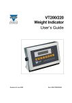
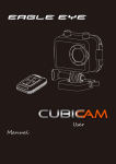
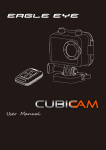
CRY-AC®TrackerCam® INSTRUCTIONS FOR USE www.brymill.com March 2015 Page 1 of 23 TABLE OF CONTENTS Section 1 - Table of Contents Section 1 2 3 4 5 6 7 8 9 10 11 Title Table of Contents Read Before Use Indications For Use 3.1 Use of Content 3.2 Handling Warning 3.3 Warranty CRY-AC®TrackerCam® Introduction 4.1 Package Contents 4.2 Before Use 4.2.1 Battery Installation Instructions 4.2.2 Mini SD Memory Card 4.2.3 Reset Button CRY-AC®TrackerCam® First Time Sep Up Instructions 5.1 Setting the Clock 5.2 Setting the Timeout 5.3 Understanding the Display Functions of the Main Screen 5.4 To Begin Use Recording Process 6.1 Additional Lighting 6.2 Recording Process 6.3 Transferring the Recordings to a Computer Routine Maintenance 7.1 Care & Maintenance 7.2 Cleaning 7.2.1 LCD Display 7.3 Batteries 7.3.1 Battery Replacement 7.3.2 Battery Safety and Disposal Instructions 7.4 Storage 7.5 User Self-Test Troubleshooting 8.1 CRY-AC®TrackerCam® Troubleshooting 8.1.1 Faults Associated to Power 8.1.2 Faults Associated to the Display 8.2 Camera Focus 8.3 CRY-AC® Troubleshooting Technical Specification 9.1 Performance Requirements 9.2 Power 9.3 User Interface 9.4 Operating Modes 9.5 Software 9.6 Camera 9.7 Transport and Storage 9.8 Normal Operating Conditions Chart of Benign Lesions Explanation of utilized Symbols Contact Information Page 2 3 4 4 4 4 5 6 7 7 9 9 10 10 11 12 13 14 14 14 15 16 16 16 16 17 17 17 17 17 18 18 18 19 19 19 19 19 19 19 20 20 20 20 20 21 22 23 Page 2 of 23 INSTRUCTIONS FOR USE Section 2 - READ BEFORE USE CAUTION BEFORE USING THE CRY-AC®TrackerCam® ENSURE YOU HAVE READ THE FOLLOWING INSTRUCTIONS FOR USE - CRY-AC®TrackerCam® INSTRUCTIONS FOR USE - CRY-AC® Keep them in a safe place for future reference This Device is in compliance with 60601-1-2 Instruction for Use in the following languages English German French Italian Dutch Swedish Danish Portuguese Spanish Japanese Can be found and downloaded from the web site at: http://www.brymill.com Page 3 of 23 INSTRUCTIONS FOR USE Section 3 - Indication for Use The CRY-AC®TrackerCam® is a device that measures the temperature of the skin when spraying liquid nitrogen via a CRY-AC®-3 delivery system to the selected skin lesion using the latest infrared censoring technology. It is the physician’s responsibility to decide which skin lesions are to be treated using Liquid Nitrogen since some respond better than others. Published literature and textbooks are available that identify those skin lesions best suited to treatment using Liquid Nitrogen. 3.1 Use Of Content The CRY-AC®TrackerCam® is intended for the use, by a medical professional trained in the use of cryogenic products, for the care of a patient; it is not intended to be used by a non-medical professional. The medical professional is responsible for reviewing and interpreting the images or pictures (or any portions thereof) created by the CRY-AC®TrackerCam®. The CRY-AC®TrackerCam® is not a substitute for the medical or health related advice or diagnosis provided by a medical professional with respect to a health problem or disease of a patient. Such diagnosis is to be made by the medical professional based solely on the medical professional’s examination of the patient. Brymill Cryogenic Systems does not make and specifically negates and disclaims any representations and/or warranties, whether express or implied, oral or written, concerning the use, quality, or condition of such images or pictures, or the duplication thereof. Brymill Cryogenic Systems assumes no responsibility in the manner in which any and all images or pictures created by the CRY-AC®TrackerCam® are used, stored, duplicated, transmitted, or disposed of, either by a medical professional or non-medical person. The user is solely responsible and liable for complying with any and all laws regarding the protection and confidentiality of the images or pictures (or any portions thereof) taken by the CRY-AC®TrackerCam® about a particular patient. 3.2 Handling and Warning Notes The CRY-AC®TrackerCam® contains some components that are very sensitive to vibration or shock, namely the Infrared Sensors and the LCD Display Screen, resulting from improper handling. Brymill Cryogenic Systems have taken every possible precaution to ensure the integrity of these components during manufacturing and delivery. It is therefore the responsibility of the End-user that every effort is made to protect the CRY-AC®TrackerCam® against vibration or shock that could ultimately result in a component failure. Ensure the CRY-AC®TrackerCam® is kept in an upright position at all times when Liquid Nitrogen has been decanted into the Flask and the cover has been replaced. CAUTION: No modification of this equipment is allowed. Any tampering with this device will void the warranty. This unit must be use below 2000 meters. 3.3 Warranty The CRY-AC®TrackerCam® section of the CRY-AC®TrackerCam® is covered by a 1-year limited warranty against manufacturing defects in materials and workmanship. The CRY-AC® section of the CRY-AC®TrackerCam® is covered by the same 3-year warranty defined in the CRYAC® Instructions For Use booklet supplied with each unit. The Charger comes with a 1-year warranty. The Battery comes with a 3 month warranty. These warranties do not cover damage resulting from abuse, neglect improper handling or improper use. Page 4 of 23 INSTRUCTIONS FOR USE 4. CRY-AC®TrackerCam® Introduction Reset (center hole) Touch Screen & Display DC Charging Port On/Off Power and Sleep Button Retaining Screw Microphone The CRY-AC®TrackerCam® Head – Front Display The CRY-AC®TrackerCam® Head - Underside LED Lights Mini SD Card Slot Camera Infrared Sensor Mini USB Port Infrared Beams Left Side Right Side Front The CRY-AC®TrackerCam® is a device that can be used in 1 of 2 ways. Option 1 - By using just the CRY-AC® spray part without the use of the CRY-AC®TrackerCam®. Use without turning the Head section on. Option 2 – By using the full facilities of the CRY-AC®TrackerCam® and record the full treatment process in High Definition video onto a Mini SD memory card. To ensure the best results are obtained when using the full Sensing and Video functions of the CRY-AC®TrackerCam®, and to ensure that the Spray is positioned at the correct focal and working distance for the camera ONLY the supplied 1” x 20g Straight Spray Needle is recommended. The CRY-AC®TrackerCam® is a device that measures the temperature of the skin when spraying Liquid Nitrogen via the CRY-AC® delivery system to the selected skin lesion. In accordance with these Instructions for Use the operator can set the CRY-AC®TrackerCam® to indicate when a predetermined freeze temperature of between 1oC and -70oC has been achieved at the lesion. The CRY-AC®TrackerCam® is a recording device only. It does not have the capability to play back a video recording from the Mini SD Card. To view a recording on the Mini SD Card it must be removed and connected to a computer. To connect, view or transfer a recording on the Mini SD Card refer to the Instructions for Use/User Manual of the device to be used. Page 5 of 23 INSTRUCTIONS FOR USE 4.1 PACKAGE CONTENTS 1 x CRY-AC®TrackerCam® 1 x Rechargeable Custom NiMH Battery (already inserted) 1 x Mini SD Memory Card with Adapter 1 x Charger Unit 2 x 3/4” x 20g Straight Needle Instructions for Use – CRY-AC® CRY-AC-3® Instructions for Use – CRY-AC®TrackerCam® Product Codes to Re-order spares or Replacements Mini SD Memory Card with Adapter Code: TC-SD Replacement Rechargeable Battery Code: TC-BATT Replacement Charger Code: TC-CHARGER 3/4” x 20g Straight Needle Code: 107-20 Available direct from Brymill or from an authorized Brymill dealer. Page 6 of 23 INSTRUCTIONS FOR USE 4. 2 BEFORE USE CAUTION: Do not under any circumstances use any other battery than the one designed for this unit. Doing so could result in damage to the unit. Also, do not under any circumstances use any other charger than the one supplied with the unit. 4.2.1. BATTERY INSTALLATION INSTRUCTIONS The CRY-AC®TrackerCam® is fitted with a custom NiMH rechargeable battery that has been fully charged prior to dispatch but requires final connection and charging as follows. 1. Place the CRY-AC®TrackerCam® onto a firm surface with the spray outlet pointing away from you. Place one hand on the TrackerCam® nose. 2. Place your other hand neat the yellow label attached to the blue and white top assembly. 3. Carefully pull apart (using a slight twist away motion). Use extreme caution not to pull off the internal ribbon cable. 4. Plug the red and black battery cable into the connector located on the bottom right of the ribbon cable. When replacing the battery simply disconnect the battery plug, and remove the battery. Insert a new battery and reconnect the battery plug. Page 7 of 23 5. Now carefully place the upper assembly back into the lower assembly Caution closing. Be aware not to pinch the ribbon cable when 6. Charging The Battery Plug the charger into a 110V-220V electrical power outlet. Plug the supplied charger connector into the DC Charging Port (see picture opposite for Port location) The CRY-AC®TrackerCam® screen will begin to flash indicating the unit is charging. To ensure proper operation, you must leave the unit charging when not in use. (including in between patience). The battery indicator has 5 segments. When all 5 are showing then the battery is deemed to be fully charged. When only 1 segment is showing then the battery requires charging. A fully charged custom NiMH battery provides about 1 hour of continuous operation, with the lights on. Optionally, you may use a USB cable to charge the battery via the mini USB port to your computer. Access to the battery is now only necessary when replacement is required. CAUTION: When charging with a USB cable, the CRY-AC®TrackerCam® must be connected only to the USB port of a computer that complies with the IEC / EN 60950 standard to ensure continued compliance of the product with the European Medical Device Directive. Refer to the operator’s manual provided with your computer to ensure that the computer complies with the above standard. When the battery charge is depleted, the unit will automatically shut off, and will need to be recharged. Note: Safety features within the software have been incorporated to prevent the CRY-AC®TrackerCam® being used with the Charger or Mini USB leads connected. After approximately 500 charges, the battery’s capacity will diminish and the battery may need to be replaced. To replace the battery go to Section 6.3 Access to the battery is now only necessary when replacement is required. Page 8 of 23 INSTRUCTIONS FOR USE 4.2.2. MINI SD MEMORY CARD Your CRY-AC®TrackerCam® is also supplied with a 2gb capacity Mini SD Memory Card and a Card Adapter. The Mini SD Memory Card is inserted into the Card slot on the left side of the CRY-AC®TrackerCam® Head. The Mini SD Memory Card can only be inserted one way. That is with the connectors facing you. Slide the Mini SD Memory Card into the slot and press firmly until you hear the “click”. This indicates the Card is locked in place. To eject the Mini SD Memory Card, wait 10 seconds after video recording has stopped. Failure to wait may result in the loss or corruption of files. Press it in until you hear the “click” and then release it. The Card will eject partly out. Ensure the Card adapter is kept in a safe place, as this may be required to enable the saved video clips to be transferred to a computer. 4.2.3 RESET BUTTON The CRY-AC®TrackerCam® has been designed with a Reset Button. This is located behind the Center Hole of the 3 holes just below the Tracker® Badge. Reset Button Please refer to the Troubleshooting Section to for explanations of when to operate the Reset Button. Page 9 of 23 INSTRUCTIONS FOR USE 5 - CRY-AC®TrackerCam® First Time Set Up Instructions The following is a step-by-step, screen-by-screen process that needs to be applied to use the full functions of the CRY-AC®TrackerCam®. FACTORY SETTINGS Tmin = -1oC Timeout = 300s Clock = North American EST (Eastern Standard Time) or UTC -5 hours Mode = 1 Date = Current Camera Focus – Fixed Press the ON/OFF Power Button twice. There will be 1 audible beep. The following screen sequence will appear. This is the first screen to appear every time the Unit is turned on. After approximately 1 second the screen will go blank. This screen appears after approximately 2-3 seconds. A Blue line also appears in the bottom left of the screen. This indicates that the software is being loaded. As it progresses then the blue line extends to the right of the screen. This takes approximately 10 -15 seconds. This screen will appear when the software has finished loading. The time is displayed on the bottom left and the Battery indicator is displayed on the bottom right of the screen. 5.1 SETTING THE CLOCK AND DATE The clock and date information is part of the information displayed on the screen and also appears in the video clip and therefore is part of the Procedure Record. Touch START Touch MENU This Menu screen appears. Touch CLOCK Page 10 of 23 INSTRUCTIONS FOR USE Touch the Up or Down arrows on the left of the screen to adjust the Hour. Touch the Up or Down arrows in the center of the screen to adjust the Minutes. Touch the AM button to switch to PM. Touch SAVE to save the setting or touch EXIT to cancel changes. Touch DATE Touch the Up or Down arrows on the left of the screen to adjust the Month. The Up or Down arrows in the center of the screen to adjust the Day. The Up or Down arrows on the right of the screen to adjust the Year. Touch SAVE to save the setting or touch EXIT to cancel changes. 5.2 SETTING THE TIMEOUT The Timeout function is the power saving feature of the CRY-AC®TrackerCam® Unit. The Timeout is factory set at 300 seconds which is the maximum time the screen will stay on for if there is no variation to the Actual Temperature. If you want to reduce the Timeout period then follow this process. Touch MENU This Menu screen appears. touch TIMEOUT Touch the Down arrow on the right of the screen to reduce the Timeout period or touch the Up arrows on the left to increase the Timeout period. Touch SAVE to save the setting or touch EXIT to cancel changes. Page 11 of 23 INSTRUCTIONS FOR USE 5.3 Understanding the Display Functions of the Main Screen 1 6 7 2 8 3 9 1. 2. 3. 4. 5. 6. 7. 8. 9. 10. 11. 4 10 5 11 Actual Temperature reading - The Infrared Sensors are constantly recording the temperature Below Tmin - This will display how long temperatures below Tmin were achieved SD Card required – This appears if the Mini SD Card has not been inserted into the Card Slot. REC – Record Button 12:14:40 AM – The actual time of day o Tmin = -10 – Displays the Tmin setting Mode = 1 – Displays the current Mode setting Elapsed – Will display the actual time elapsed between record start and Stop. Light – This button turns the LED Lights on and off. MENU – This button takes you to the main Set Up Screen. Battery – Indicating the battery level. The top of the display is BLUE Your CRY-AC®TrackerCam® Unit is now ready to use. Page 12 of 23 INSTRUCTIONS FOR USE 5.4 TO BEGIN USE Caution: Removing or Inserting the Mini SD Memory Card with the power on may result in the loss or damage of any data stored on the Card. Caution: Do not look directly at the LED lights. If treating facial lesions the Patient must close their eyes and wear suitable non-absorbable eye protection. ® ® 1. Turn the CRY-AC TrackerCam on by pressing the Power Button twice. 2. Ensure you have removed the shipping spray tip plug and attached a 1” x 20g Straight Spray Needle to the ® end of the Delivery Tube of the CRY-AC . 3. Print the patients name and Medical Record Number onto a piece of paper. 4. Using the Table in Section 10 Set Tmin. Touch MENU This Menu screen appears. Touch TMIN Touch the Down arrow on the right of the screen to decrease the Tmin or Touch the Up arrows on the left to increase the Tmin. Touch SAVE to save the setting or Touch EXIT to cancel changes. 5. Set the required MODE MODE 1 - Buzzer beeps once a second as long as <Tmin is achieved. MODE 2, 4 - For future use. MODE 3 - No sound. Touch MENU This Menu screen appears. Touch MODE Touch either Up or Down arrows to scroll to the required Mode. Touch SAVE to save the setting or Touch EXIT to cancel changes. Page 13 of 23 INSTRUCTIONS FOR USE Section 6 – Recording Process 6.1 Additional Lighting Additional Lighting is available by touching the light bulb icon. This can be turned ON or OFF at any time. Touch the Light button if you require additional lighting. When ready Touch REC Lights are now ON 6.2 Recording Processes Point the camera at the paper with the Patients name and pertinent information. Press REC and the Camera will commence the recording process. REC button changes to STOP and the MENU button changes to PAUSE Elapsed time begins counting. Record the Patients information for 2 to 3 seconds then press PAUSE. (When the camera is recording the PAUSE button can be pressed at any time during the procedure. The Elapsed time will continue to count but the Camera is NOT recording). If STOP is pressed at any time this stops the recording process. The Temperature Sensors continue to operate. Reposition the camera and Blue Beams to the lesion to be treated Press RESUME and the camera will continue recording. Focus the 2 Blue beams together to ensure correct focal length and focus. Begin the Freeze Thaw Cycle. Page 14 of 23 INSTRUCTIONS FOR USE The Upper section of the Screen and the 2 Blue Beams change to GREEN when the temperature of the Ice Ball reaches 0oC The Lights have also been turned ON. Continue the Freeze Thaw Cycle. The Upper section of the Screen and the 2 Green Beams change to RED when the temperature of the Ice Ball reaches Tmin. If Mode 1 is set then an Audible Beep will sound every second the RED is maintained. If the Ice Ball temperature goes above Tmin the Screen and Beams will change to GREEN Below Tmin time indicator will also begin. Continue the Freeze Cycle for the require Freeze Time. After the required Freeze time at Tmin has been achieve press STOP. The readings remain in memory until a new recording is started. In the event that the lesion just treated requires a second Freeze Thaw Cycle the camera will automatically begin to record when the beams are refocused on the lesion and the temperature reaches 0oC and below as the freeze begins. 6.3 Transferring the Recording to a Computer To transfer recording on the SD Memory Card to a Computer follow these steps: Ensure the CRY-AC®TrackerCam® Unit is turned off. Eject the Mini SD Card from the side of the CRY-AC®TrackerCam® Head. Insert the Mini SD Card into the Adapter. Insert the Adapter into the appropriate card slot in the computer. Open “Computer” and in Devices with Removable Storage will be a device called CD/MMC. Open the CD/MMC and there will be the video clips currently stored on the Mini SD Memory Card. Transfer/Copy the files to your chosen file location/patient record. If the Mini SD Memory Card is to be used again for new recordings delete the existing files. Eject the Adapter from the computer. Page 15 of 23 INSTRUCTIONS FOR USE Section 7 - Routine Maintenance Caution Before carrying out of the procedures detailed in this section ALWAYS Ensure the CRY-AC® is empty of Liquid Nitrogen. Ensure the Battery Charger or USB Cable is not connected to the CRY-AC®TrackerCam®. Ensure the CRY-AC®TrackerCam® is turned OFF. 7.1 Care and Maintenance Caution Do not drop or subject the CRY-AC®TrackerCam® to strong shocks. The CRY-AC®TrackerCam® has been designed to ensure trouble-free operation. There are no adjustments to be made and there is no special servicing required. During normal use the CRY-AC®TrackerCam® will only require charging the batteries as detailed in section 4.2. 7.2 Cleaning Caution Do NOT immerse the CRY-AC®TrackerCam® in any liquid. Because the CRY-AC®TrackerCam® does not come into contact with the skin, infection risk is classified as LOW. If necessary the plastic case of the CRY-AC®TrackerCam® head and the CRY-AC® Body can be cleaned with a clean damp cloth and soapy water or alcohol wipe. The cloth should only be moist and NOT dripping wet to reduce any risk of water entering the device. Avoid using abrasive cleansers that could scratch and damage the surface of the CRY-AC®TrackerCam®. Also avoid touching or contaminating the optical sensors and light emitting diodes on the front of CRY-AC®TrackerCam®. 7.2.1 LCD (Liquid Crystal Display) Dust, dirt, smears and smudges can result in poor performance of the touch screen functions and therefore should be kept clean at all times. LCD screens or displays are NOT GLASS and should not be cleaned using tap-water & paper towels. Tap-water often includes chemicals like chloride that will leave a residue on the screen. Coarse paper towels or cloths may even scratch and damage the very sensitive LCD. LCD Cleaning Cleaning kits containing the proper cleaning solutions and cloths are available from most retailers of TV’s and Computer products. Use a Microfiber Cloth to remove any obvious dust and gently brush off dirt particles. Never spray cleaning solutions directly onto the screen, spray it into your cleaning cloth. DO NOT press hard onto the cloth when cleaning, let the cleaning solution do its job. Don’t leave any liquid on the screen, remove all the excess moisture as it may damage the screen Let the LCD Screen dry thoroughly before you switch it back on. For hard to remove stains or ink marks you may have to repeat this procedure several times. Don’t apply hard pressure. Page 16 of 23 INSTRUCTIONS FOR USE 7.3 BATTERIES 7.3.1 Battery Replacement Caution – Ensure the CRY-AC® flask is empty of Liquid Nitrogen before carrying out this process. To access the battery compartment you need to remove the CRY-AC®TrackerCam® Display Panel by following the Battery Installation Instructions in Section 4.2.1. 7.3.2 Battery Safety and Disposal Instructions Please follow the instructions below for safe handling and proper disposal of the battery. This symbol on the battery indicates that this product shall not be treated as household waste. The rechargeable NiMh battery from the CRYAC®TrackerCam® can be recycled or disposed of as follows: Dispose or recycle the battery according to the local laws and regulations of your country and region. These regulations are available by simply surfing the internet for “Battery Safety and Disposal”. Batteries may present a risk of fire, explosion, or chemical burn if mistreated. Do not disassemble, puncture, modify, drop, throw, or cause other unnecessary shocks to batteries. Do not dispose of batteries in a fire or trash incinerator, or leave batteries in hot places such as under direct sunlight. Do not store batteries near an oven, stove, or other heat source. Do not connect batteries directly to an electrical source, such as a building outlet or automobile powerpoint. Do not place batteries into a microwave oven, or into any other high-pressure container. Do not immerse batteries in water or otherwise get them wet. Do not touch leaking batteries directly; wear protective material to remove the batteries and dispose of them properly immediately. Do not reverse the polarity (positive and negative terminals) of batteries. Do not mix used and new batteries, or install used batteries in other equipment. Do not charge non-rechargeable batteries, or use unspecified charging instructions or equipment for rechargeable batteries. Do not continue to charge batteries beyond the specified time. Do not give batteries to young children, or store batteries where children may access them. Do not put batteries in mouth. If swallowed, contact physician or local poison control center immediately. 7.4 Storage Always store the CRY-AC®TrackerCam® device in a dry place at temperatures between 40 and 100 degrees (F). Keep CRY-AC®TrackerCam® away from heat, humidity, or harmful chemicals. Avoid direct exposure to sunlight to protect the plastic components. 7.5 User Self-Test Before using the device turn the TrackerCam® Unit on and carry out a simple self-test. When the display is turned on the Temperature Reading in the main box will read Room Temperature. Now focus the 2 blue beams together on the back of your hand. The temperature reading should be 30oC +/- 3oC. Page 17 of 23 INSTRUCTIONS FOR USE Section 8 - Troubleshooting Please check our website (www.brymill.com) for the most current troubleshooting information. The CRY-AC®TrackerCam® does not have any effect on the operation of the CRY-AC®. 8.1 CRY-AC®TrackerCam® Troubleshooting Troubleshooting by an end-user is limited to 2 operations A problem with Power or a problem with the Display functioning. 8.1.1 Faults associated with Power Problem - No or Low Power: The first screen with the Brymill Logo does not appear when the Power button is pressed twice. No audible beep. Battery is fully discharged. Audible beep is heard. Battery is very low on power When switched on Low Battery flashes on and off at the Start Screen. Solution Recharge the Battery. See section 4.2.1 Problem – Charger has been connected but the display now flashes Not Charging. Solution Disconnect the plug from the DC Charging Port and Power down the CRY-AC®TrackerCam®. See section 9.2 Problem - No or Low Power: The battery has been on charge for the required time but charge indicator is showing no green segments. Solution Reset the unit and try recharging. See section 7.1.2 If problem persists replace the battery. See section 6.3.1 If the problem with the CRY-AC®TrackerCam® is not resolved by checking or replacing the battery then the complete device must be returned for repair. Page 18 of 23 INSTRUCTIONS FOR USE 8.1.2 Faults associated with the Display Problem – Display Error: The display is not reading or functioning correctly. Solution If there appears to be a problem with the display or any of the functions of the CRY-AC®TrackerCam® then reset the software by pressing the reset button located behind the center of the 3 holes located under the Tracker badge. This can be done by opening an end of a paperclip and inserting it into the center hole. Caution: do not press hard. Pressing the reset will shut the unit down and will require the double press of the power button to restart it. If the problem with the CRY-AC®TrackerCam® Display or functions is not resolved by doing a Reset then the complete device must be returned for repair. 8.2 Camera Focus The Camera Focus is a Factory Setting and cannot be adjusted by the End User. If the images appear to be outof-focus the complete CRY-AC®TrackerCam® must be returned for repair. 8.3 CRY-AC® Troubleshooting For troubleshooting the CRY-AC® please refer to Section 9 of the CRY-AC® Instructions For Use booklet. However since the Main Valve and Trigger Assembly are now incorporated within the CRY-AC®TrackerCam® housing, if any problems exist relating to a sticking Valve or Trigger, then the complete CRY-AC®TrackerCam® must be returned for repair. The other problems details in Section 9 of the CRY-AC® Instructions For Use booklet relating to intermittent spray or the bottle frosting still apply. Section 9 – Technical Specification 9.1 PERFORMANCE REQUIREMENTS Measurement accuracy better then ±5 oC. Minimum temperature reading -70 oC. Sampling rate greater than 2 Hz Sample area at focus less than 2 mm 9.2 POWER 3.6v 2700mAh Re-chargeable NiMH battery and 5v, 2.1A, Charger. When device is not used for 5 minutes the device goes into Sleep Mode. To exit sleep mode simply press Power button. If device remains in Sleep Mode for 15min the device turns off completely. To turn the CRY-AC®TrackerCam® off at any time, press and hold Power Button for a minimum of 5 seconds. One long and one short beep will be heard. 9.3 USER INTERFACE LCD screen to display ACTUAL TEMPERATURE, Tmin, and TIME AT Tmin. POWER- MODE buttons to turn ON/OFF and select operating MODE. 2 SELECT BUTTONS Function determined by mode and state. Used to scroll through measurements and set SET POINTS LED to identify location of infrared temperature measurement LED color changes as a function of temperature Temp 30 – 0 oC BLUE Temp 0 - Tmin oC GREEN Temp - Tmin oC RED & Below Beep sound to count and indicate when Tmin is achieved. Page 19 of 23 INSTRUCTIONS FOR USE 9.4 OPERATING MODES MODE 1 Display shows Actual temperature reading during use in the large window. Display also shows the total time that Tmin temperature or below was achieved during the freeze cycle. Sound beeps once <Tmin is achieved. MODE 2, 4 (AS MODE 1 except) For future use. MODE 3 (AS MODE 1 except) No sound. 9.5 SOFTWARE Firmware is the software that is running inside the microprocessor on the CRY-AC®TrackerCam®. It controls LED’s and User Button interface. There are no known EMC interference issues. 9.6 CAMERA High Definition (2592H x 1944V), macro video camera 9.7 TRANSPORT AND STORAGE Temperature -40OC to 70OC Humidity 10% - 85% Pressure 70kPa to 106kPa 9.8 NORMAL OPERATING CONDITIONS Temperature +10OC to +35OC Humidity 10% - 75% Pressure 50kPa to 106kPa Page 20 of 23 INSTRUCTIONS FOR USE Section 10 – Chart of Benign Lesions Chart of Benign Lesions with Freeze Times1 and CRY-AC®TrackerCam® Temperatures “This information is only for guidelines and does not pre-empt clinical judgment” Type of Lesion Technique b Freeze time (seconds)* Tmin o Setting C Number a of FTC Margin (mm) Number of treatment sessions Interval (weeks)† Actinic keratosis OS 5 -5 1 1 1 Common warts OS 10 -10 1 2 3 Cutaneous horn OS 10 – 15 -10 1 2 1 Dermatofibroma OS 20 – 30 -15 1 2 2 Hypertrophic scar OS 20 -20 1 2 1 Ingrown toenail ‡ OS 20 -20 1 2 2 8 Keloid OS 20 – 30 -30 1 2 3 8 Myxoid cyst OS 20 -20 1 <1 1 Pyogenic granuloma OS 15 -10 1 <1 1 Skin tags OS 5 -5 1 2 1 Solar lentigo OS 5 -5 1 <1 1 4 8 a FTC = freeze-thaw cycle; OS = Open Spray spot freeze technique * Period of Time to maintain the freeze ball or halo formation at Tmin, not the total spray time. Skin Types I to III. † Interval between repeat treatment sessions. ‡ Target is inflamed granulation tissue, and treatment is helpful in selected cases. b References: Cryosurgery for Common Skin Conditions- M. D. Andrews, MD, Am. Fam. Physician, 2004 May 15;69(10):2365-2372 Liquid Nitrogen: Temperature Control in the Treatment of Actinic Keratosis-L .H. Goldberg & Col. Dermatology Surgery, December 2010, Vol. 26 Number 12 Experience in the use of the Brymill CRY-AC® Tracker for the Treatment of Benign Skin Lesions with Cryosurgery. Eduardo De Carli MD, Argentina Society of Dermatology Page 21 of 23 INSTRUCTIONS FOR USE Section 11 – Explanation of Utilized Symbols The following symbols are used on the device or on the packaging or Instructions for Use: CONSULT INSTRUCTIONS FOR USE CAUTION CE 0120 The CE Mark and 0120 reference indicates that the product complies with the European Medical device Directive 93/42/EEC – Annex II POWER BUTTON – ON/OFF, SLEEP MODE Product bearing this symbol may not be disposed of together with general household waste, but instead requires separate disposal according to local provisions. (European Waste Electrical and Electronic Equipment Directive, WEEE) Serial Number Manufacturer European Authorized Representative Page 22 of 23 World Leader in Design and Manufacture of Cryosurgical Equipment since 1966 Brymill Cryogenic Systems 105 Windermere Avenue, Ellington. CT 06029. USA Tel: (860) 875 2460 In the USA: 1 800 777 2796 Fax: (860) 872 2371 Web: www.brymill.com Email: [email protected] European Authorized Representative Brymill Cryogenic Systems (UK) Ltd Unit 4, Basepoint Centre Stroudley Road Basingstoke RG24 8UP UK Tel: +44 (0)1256 841045 Fax: +44 (0)1256 350330 Email: [email protected] 0120 Page 23 of 23