1
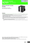
NJ3@, NJ5@ NJ-Series machine controller Complete and robust machine automation The NJ-Series is designed to meet extreme machine control requirements in terms of motion control speed and accuracy, communication, security and robustness. • • • • • • • Integration of logic and motion in one Intel CPU Scalable control: CPUs for 4, 8, 16, 32 and 64 axes EtherCAT and EtherNet/IP ports embedded Fully conforms to IEC 61131-3 standards Certified PLCopen function blocks for motion control Linear, circular and spiral (helical) interpolation CPU units with SQL client and robotic functionality NJ3 CPU NJ5 CPU System configuration NS HMI Sysmac Studio Remote access NJ-Series Machine automation controller Accurax G5 servo drive ADR ADR ADR Up to 100 m Input NX-Series I/O Fast registration inputs, home and limits switches... Accurax G5 servo motors NJ-Series machine controller MX2 inverter FQ-M Vision Accurax linear motors 33 Specifications General specifications Item Enclosure Grounding CPU unit dimensions (H × D × W) Weight Current consumption Operation environment Ambient operating temperature Ambient operating humidity Atmosphere Ambient storage temperature Altitude Pollution degree Noise immunity Overvoltage category EMC immunity level Vibration resistance Shock resistance Battery Life Model Applicable standards NJ@ CPU Unit Mounted in a panel Less than 100 90 mm × 90 mm × 90 mm 550 g (including end cover) 5 VDC, 1.90 A (including SD Memory card and end cover) 0 to 55°C 10% to 90% (with non condensation) Must be free from corrosive gases –20 to 70°C (excluding battery) 2,000 m or less 2 or less: Conforms to JIS B3502 and IEC 61131-2. 2 kV on power supply line (conforms to IEC 61000-4-4.) Category II: Conforms to JIS B3502 and IEC 61131-2 Zone B Conforms to IEC60068-2-6 5 to 8.4 Hz with 3.5 mm amplitude, 8.4 to 150 Hz. Acceleration of 9.8 m/s2 for 100 min in X, Y and Z directions (10 sweeps of 10 min each = 100 min total) Conforms to IEC60068-2-27 147 m/s2, 3 times in X, Y and Z directions (100 m/s2 for relay output units) 5 years at 25°C CJ1W-BAT01 Conforms to cULus, NK, LR and EC directives. Performance specifications (common specifications) Item Processing speed Programming Unit configuration Execution time Ladder diagram instructions (LD, AND, OR and OUT) Math instructions (LREAL) Program capacity*1 Memory Retain attribute*2 capacity for No retain attribute*3 variables Memory for CIO area CJ-Series Work area units (can be Holding area specified with AT specifica- DM area tions for vari- EM area ables.) Maximum number of connectable Units Power OFF detection time Number of expansion racks I/O Capacity Power supply Model to CPU rack AC power supply and expansion racks Motion control Number of controlled axes Maximum number of axes Linear interpolation control Circular interpolation control Number of axes groups Position units Override factors Motion control period Cams Number of cam data points Communications Peripheral USB port Built-in EtherNet/IP port 34 DC power supply Number of cam tables Supported services Physical layer Transmission distance Physical layer Media access method Modulation Topology Baud rate Transmission media Transmission distance Number of cascade connections NJ5@ CPU Unit NJ501-@5@0 1.9 ns min NJ501-@4@0 NJ501-@3@0 26 ns min 20 MB 2 MB 4 MB 6,144 words (CIO 0 to CIO 6143) 512 words (W0 to W511) 1,536 words (H0 to H1535) 32,768 words (D0 to D32767) 32,768 words × 25 banks (E0_00000 to E18_32767) NJ3@ CPU Unit NJ301-1200 3.0 ns min NJ301-1100 42 ns min 5 MB 0.5 MB 2 MB 32,768 words × 4 banks (E0_00000 to E3_32767) Maximum per CPU rack or expansion rack: 10 units Entire controller: 40 units 3 max. 2,560 points max. plus EtherCAT slave I/O capacity NJ-P@3001 Power Supply Unit 30 to 45 ms 22 to 25 ms 64 axes 32 axes 16 axes 8 axes 4 axes 4 axes max. per axes group 2 axes per axes group 32 axes groups max. Pulses, millimeters, micrometers, nanometers, degrees or inches 0.00% or 0.01% to 500.00% Same as process data communications period of EtherCAT communications 65,535 points max. per cam table 65,535 points max. per cam table 1,048,560 points max. for all cam tables 262,140 points max. for all cam tables 640 tables max. 160 tables max. Sysmac Studio connection USB 2.0-compliant B-type connector 5 m max. 10 Base-T or 100 Base-TX CSMA/CD Baseband Star 100 Mbps (100 Base-TX) Shielded, twisted-pair cable (STP): Category 5, 5e or higher 100 m max. (distance between Ethernet switch and node) There are no restrictions if an EtherNet switch is used Machine automation controller Item Communications Built-in EtherNet/IP port CIP message service: Explicit messages CIP service: Tag data links (cyclic communications) Number of connections Packet Interval*4 Permissible communications band Number of tag sets Tag types Number of tags Maximum link data size per node Maximum data size per connection Number of registrable tag sets Maximum tag set size Changing tag data link parameters Multi-cast packet filter*6 Class 3 (number of connections) UCMM (non-connection type) CIP routing Built-in Communications standard EtherCAT port EtherCAT master specifications Physical layer Modulation Baud rate Duplex mode Topology Transmission media Transmission distance Maximum number of slaves Maximum process data size Maximum process data size per slave Communications period Sync jitter Internal clock NJ5@ CPU Unit NJ3@ CPU Unit NJ501-@5@0 NJ501-@4@0 NJ501-@3@0 NJ301-1200 NJ301-1100 32 10 to 10,000 ms in 1.0-ms increments. Can be set for each connection. (Data will be refreshed at the set interval, regardless of the number of nodes.) 1,000 pps*5 including heartbeat 32 Network variables (CIO, Work, Holding, DM and EM Areas.) 8 (Seven tags if controller status is included in the tag set.) 19,200 bytes (total size for all tags.) 600 bytes (note: Data concurrency is maintained within each connection.) 32 (1 connection = 1 tag set) 600 bytes (two bytes are used if Controller status is included in the tag set.) Supported.*2 (when controller is in RUN mode) Supported. 32 (clients plus server) Number of clients that can communicate at one time: 32 max. Number of servers that can communicate at one time: 32 max. Supported. Units through which CIP routing is supported: CS1W-EIP21, CJ1W-EIP21, CJ2H-CPU@@-EIP and CJ2M-CPU3@ IEC 61158, Type 12 Class B (feature pack motion control compliant) 100 Base-TX Baseband 100 Mbps (100 Base-TX) Automatic Line, daisy chain and branching Twisted-pair cable of category 5 or higher (double-shielded straight cable with aluminum tape and braiding) Distance between nodes: 100 m max. 192 Inputs: 5,736 bytes Outputs: 5,736 bytes However, the maximum number of process data frames is 4. Inputs: 1,434 bytes Outputs: 1,434 bytes 500, 1000, 2000 or 4000 s 1000, 2000 or 4000 s 1 s max. At ambient temperature of 55°C: –3.5 to 0.5 min error per month At ambient temperature of 25°C: –1.5 to 1.5 min error per month At ambient temperature of 0°C: –3 to 1 min error per month *1. This is the capacity for the execution objects and variable tables (including variable names). *2. Words for CJ-series units in the holding, DM and EM areas are not included. *3. Words for CJ-series units in the CIO and work areas are not included. *4. Data is updated on the line in the specified interval regardless of the number of nodes. *5. Means packets per second, i.e., the number of communications packets that can be sent or received in one second. *6. An IGMP client is mounted for the EtherNet/IP port. If an Ethernet switch that supports IGMP snooping is used, filtering of unnecessary multicast packets is performed. Performance specifications for CPU units with robotic functionality Item Motion control Robotics Delta robot Number of delta robots NJ5@ CPU Unit NJ501-4500 NJ501-4400 NJ501-4300 3 + 1 (optional rotational axis) axes per robot 8 Delta robots max. (depending on the number of axes supported by the CPU) Performance specifications for CPU units with SQL server Item Programming Memory for CJ-series units (can be specified with AT specifications for variables) NJ5@ CPU Unit NJ501-1520 EM area 32,768 words × 25 banks*1 (E0_00000 to E18_32767) NJ501-1420 NJ501-1320 *1. When the spool function is enabled, the DB connection service uses E9_0 to E18_32767. NJ-Series machine controller 35 Function specifications (common specifications) Item Tasks Programming Function Setup System service times POUs (program organization units) Programs Function blocks Functions Programming languages Variables Types External access of variables Array attribute Array variables Function NJ@ CPU Unit I/O refresh and the user program can be executed in 2 type of tasks: • Primary periodic task: This task has the highest priority. It is always executed in the specified period. There is only one primary periodic task. • Periodic tasks: Periodic tasks are executed during the unused time between executions of the primary periodic task. There can be three periodic tasks. The execution interval and the percentage of the total user program execution time are set for the system services (processes that are executed by the CPU Unit separate from task execution). POUs that are assigned to tasks. POUs that are used to create objects with specific conditions. POUs that are used to create an object that determine unique outputs for the inputs, such as for data processing. Ladder diagrams*1 and structured text (ST). Network variables (the function which allows access from the HMI, host computers or other controllers) An array groups data with the same attributes so that it can be handled as a single unit of data. Number of dimensions: 3 max. Maximum number of elements: 65,535 Maximum size: No restrictions. (They are capacity restrictions to the total data size of variables.) Supported. Array specifications for FB instances Range You can specify a range for a data type in advance. The data type can take only values that specifications are in the specified range. Data types Basic data types BOOL, BYTE, WORD, DWORD, LWORD, INT, SINT, DINT, LINT, UINT, USINT, UDINT, ULINT, REAL, LREAL, TIME (durations), DATE, TIME_OF_DAY, DATE_AND_TIME, and STRING (text strings.) Directive data Direct derivative Structures, unions, enumerations types types Member data Basic data types, structures, unions, enumerations, array variables. types Structures Function A derivative data type that groups together data with different variable types. Number of members: 2,048 max. Nesting levels: 8 max. Number of registered structures: No restrictions. Maximum size: No restrictions. Specifying You can use member offsets to place structure members at any memory locations.*2 member offsets Unions Function A derivative data type that enables access to the same data with different data types. Number of members: 4 max. Member data BOOL, BYTE, WORD, DWORD or LWORD. types Enumerations Function A derivative data type that uses text strings called enumerators to express variable values. Motion control Control modes Position control, velocity control, torque control functions Axis types Servo axes, virtual servo axes, encoder axes and virtual encoder axes Positions that can be managed Command positions and actual positions Single axis Single-axis Absolute Positioning is performed for a target position that is specified with an absolute value. position positioning contol Relative Positioning is performed for a specified position from the command current position. positioning Interrupt Positioning is performed for a specified travel distance from the position where an interrupt feeding input was received from an external input. Single-axis Velocity control Velocity control is performed in position control mode. velocity Cyclic A velocity command is output each control period in the velocity control mode. control synchronous velocity control Single-axis Torque control The torque of the motor is controlled. torque control Single-axis Starting cam A cam motion is performed using the specified cam table. synchronized operation control Ending cam The cam motion for the axis that is specified with the input parameter is ended. operation Starting gear A gear motion with the specified gear ratio is performed between a master axis and slave axis. operation Positioning gear A gear motion with the specified gear ratio and sync position is performed between a master operation axis and slave axis. Ending gear The specified gear motion or positioning gear motion is ended. operation Synchronous Positioning is performed in sync with a specified master axis. positioning Master axis The phase of a master axis in synchronized control is shifted. phase shift Combining The command positions of two axes are added or subtracted and the result is output as the axes command position. Single-axis Powering the The servo in the servo drive is turned ON to enable axis motion. manual servo operation Jogging An axis is jogged at a specified target velocity. 36 Machine automation controller Item Motion control Single axis functions Auxiliary functions for single-axis control Resetting axis errors Homing High-speed homing Stopping Immediately stopping Setting override factors Changing the current position Enabling external latches Disabling external latches Zone monitoring Monitoring axis following error Resetting the following error Torque limit Axes groups Multi-axes coordinated control Auxiliary functions for multi-axes coordinated control Common items Cams Parameters Auxiliary functions Absolute linear interpolation Relative linear interpolation Circular 2D interpolation Axes group cyclic synchronous absolute positioning Resetting axes group errors Enabling axes groups Disabling axes groups Stopping axes groups Immediately stopping axes groups Setting axes group override factors Reading axes group positions Changing the axes in a axes group Setting cam table properties Saving cam tables Writing MC settings Count modes Unit conversions Acceleration/ Automatic deceleration acceleration/ control deceleration control Changing the acceleration and deceleration rates In-position check Stop mode NJ@ CPU Unit Axes errors are cleared. A motor is operated and the limit signals, home proximity signal, and home signal are used to define home. Positioning is performed for an absolute target position of 0 to return to home. An axis is decelerated to a stop. An axis is stopped immediately. The target velocity of an axis can be changed. The command current position or actual current position of an axis can be changed to any position. The position of an axis is recorded when a trigger occurs. The current latch is disabled. You can monitor the command position or actual position of an axis to see when it is within a specified range (zone). You can monitor whether the difference between the command positions or actual positions of two specified axes exceeds a threshold value. The error between the command current position and actual current position is set to 0. The torque control function of the Servo Drive can be enabled or disabled and the torque limits can be set to control the output torque. Linear interpolation is performed to a specified absolute position. Linear interpolation is performed to a specified relative position. Circular interpolation is performed for two axes. A positioning command is output each control period in Position control mode.*2 Axes group errors and axis errors are cleared. Motion of an axes group is enabled. Motion of an axes group is disabled. All axes in interpolated motion are decelerated to a stop. All axes in interpolated motion are stopped immediately. The blended target velocity is changed during interpolated motion. The command current positions and actual current positions of an axes group can be read.*2 The composition axes parameter in the axes group parameters can be overwritten temporarily.*2 The end point index of the cam table that is specified in the input parameter is changed. The cam table that is specified with the input parameter is saved in non-voltage memory in the CPU unit. Some of the axis parameters or axes group parameters are overwritten temporarily. You can select either linear mode (finite length) or rotary mode (infinite length). You can set the display unit for each axis according to the machine. Jerk is set for the acceleration/deceleration curve for an axis motion or axes group motion. You can change the acceleration or deceleration rate even during acceleration or deceleration. You can set an in-position range and in-position check time to confirm when positioning is completed. You can set the Stop Mode to determine when the immediate stop input signal or limit input signal is valid. You can change the input variables for a motion control instruction during execution and execute the instruction again to change the target values during operation. You can specify when to start execution and how to connect the velocities between operations when another motion control instruction is executed during operation. Re-execution of motion control functions Multi-execution of motion control instructions (buffer mode) Continuous axes group motions You can specify the transition mode for multi-execution of instructions for axes group operation. (transition mode) NJ-Series machine controller 37 Item Motion control Auxiliary functions functions Unit (I/O) management Communications Operation management System management functions 38 Monitoring functions Software limits Following error NJ@ CPU Unit The movement range of an axis is monitored. The error between the command current value and the actual current value is monitored for each axis. You can set warning values for each axis and each axes group to monitor them. Velocity, acceleration rate, deceleration rate, torque, interpolation velocity, interpolation acceleration rate, and interpolation deceleration rate Absolute encoder support You can use an OMRON G5-Series Servomotor with an Absolute Encoder to eliminate the need to perform homing at startup. External interface signals The following Servo Drive input signals are used. Home signal, home proximity signal, positive limit signal, negative limit signal, immediate stop signal and interrupt input signal. CJ-Series units Maximum number of units 40 Basic I/O Chattering and Input response times are set. units noise countermeasures Load short-cir- Alarm information for basic I/O units is read. cuit protection and I/O disconnection detection EtherCAT Maximum number of slaves 192 slaves Basic I/O Chattering and Input response times are set. noise countermeasures Peripheral USB port A port for communications with various kinds of support software running on a personal computer. EtherNet/IP Communication protocol TCP/IP, UDP/IP port CIP communi- Tag data links Programless cyclic data exchange is performed with the devices on the EtherNet/IP network. cations service Message CIP commands are sent to or received from the devices on the EtherNet/IP network. communications TCP/IP Socket services Data is sent to and received from any node on EtherNet using the UDP or TCP protocol. applications Socket communications instructions are used. FTP server Files can be read from or written to the SD memory card in the CPU unit from computers at other Ethernet nodes. Automatic clock Clock information is read from the NTP server at the specified time or at specified interval after adjustment the power supply to the CPU unit is turned ON. The internal clock time in the CPU unit is updated with the read time. SNMP agent Built-in EtherNet/IP port internal status information is provided to network management software that uses an SNMP manager. EtherCAT port Process data communications Control information is exchanged in cyclic communications between the EtherCAT master and slaves. SDO communications Control information is exchanged in noncyclic event communications between the EtherCAT master and slaves. SDO communications that are defined in the CANopen standard are used. Network scanning Information is read from connected slave devices and the slave configuration is automatically generated. DC (distributed clock) Time is synchronized by sharing the EtherCAT system time between all EtherCAT devices (including the master). Packet monitoring (only NJ5) The frames that are sent by the master and the frames that are received by the master can be saved. The data that is saved can be viewed with WireShark or other applications. Enable/disable settings for The slaves can be enabled or disabled as communications targets. slaves Disconnecting/connecting Temporarily disconnects a slave from the EtherCAT network for maintenance, such as for slaves replacement of the slave and then connects the slave again. Supported CoE SDO messages that conform to the CANopen standard can be sent to slaves via EtherCAT. application protocol Communications instructions The following instructions are supported: CIP communications instructions, SDO message instructions, no-protocol communications instructions, and protocol macro instructions. RUN output contacts The NJ-P@3001 power supply unit turns ON in RUN mode. Event logs Categories Events are recorded in the following logs: • System event log • Access event log • User-defined event log Maximum number of events per NJ5: 1,024 event log NJ3: 512 Machine automation controller NJ@ CPU Unit Programs, function blocks, functions and global variables can be changed online, individual POUs can be changed by more than worker working across a network. Forced Forced refreshing The user can force specific variables to TRUE or FALSE. refreshing Maximum Device variables 64 number of for EtherCAT forced slaves variables Device variables 64 for CJ-series units and variables with AT specifications MC test Run Motor operation and wiring can be checked from the Sysmac Studio. Synchronization The project file in the Sysmac Studio and the data in the CPU unit can be made the same when online. Data tracing Types Single triggered When the trigger condition is met, the specified number of samples are taken and then tracing trace stops automatically. Continuous Data tracing is executed continuously and the trace data is collected by the Sysmac Studio. trace Maximum number of simultane- NJ5: 4 ous data trace NJ3: 2 Maximum number of records 10,000 Sampling Maximum num- NJ5: 192 variables ber of sampled NJ3: 48 variables variables Timing of sampling Sampling is performed for the specified task period, at the specified time or when a sampling instruction is executed. Data tracing Triggered Triggered traces Trigger conditions are set to record data before and after an event. traces When BOOL variable changes to TRUE or FALSE. Trigger Comparison of non-BOOL variable with a constant. conditions Comparison method: Equals (=), greater than (>), greater than or equals (), less than (<), less than or equals (), not equal (). Trigger position setting: A slider is used to set the percentage of sampling before and after the Delay trigger condition is met. (Example: 20%/80%). Simulation The operation of the CPU unit is emulated in the Sysmac Studio. Maintenance Connection to Connected port Built-in EtherNet/IP port. HMIs Sysmac Studio Connected port Peripheral USB port or built-in EtherNet/IP port. connection Reliability Self-diagnosis Controller Levels Major fault, partial fault, minor fault, observation and information. functions errors Maximum num- 2 ber of message languages User-defined User-defined User-defined errors are registered in advance and then records are created by executing errors errors instructions. Levels 8 levels Maximum num- 9 ber of message languages CPU unit names and serial IDs When going online to a CPU Unit from the Sysmac Studio, the CPU Unit name in the project is Security Protecting software assets compared to the name of the CPU Unit being connected to. and preventing Protection User program You can prevent reading data in the CPU unit from the Sysmac Studio. operating transfer with no mistakes restoration information CPU unit write You can prevent writing data to the CPU unit from the Sysmac Studio or SD memory card. protection Overall project You can use passwords to protect .smc files from unauthorized opening on the Sysmac Studio. file protection Data protection You can use passwords to protect POUs on the Sysmac Studio.*2 Verification of Verification of Online operations are restricted by operation rights to prevent damage to equipment or injuries operation operation that may be caused by operating mistakes. authority authority Number of 5*3 groups Verification of user program The user program cannot be executed without entering a user program execution ID from the execution ID Sysmac Studio for the specific hardware (CPU unit). SD memory Storage type SD memory card (2GB max.), SDHC memory card card functions Application SD memory card operation You can access SD memory cards from instructions in the user program. instructions File operations from the Sysmac You can perform file operations for Controller files in the SD memory card and read/write Studio standard document files on the computer. SD memory card life expiration Notification of the expiration of the life of the SD memory card is provided in a system-defined detection variable and event log. Item Debugging Online editing *1. Inline ST is supported. (Inline ST is ST that is written as an element in a ladder diagram). *2. Supported only by the CPU units with unit version 1.01 or later. *3. When the NJ501 CPU units with unit version 1.00 is used, this value becomes two. NJ-Series machine controller 39 Function specifications for CPU units with SQL server Item Supported port Supported DB Number of DB connections (number of databases that can be connected at the same time) Instruction Supported operations Number of columns in an INSERT operation Number of columns in an UPDATE operation Number of columns in a SELECT operation Number of records in the output of a SELECT operation Run mode of the DB connection service NJ501-1@20 CPU Unit Built-in EtherNet/IP port Microsoft Corporation: SQL Server 2008/2008 R2/2012 Oracle Corporation: Oracle Database 10g/11g 3 connections max.*1 The following operations can be performed by executing DB connection instructions in the NJ-series CPU units. Inserting records (INSERT), updating records (UPDATE), retrieving records (SELECT) and deleting records (DELETE) SQL server: 1,024 columns max. Oracle: 1,000 columns max. SQL server: 1,024 columns max. Oracle: 1,000 columns max. SQL server: 1,024 columns max. Oracle: 1,000 columns max. 65,535 elements max. 4 MB max. Operation mode or Test mode: • Operation mode: when each instruction is executed, the service actually accesses the DB. • Test mode: when each instruction is executed, the service ends the instruction normally without accessing the DB actually. Spool function Used to store the SQL statements when an error occurred and resend the statements when the communications are recovered from the error. Spool capacity: 1 MB*2 Operation log function The following three types of logs can be recorded: • Execution log: Log for tracing the executions of the DB connection service. • Debug log: Detailed log for SQL statement executions of the DB connection service. • SQL execution failure log: Log for execution failures of SQL statements in the DB. DB connection service shutdown function Used to shut down the DB connection service after automatically saving the operation log files into the SD memory card. *1. When two or more DB connections are established, the operation cannot be guaranteed if you set different database types for the connections. *2. Refer to “NJ-Series database connection CPU units user’s manual (W527)” for more information. Nomenclature CPU unit (NJ501/301-@@@@) CPU unit operation indicators Peripheral (USB) port SD memory card connector Built-in EtherNet/IP port operation indicators DIP switch (inside the battery compartment) Built-in EtherNet/IP port Built-in EtherCAT port Battery compartment Built-in EtherCAT port operation indicators 100 to 240 VAC power supply unit (NJ-PA3001) 24 VDC power supply unit (NJ-PD3001) POWER indicator POWER indicator + (DC input) AC input LG – (DC input) Unit connector LG GR GR RUN output RUN output 40 Unit connector Machine automation controller Dimensions NJ-Series system (NJ-P@3001 + NJ501/301-@@@@ + one I/O unit + CJ1W-TER01) No. of units mounted with 31-mm width 90 W 90 Rack width (mm) With NJ501/301-@ 1 205.7 2 236.7 3 267.7 4 298.7 5 329.7 6 360.7 7 391.7 8 422.7 9 453.7 10 484.7 Power supply unit (NJ-PA3001/PD3001) 90 90 70 CPU unit (NJ501/301-@@@@) End cover (CJ1W-TER01) 2.7 90 90 2.7 90 14.7 90 CJ units I/O connector Fujitsu connector MIL connector M3 screw and screwless type connector (140) 2.7 68 (112.5) 90 2.7 W* 65 69.3 65 66.5 65 83.6 65 89 * Refer to the CJ unit tables in the ordering information section for the specific unit width. NJ-Series machine controller 41 Mounting dimensions Mounting height Expansion cable Approx. 100 to 150 mm A 27.5 R 35 R 69 mm 90 27.5 (Units: mm) DIN track model number A PFP-100N2 16 mm PFP-100N 7.3 mm PFP-50N 7.3 mm 90 mm Note: 1. Consider the following points when expanding the configuration: - The total length of I/O connecting cable must not be exceed 12 m. - I/O Connecting cables require the bending radius indicates below. 2. Outer diameter of expansion cable: 8.6 mm. Power supply units current consumption Checking current and power consumption After selecting a power supply unit based on considerations such as the power supply voltage, calculate the current and power requeriments for each rack. Condition 1: Current requirements There are two voltage groups for internal power consumption: 5 V and 24 V. Current consumption at 5 V (internal logic power supply) Current consumption at 24 V (relay driving power supply) Condition 2: Power requirements For each rack, the upper limits are determined for the current and power that can be provided to the mounted units. Design the system so that the total current consumption for all the mounted units does not exceed the maximum total power or the maximum current supplied for the voltage groups shown in the following tables. The maximum current and total power supplied for CPU racks and expansion racks according to the power supply unit model are shown below. Max. current supplied (A) 5-VDC CPU (A) 5-VDC expansion (B) 24 VDC Racks* rack NJ-PA3001 6.0 A 6.0 A 1.0 A NJ-PD3001 6.0 A 6.0 A 1.0 A Power supply Units (C) Max. total power supplied 30 W 30 W Conditions 1 and 2 are below must be satisfied. Condition 1: Maximum current (1) Total unit current consumption at 5 V (A) value (2) Total unit current consumption at 24 V (B) value Condition 2: Maximum power (1) x 5 V + (2) x 24 V (C) value * Including supply to the CPU unit. Note: 1. For CPU racks, include the CPU unit current and power consumption in the calculations. When expanding, also include the current and power consumption of the I/O control unit in the calculations. 2. For expansion racks, include the I/O interface unit current and power consumption in the calculations. Example: Calculating total current and power consumption When the following units are mounted to a NJ-Series CPU rack using a NJ-PA3001 power supply unit. Unit type Model Quantity CPU unit I/O control unit Basic I/O units (input units) NJ501-1500 CJ1W-IC101 CJ1W-ID211 CJ1W-ID231 CJ1W-OC201 CJ1W-DA041 CJ1W-SCU22 Total 1 1 2 2 2 1 1 Basic I/O units (output units) Special I/O unit CPU bus unit Current consumption Voltage group 5V 24 V 1.90 A – 0.02 A – 0.08 A – 0.09 A – 0.09 A 0.048 A 0.12 A – 0.28 A – 1.9 A + 0.02 A + 0.08 A x 0.048 A × 2 2 + 0.09 A x 2 + 0.09 A x 2 + 0.12 A + 0.28 2.84 A (6.0 A 0.096 A (1.0 A 2.84 A x 5 V = 14.2 W 0.096 A x 24 V = 2.3 W 14.2 W + 2.3 W = 16.5 W (30 W Result Total Result Note: 1. For details on unit current consumption, refer to ordering information. 2. CPU rack and expansion rack current consumption and width can be displayed in the Sysmac Studio software by selecting CPU/expansion racks from the configurations and setup in the Multiview Explorer. Power consumption 42 Machine automation controller Ordering information NJ-Series system Sysmac Studio K NS HMI J Remote access H Industrial switching hubbs I Ethernet cable NJ-Series machine automation controller End cover (included with the CPU) A NJ-Series power supply unit B NJ-Series C CPU unit CJ-Series units I EtherCAT cable Accurax G5 servo drive ADR ADR G EtherCAT junction slave MX2 inverter NX-Series I/O FQ-M Vision Accurax linear motors Accurax G5 servo motors NJ-Series expansion racks NJ-Series CPU unit D I/O control unit NJ-Series power supply unit E CPU rack I/O interface unit Units: 10 max. F I/O connecting cable NJ-Series power supply unit Total cable length ≤12 m E OUT IN Expansion rack I/O interface unit NJ-Series power supply unit E II101 Units: 10 max. F I/O connecting cable II101 OUT IN Expansion rack I/O interface unit Up to 3 Expansion racks Units: 10 max. F I/O connecting cable II101 OUT IN Expansion rack NJ-Series power supply unit Units: 10 max NJ-Series machine controller 43 Power supply units Symbol Name A Output capacity 24 VDC Total 1.0 A 30 W 5 VDC 6.0 A 100 to 240 VAC power supply unit for NJ-Series 24 VDC power supply unit for NJ-Series RUN output Model Supported NJ-PA3001 NJ-PD3001 Note: Power supply units for the CJ Series cannot be used as a power supply for a CPU rack of the NJ System or as a power supply for an expansion rack. NJ-Series machine controller CPU units Standard CPU units Symbol Name Program capacity Variables capacity I/O capacity No. of units B NJ501 CPU unit 20 MB 2 MB: Retained 4 MB: Not retained 2,560 points NJ301 CPU unit 5 MB 0.5 MB: Retained 2 MB: Not retained CPU rack: 10 units max. Expansion rack: 40 units max. (Up to 3 expansion racks) Current consumption Number of axes Model 5 VDC 24 VDC 1.90 A – 64 NJ501-1500 32 NJ501-1400 16 NJ501-1300 8 NJ301-1200 4 NJ301-1100 CPU units with robotic functionality Symbol Name Program Variables capacity capacity I/O capacity No. of units B 20 MB 2,560 points CPU rack: 10 units max. Expansion rack: 40 units max. (Up to 3 expansion racks) NJ501 CPU Unit 2 MB: Retained 4 MB: Not retained Current consumption Number Model of axes 5 VDC 24 VDC 1.90 A – 64 NJ501-4500 32 NJ501-4400 16 NJ501-4300 NJ501-4310*1 *1. The NJ501-4310 CPU unit only supports one delta robot. CPU units with SQL client Symbol Name Program Variables capacity capacity I/O capacity No. of units B 20 MB 2,560 points CPU Rack: 10 units max. Expansion rack: 40 units max. (Up to 3 expansion racks) NJ501 CPU Unit 2 MB: Retained 4 MB: Not retained Current consumption Number Model of axes 5 VDC 24 VDC 1.90 A – 64 NJ501-1520 32 NJ501-1420 16 NJ501-1320 Note: The end cover unit CJ1W-TER01 is included with the CPU unit. CJ-Series digital I/O units Symbol Points Type Rated voltage Rated Width Remarks current C AC input 240 VAC 120 VAC 24 VDC 24 VDC 10 mA 7 mA 10 mA 7 mA 24 VDC 24 VDC 24 VDC 24 VDC 24 VDC 24 VDC 24 VDC 24 VDC 250 VAC 250 VAC 7 mA 7 mA 7 mA 4.1 mA 4.1 mA 4.1 mA 4.1 mA 4.1 mA 0.6 mA 2A 250 VAC 2A 8 16 8 16 16 16 16 32 32 32 64 64 8 8 DC input Triac output Relay contact output 16 8 8 16 16 32 32 32 64 64 44 DC output (sink) DC output (sink) 12 to 24 VDC 2 A 12 to 24 VDC 0.5 A 12 to 24 VDC 0.5 A 24 VDC 12 to 24 VDC 12 to 24 VDC 24 VDC 12 to 24 VDC 12 to 24 VDC 0.5 A 0.5 A 0.5 A 0.5 A 0.3 A 0.3 A 31 mm 31 mm 31 mm 31 mm 31 mm 31 mm 31 mm 31 mm 20 mm 20 mm 20 mm 31 mm 31 mm 31 mm 31 mm 31 mm 31 mm 31 mm 31 mm 31 mm 31 mm 31 mm 31 mm 20 mm 20 mm 20 mm 31 mm 31 mm – – – – Current consumption (A) 5 VDC 24 VDC 0.08 – 0.09 – 0.08 – 0.08 – Fast-response (15 s is ON, 90 s is OFF) Inputs start interrupt tasks in PLC program Latches pulses down to 50 s pulse width – – Fast-response (15 s is ON, 90 s is OFF) – – – – 0.13 0.08 0.08 0.09 0.09 0.20 0.09 0.09 0.22 0.09 – – – – – – – – – 0.048 – 0.11 0.096 – – – 0.09 0.10 0.10 – – – Fast-response (15 s is ON, 80 s is OFF) – – Fast-response (15 s is ON, 80 s is OFF) – – 0.15 0.14 0.14 0.22 0.17 0.17 – – – – – – Connection Model type M3 M3 M3 M3 Screwless M3 M3 M3 Fujitsu MIL MIL Fujitsu MIL M3 M3 Screwless M3 Screwless M3 M3 M3 Screwless M3 Fujitsu MIL MIL Fujitsu MIL CJ1W-IA201 CJ1W-IA111 CJ1W-ID201 CJ1W-ID211 CJ1W-ID211(SL) CJ1W-ID212 CJ1W-INT01 CJ1W-IDP01 CJ1W-ID231 CJ1W-ID232 CJ1W-ID233 CJ1W-ID261 CJ1W-ID262 CJ1W-OA201 CJ1W-OC201 CJ1W-OC201(SL) CJ1W-OC211 CJ1W-OC211(SL) CJ1W-OD201 CJ1W-OD203 CJ1W-OD211 CJ1W-OD211(SL) CJ1W-OD213 CJ1W-OD231 CJ1W-OD233 CJ1W-OD234 CJ1W-OD261 CJ1W-OD263 Machine automation controller Symbol Points Type C DC output (source) 8 8 16 32 64 16 + 16 DC in + out (source) 16 + 16 DC in + out (sink) 16 + 16 32 + 32 32 + 32 32 + 32 DC in + out (TTL) Short-circuit protection Short-circuit protection Short-circuit protection Current consumption (A) 5 VDC 24 VDC 0.11 – 0.10 – 0.10 – Short-circuit protection – – – – – – – 0.15 0.17 0.13 0.13 0.13 0.14 0.14 0.19 Rated voltage Rated current Width Remarks 24 VDC 24 VDC 24 VDC 2A 0.5 A 0.5 A 24 VDC 24 VDC 24 VDC 24 VDC 24 VDC 24 VDC 24 VDC 5 VDC 0.3 A 0.3 A 0.5 A 0.5 A 0.5 A 0.3 A 0.3 A 35 mA 31 mm 31 mm 31 mm 31 mm 20 mm 31 mm 31 mm 31 mm 31 mm 31 mm 31 mm 31 mm – – – – – – – – Connection Model type M3 M3 M3 Screwless MIL MIL MIL Fujitsu MIL Fujitsu MIL MIL CJ1W-OD202 CJ1W-OD204 CJ1W-OD212 CJ1W-OD212(SL) CJ1W-OD232 CJ1W-OD262 CJ1W-MD232 CJ1W-MD231 CJ1W-MD233 CJ1W-MD261 CJ1W-MD263 CJ1W-MD563 Note: MIL = Connector according to MIL-C-83503 (compatible with DIN 41651/IEC 60603-1). Symbol CJ-Series analogue I/O and control units Points Type C 4 4 4 8 2 4 4 8 8 Ranges Universal analogue input 0 to 5 V, 1 to 5 V, 0 to 10 V, 0 to 20 mA, 4 to 20 mA, K, J, T, L, R, S, B, Pt100, Pt1000, JPt100 Analogue 0 to 5 V, input 0 to 10 V, –10 to 10 V, 1 to 5 V, 4 to 20 mA High-speed 1 to 5 V, analogue 0 to 10 V, input –5 to 5 V, –10 to 10 V, 4 to 20 mA Analogue 1 to 5 V, input 0 to 10 V, –10 to 10 V, 1 to 5 V, 4 to 20 mA Analogue 0 to 5 V, output 0 to 10 V, –10 to 10 V, 1 to 5 V, 4 to 20 mA Analogue 1 to 5 V, output 0 to 10 V, –10 to 10 V, 1 to 5 V, 4 to 20 mA High-speed 1 to 5 V, analogue 0 to 10 V, output –10 to 10 V Voltage output 1 to 5 V, 0 to 10 V, –10 to 10 V, 1 to 5 V Current output 4 to 20 mA 4+2 Analogue in + out 4 Universal analogue input 2 Process input 4 to 20 mA, 0 to 20 mA, 0 to 10 V, –10 to 10 V, 0 to 5 V, –5 to 5 V, 1 to 5 V, 0 to 1.25 V, 1.25 to 1.25 V Conversion Resolution Accuracy* time V/l: 1/12,000 V: 0.3% 250 ms/4 points 31 mm T/C: 0.1°C I: 0.3% RTD: 0.1°C T/C: 0.3% RTD: 0.3% Universal inputs, with zero/span adjustment, configurable alarms, scaling, sensor error detection Current Connection (A) Model type 5 V 24 V 0.32 – M3 Screwless CJ1W-AD04U CJ1W-AD04U(SL) 31 mm Offset/gain adjustment, 0.42 – peak hold, moving average, alarms M3 Screwless CJ1W-AD041-V1 CJ1W-AD041-V1(SL) M3 CJ1W-AD042 M3 Screwless CJ1W-AD081-V1 CJ1W-AD081-V1(SL) 1/8,000 V: 0.2% I: 0.4% 250 s/point 1/40,000 V: 0.2% I: 0.4% 35 s/4 points 31 mm Direct conversion (CJ2H special instruction) 1/8,000 V: 0.2% I: 0.4% 250 s/point 31 mm Offset/gain adjustment, 0.42 – peak hold, moving average, alarms 1/4,000 V: 0.3% I: 0.5% 1 ms/point 31 mm Offset/gain adjustment, 0.12 0.14 M3 output hold Screwless CJ1W-DA021 CJ1W-DA021(SL) 1/4,000 V: 0.3% I: 0.5% 1 ms/point 31 mm Offset/gain adjustment, 0.12 0.2 output hold CJ1W-DA041 CJ1W-DA041(SL) 1/40,000 0.3% 1/8,000 0.3% 0.40 – M3 35 s/4 points 31 mm Direct conversion (CJ2H special instruction) 250 s/point 31 mm Offset/gain adjustment, 0.14 0.14 M3 output hold Screwless 1/8,000 0.5% 1 to 5 V, 1/8,000 0 to 10 V, –10 to 10 V, 1 to 5 V, 4 to 20 mA DC voltage, 1/256,000 DC current, thermocouple, Pt100/Pt1000, potentiometer NJ-Series machine controller Width Remarks 1/64,000 250 s/point in: 0.2% 1 ms/point out: 0.3% 0.05% 0.05% 0.52 – M3 Screwless 31 mm Offset/gain adjustment, 0.14 0.17 M3 output hold Screwless 31 mm Offset/gain adjustment, 0.58 – M3 scaling, peak hold, Screwless moving average, alarms, output hold 60 ms/4 points 31 mm All inputs individually 0.30 – M3 isolated, configurable alarms, maintenance functions, user-defined scaling, zero/span adjustment 5 ms/point 31 mm Configurable alarms, 0.18 0.09 M3 maintenance functions, user-defined scaling, zero/span adjustment, square root, totaliser CJ1W-DA042V CJ1W-DA08V CJ1W-DA08V(SL) CJ1W-DA08C CJ1W-DA08C(SL) CJ1W-MAD42 CJ1W-MAD42(SL) CJ1W-PH41U CJ1W-PDC15 45 Symbol C Points Type 6 Ranges Temperature K-type (–200 to control loops, 1,300°C) thermocouple J-type (–100 to 850ºC) Temperature Pt100 (–200 to control loops 650°C) Pt1000 (–200 to 650°C) Temperature B, J, K, L, R, control loops, S, T thermocouple Temperature B, J, K, L, R, control loops, S, T thermocouple Temperature Pt100, JPt100 control loops Temperature Pt100, JPt100 control loops 6 2 2 2 2 Resolution Accuracy* Conversion time 0.1°C 0.5% 40 ms/point 0.1°C 0.5% 40 ms/point 0.1°C 0.3% 500 ms total 0.1°C 0.3% 0.1°C 0.1°C Current Connection (A) Model type 5 V 24 V Width Remarks 31 mm Basic I/O unit, 0.22 – setup by DIP switches, adjustable filtering 10/50/60 Hz 31 mm Basic I/O unit, 0.25 – setup by DIP switches, adjustable filtering 10/50/60 Hz 31 mm Open collector NPN 0.25 – outputs M3 Screwless CJ1W-TS561 CJ1W-TS561 (SL) M3 Screwless CJ1W-TS562 CJ1W-TS562 (SL) M3 CJ1W-TC003 500 ms total 31 mm Open collector PNP outputs 0.25 – M3 CJ1W-TC004 0.3% 500 ms total 0.25 – M3 CJ1W-TC103 0.3% 500 ms total 31 mm Open collector NPN outputs 31 mm Open collector PNP outputs 0.25 – M3 CJ1W-TC104 * Accuracy for voltage and current inputs/outputs as percentage of full scale and typical value at 25°C ambient temperature (consult the operation manual for details) Accuracy for temperature inputs/outputs as percentage of process value and typical value at 25°C ambient temperature (consult the operation manual for details) CJ-Series special I/O units Symbol Channels Type C 2 4 Current consumption (A) 5V 24 V 31 mm 2 configurable digital inputs + outputs 0.28 – Target values trigger interrupt to CPU 0.32 – Signal type Width Remarks 500 kHz Counter 24 V, line driver 100 kHz Counter Line driver, 24 V via terminal block Connection type Model Fujitsu 1 × MIL (40 pt) CJ1W-CT021 CJ1W-CTL41-E CJ-Series communication units Symbol Type C Ports Serial communications 2 × RS-232C High-speed units 2 × RS-422A/RS-485 1 × RS-232C + 1 × RS-422/RS-485 EtherNet/IP 1 × 100 Base-Tx – DeviceNet CompoNet PROFIBUS-DP PROFINET-IO RS-422A converter accessory Current consumption (A) 5V 24 V CompoWay/F, host link, 31 mm 0.28 – NT link, Modbus, 31 mm 0.28 – user-defined 31 mm 0.28 – Data transfer Protocols Width Model 9 pin D-Sub 9 pin D-Sub 9 pin D-Sub CJ1W-SCU22 CJ1W-SCU32 CJ1W-SCU42 CJ1W-EIP21*1 0.41 – RJ45 0.29 0.4 – – DP, DPV1 31 mm 0.40 DP 31 mm 0.40 PROFINET-IO control- 31 mm 0.42 ler, FINS/UDP RS-232C to RS-422A/RS-485 signal converter. Mounts directly on serial port – – – 5-p detachable CJ1W-DRM21 4-p detachable CJ1W-CRM21*2 IDC or screw 9 pin D-Sub CJ1W-PRM21 CJ1W-PRT21 RJ45 CJ1W-PNT21 1 × CAN 4-wire, data + power to slaves (Master) 1 × RS-485 (Master) 1 × RS-485 (Slave) 1 × 100 Base-Tx – – EtherNet/IP, UDP, 31 mm TCP/IP, FTP server, SNTP, SNMP DeviceNet 31 mm CompoNet (CIP-based) 31 mm Connection type – – – 9 pin D-Sub to CJ1W-CIF11 screw clamp terminals *1. Supported only by the EtherNet/IP units with unit version 2.1 or later, CPU units with unit version 1.01 or later and the Sysmac Studio version 1.02 or higher. *2. Supported only by the CPU units with unit version 1.01 or higher and the Sysmac Studio version 1.02 or higher. CJ-Series ID sensor units Current consumption (A) Specifications Symbol Type C ID sensor units Connected ID systems V680-Series RFID system No. of connected R/W heads 1 2 External power supply Not required Model No. of unit numbers 5 V 24 V allocated 1 0.26*1 0.13*1 CJ1W-V680C11 2 0.32 0.26 CJ1W-V680C12 *1. To use a V680-H01 antenna, refer to the V680 Series RFID system catalog (Cat. No. Q151) Note: The data transfer function using intelligent I/O commands can not be used. 46 Machine automation controller Expansion Racks CJ-Series I/O control unit (mounted on CPU rack when connecting expansion racks) Symbol Name Connecting cable Connected Unit Width D CS1W-CN@@3 CJ1W-II101 20 mm CJ-Series I/O control unit 5V Current consumption (A) 24 V 0.02 A – Model CJ1W-IC101 Note: Mount to the right of the power supply unit. CJ-Series I/O interface unit (mounted on expansion rack) Symbol Name Connecting cable Width E CS1W-CN@@3 31 mm CJ-Series I/O interface unit 5V Current consumption (A) 24 V 0.13 A - Model CJ1W-II101 Note: Mount to the right of the power supply unit. I/O connecting cables Symbol Name I/O connecting cable F Specifications • Connects an I/O control unit on NJ-Series CPU rack to an I/O interface unit on a NJ-Series expansion rack. or • Connects an I/O interface unit on NJ-Series expansion rack to an I/O interface unit on another NJ-Series expansion rack. Cable length: 0.3 m Cable length: 0.7 m Cable length: 2 m Cable length: 3 m Cable length: 5 m Cable length: 10 m Cable length: 12 m Model CS1W-CN313 CS1W-CN713 CS1W-CN223 CS1W-CN323 CS1W-CN523 CS1W-CN133 CS1W-CN133-B2 EtherCAT junction slave Symbol Name No. of Power supply ports voltage G 3 EtherCAT junction slave 20.4 to 28.8 VDC (24 VDC –15 to 20%) 6 Note: Current consumption (A) 0.08 Dimensions (W x D x H) Weight Model 25 mm × 78 mm × 90 mm 165 g GX-JC03 0.17 48 mm × 78 mm × 90 mm 220 g GX-JC06 Appearance 1. Please do not connect EtherCAT junction slave with OMRON position control unit, Model CJ1W-NC@81/@82 2. EtherCAT junction slave cannot be used for Ethernet/IP and Ethernet. Industrial switching hubs Symbol H Specifications Functions No. of ports Quality of Service (QoS): EtherNet/IP control 3 data priority. 5 Failure detection: Broadcast storm and LSI error 5 detection 10/100 BASE-TX, Auto-Negotiation NJ-Series machine controller Accessories Failure detection No Power supply connector No Yes Power supply connector and connector for informing error Current consumptio Model n (A) 0.22 0.22 0.22 Appearance W4S1-03B W4S1-05B W4S1-05C 47 Recommended EtherCAT and EtherNet/IP communication cables Symbol I Item Ethernet Cat 6a, AWG27, 4-pair cable Standard type patch cable Cable sheath material: LSZH*1 Cable with connectors on both ends (RJ45/RJ45) Manufacturer Cable colour OMRON Yellow Note: This cable is available in yellow, green and blue colours. Green Standard type Cat 5, AWG26, 4-pair cable Cable sheath material: PUR*1 Cable with connectors on both ends (RJ45/RJ45) Cat5, AWG22, 2-pair cable Green Rugged type Cable with connectors on both ends (RJ45/RJ45) Grey Rugged type Cable with connectors on both ends (M12 straight/RJ45) Grey Rugged type Cable with connectors on both ends (M12 L right angle/RJ45) Grey Ethernet installation cable Cat 5, SF/UTP, 4 × 2 × AWG 24/1 (solid core), Polyurethane Weidmüller (PUR) Cat 5, SF/UTP, 4 × 2 × AWG 26/7 (stranded core), Polyurethane (PUR) Connectors RJ45 metallic connector For AWG22 to AWG26 RJ45 plastic connector For AWG22 to AWG24 RJ45 socket DIN-rail mount socket to terminate installation cable in the cabinet Green Cable length (m) 0.2 0.3 0.5 1 1.5 2 3 5 7.5 10 15 20 0.2 0.3 0.5 1 1.5 2 3 5 7.5 10 15 20 0.5 1 1.5 2 3 5 7.5 10 15 20 0.3 0.5 1 2 3 5 10 15 0.3 0.5 1 2 3 5 10 15 0.3 0.5 1 2 3 5 10 15 100 Model XS6W-6LSZH8SS20CM-Y XS6W-6LSZH8SS30CM-Y XS6W-6LSZH8SS50CM-Y XS6W-6LSZH8SS100CM-Y XS6W-6LSZH8SS150CM-Y XS6W-6LSZH8SS200CM-Y XS6W-6LSZH8SS300CM-Y XS6W-6LSZH8SS500CM-Y XS6W-6LSZH8SS750CM-Y XS6W-6LSZH8SS1000CM-Y XS6W-6LSZH8SS1500CM-Y XS6W-6LSZH8SS2000CM-Y XS6W-6LSZH8SS20CM-G XS6W-6LSZH8SS30CM-G XS6W-6LSZH8SS50CM-G XS6W-6LSZH8SS100CM-G XS6W-6LSZH8SS150CM-G XS6W-6LSZH8SS200CM-G XS6W-6LSZH8SS300CM-G XS6W-6LSZH8SS500CM-G XS6W-6LSZH8SS750CM-G XS6W-6LSZH8SS1000CM-G XS6W-6LSZH8SS1500CM-G XS6W-6LSZH8SS2000CM-G XS6W-5PUR8SS50CM-G XS6W-5PUR8SS100CM-G XS6W-5PUR8SS150CM-G XS6W-5PUR8SS200CM-G XS6W-5PUR8SS300CM-G XS6W-5PUR8SS500CM-G XS6W-5PUR8SS750CM-G XS6W-5PUR8SS1000CM-G XS6W-5PUR8SS1500CM-G XS6W-5PUR8SS2000CM-G XS5W-T421-AMD-K XS5W-T421-BMD-K XS5W-T421-CMD-K XS5W-T421-DMD-K XS5W-T421-EMD-K XS5W-T421-GMD-K XS5W-T421-JMD-K XS5W-T421-KMD-K XS5W-T421-AMC-K XS5W-T421-BMC-K XS5W-T421-CMC-K XS5W-T421-DMC-K XS5W-T421-EMC-K XS5W-T421-GMC-K XS5W-T421-JMC-K XS5W-T421-KMC-K XS5W-T422-AMC-K XS5W-T422-BMC-K XS5W-T422-CMC-K XS5W-T422-DMC-K XS5W-T422-EMC-K XS5W-T422-GMC-K XS5W-T422-JMC-K XS5W-T422-KMC-K WM IE-5IC4x2xAWG24/1-PUR Green 100 WM IE-5IC4x2xAWG26/7-PUR – – WM IE-T0-RJ45-FH-BK OMRON – – XS6G-T421-1 Weidmüller – – WM IE-T0-RJ45-FJ-B *1. The lineup features low smoke zero halogen cables for in-cabinet use and PUR cables for out-of-cabinet use. Note: Please be careful while cable processing, for EtherCAT, connectors on both ends should be shield connected and for EtherNet/IP, connectors on only one end should be shield connected. 48 Machine automation controller WE70 FA wireless LAN units Name WE70 FA wireless LAN units Area Europe Type Access point (Master) Client (Slave) 1 set with two antennas, 2.4 GHz/5 GHz Dual-band compatible For TH35 7.5 For TH35 15 5m Directional magnetic-base antenna DIN rail mounting bracket Antenna extension cable Model WE70-AP-EU WE70-CL-EU WE70-AT001H WT30-FT001 WT30-FT002 WE70-CA5M Appearance Note: Special versions are available for USA, Canada, China and Japan. NS HMI Series Symbol Type TFT, 15”, 1024 × 768 pixels J EtherNet TFT, 12”, 800 × 600 pixels TFT, 10”, 640 × 480 pixels TFT, 8.4”, 640 × 480 pixels TFT, 5.7”, 320 × 240 pixels TFT, 5.7”, 320 × 240 pixels STN, Monochrome 5.7”, 320 × 240 pixels Case color Black Silver Black Ivory Black Ivory Black Ivory Black Ivory Black Ivory Black Ivory Model NS15-TX01B-V2 NS15-TX01S-V2 NS12-TS01B-V2 NS12-TS01-V2 NS10-TV01B-V2 NS10-TV01-V2 NS8-TV01B-V2 NS8-TV01-V2 NS5-TQ11B-V2 NS5-TQ11-V2 NS5-SQ11B-V2 NS5-SQ11-V2 NS5-MQ11B-V2 NS5-MQ11-V2 Note: To connect the NJ-Series Controller, NS System version 8.5 or higher is required. CX-Designer version 3.3 or higher is also required. NS HMI Accessories Name Cable Specifications Serial programming cable USB programming cable Video input unit Inputs: 4 channels Signal type: NTSC/PAL Input channels: 2 video channels and 1 RGB channel*1 Signal type: NTSC/PAL Cable to connect NS-CA00_ to video console unit Cable length: 2 m Cable length: 5 m Sheet/cover Anti-reflection sheets (5 surface sheets) Protective covers (5 pack) (anti-reflection coating) Protective covers (1 cover included, transparent) Protective covers (5 covers included, transparent) Attachment adapter Memory card Memory card adapter for PC Replacement battery Chemical-resistant cover (1 cover) NT625C/631/631C-Series to NS12/10-Series NT625C/631/631C-Series to NS12/10-Series (Black) NT610C-Series to NS12/10-Series NT620S/620C/600S-Series to NS8-Series NT600M/600G/610G/612G-Series to NS8-Series 128 MB 256 MB 512 MB – Battery life: 5 years (at 25°C) Model XW2Z-S002 CP1W-CN221 NS-CA001 NS-CA002 NS15 NS12/10 NS8 NS5 NS12/10 NS8 NS5 NS15 NS12/10 NS8 NS5 NS5 F150-VKP (2 m) F150-VKP (5 m) NS15-KBA04 NS12-KBA04 NS7-KBA04 NT30-KBA04 NS12-KBA05 NS7-KBA05 NT31C-KBA05 NS15-KBA05N NS12-KBA05N NS7-KBA05N NT31C-KBA05N NT30-KBA01 NS12-ATT01 NS12-ATT01B NS12-ATT02 NS8-ATT01 NS8-ATT02 HMC-EF183 HMC-EF283 HMC-EF583 HMC-AP001 CJ1W-BAT01 *1. One screen cannot display two videos inputs simultaneously. NJ-Series machine controller 49 NJ-Series options and accessories Specifications SD memory card, 2 GB Model HMC-SD291 DIN track Length: 0.5 m; height: 7.3 mm Length: 1 m; height: 7.3 mm Length: 1 m; height: 16 mm End plate to secure the units on the DIN track (2 pieces are included with the CPU unit and I/O interface unit) PFP-50N PFP-100N PFP-100N2 PFP-M (2 pcs) Battery for NJ-Series CPU unit (The battery is included with the CPU unit) CJ1W-BAT01 End cover (The end cover is included with each CPU unit and I/O interface unit) CJ1W-TER01 Appearance Computer software Symbol K Specifications Sysmac Studio Model SYSMAC-SE2@@@ ALL DIMENSIONS SHOWN ARE IN MILLIMETERS. To convert millimeters into inches, multiply by 0.03937. To convert grams into ounces, multiply by 0.03527. Cat. No. SysCat_I180E-EN-03A 50 In the interest of product improvement, specifications are subject to change without notice. Machine automation controller