1
!"#$%&'($
)*+,$-./0.1$
$
Version 1.1c (Software V3.4 and later)
© 2011-2012, EcoStarter
64-309-46-Manual-GSM_12APlus-Rev1.1c-ENG-CH.docx
!"#$%&'(&)'*!%*!+
IMPORTANT SAFETY INSTRUCTIONS ..................................................................................... 3!
INTRODUCTION ..................................................................................................................... 4!
OPERATING GSM 12A+ .......................................................................................................... 4!
INSTALLATION ...................................................................................................................... 5!
OVERVIEW OF INPUTS AND OUTPUTS .....................................................................................
FIXING ................................................................................................................................
GSM SUBSCRIPTION AND SIM CARD ........................................................................................
PREPARATION OF SIM CARD ...............................................................................................
INSERTION OF SIM CARD ...................................................................................................
CONNECTIONS .....................................................................................................................
GSM ANTENNA ..................................................................................................................
TEMPERATURE SENSORS ....................................................................................................
ALARM DETECTORS ...........................................................................................................
RELAYS ............................................................................................................................
DATA INPUT .....................................................................................................................
POWER SUPPLY .................................................................................................................
5!
5!
6!
6!
6!
7!
7!
7!
7!
8!
8!
8!
POWER-UP ............................................................................................................................ 8!
GSM SIGNAL STRENGTH ........................................................................................................ 8!
REMOTE CONTROL BY SMS .................................................................................................... 9!
OVERVIEW OF COMMANDS ................................................................................................... 10!
ALARM AND SURVEILLANCE COMMANDS ................................................................................. 11!
CONTROL COMMANDS .......................................................................................................... 16!
OTHER COMMANDS .............................................................................................................. 17!
FAQ ..................................................................................................................................... 19!
RESET UNIT TO FACTORY SETTINGS ....................................................................................... 19!
WARRANTY AND COMPLAINTS ............................................................................................ 20!
TECHNICAL SPECIFICATIONS .............................................................................................. 21!
IMPORTANT INFORMATION REGARDING FROST PROTECTION ............................................ 22!
RECYCLING .......................................................................................................................... 22!
RETURN FORM ..................................................................................................................... 23!
2
,-.'/!"*!&+"(%!0&,*+!/1)!,'*+&
•
•
•
•
•
•
•
Read the manual carefully.
Pay attention to all warnings.
Do not expose the unit to water or moisture.
To clean the unit, use a dry cloth and wipe off carefully.
Follow the mounting instructions.
Do only use accessories specified by Sikom.
In case of malfunction do not open the unit or try to repair it. All service must be performed by
authorized service dealers. Contact your local Sikom dealer for more information.
Do NOT expose the unit to water or to wet environments
Water and other liquid can cause malfunctions. The warranty will not cover such damage. The unit is
intended for indoor and dry environments. Should it be accidentally exposed to water, immediately
unplug it and contact your Sikom dealer for inspection.
Do not open the product
In case of malfunction do not open the unit. This will void the warranty.
Mounting
Mount the unit onto a wall or some other firm support.
Avoid humid places.
Do not install the unit nearby heaters or below windows.
Cleaning
GSM 12A+ may be cleaned with a soft cotton or microfibre cloth. Do not use water or other liquid
cleaning agents.
3
,*!/'21)!,'*&
GSM 12A+ is designed for communication over the GSM network. The features include remote control
of 2 appliances, e.g. light and heating, as well as 2 individual alarm inputs and 2 temperature inputs.
The unit can be ordered to switch relays on/off, to detect temperature levels and voltage levels, and to
send alarms by SMS. Typical usage includes switching lights and heating on/off, monitoring
temperatures for frost protection, as well as using detectors for burglary and fire alarm. The unit is
remote controlled by SMS messaging. It can also be controlled locally by means of 2 built-in switches.
'.%/"!,*3&3+-&45"6&
The unit is controlled by SMS. Relay control, status, alarms and settings are easily controlled by SMS
commands. When status information is requested, the unit replies with an easily understandable SMS
containing all current settings. The chapter ‘Controls’ covers this topic.
The unit needs GSM coverage to be able to communicate. If the coverage is bad, we recommend
replacing the enclosed GSM antenna with an external one. Signal strength is shown by a colour LED on
the unit: green means good, whereas red is bad, and no light means no coverage. The signal LED will
flash once approximately every 7 seconds. When the unit receives an SMS, the LED will become green
for 1-2 seconds.
(1/!7%/&,*('/-"!,'*&
For additional information and accessories, please get in touch with your dealer.
Sikom AS and its distributors assume no responsibility for any errors that may appear in this manual.
Information contained herein is subject to change without notice. The latest version of this manual will
always be available on our website.
4
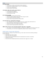
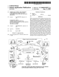
,*+!"$$"!,'*&
&
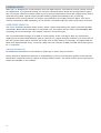
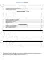
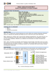
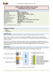
'8%/8,%9&'(&,*.1!+&"*2&'1!.1!+&
7
8
1
1.
2.
3.
4.
5.
6.
7.
8.
2
3
4
5
6
Serial communication port (1)
Temperature sensor inputs
Alarm (detector) inputs
Sense input (*)
Power supply input
Relay outputs
Buttons for local operation of relays and LEDs for the corresponding activation status
GSM signal LED
(,:,*3&
If necessary, fix the unit to a steady and clean support using a double-sided tape.
1
Only for communication with dedicated external equipment (see page 16).
5
3+-&+1#+)/,.!,'*&"*2&+,-&)"/2&
All remote communication with GSM 12A+ takes place over the GSM network. In order to receive SMS
command messages, it needs to have a SIM card installed, just like any standard mobile phone. SIM
cards from most mobile phone operators will do (be they pre-pay or subscription based) as long as
they enable SMS messaging and allow the PIN code to be deactivated.
NB: pre-pay solutions require you to follow up the credit utilization and will usually need to be
recharged with credit at least once a year.
A SIM card is also necessary with Internet-based remote control (we recommend the offer at
my.EcoStarter.com).
./%."/"!,'*&'(&+,-&)"/2&
GSM 12A+ requires the PIN code of the SIM card to be deactivated. This has to be done by temporarily
inserting the SIM card into a normal GSM mobile phone and entering the phone security settings menu
in order to turn off the PIN code of the SIM card. The exact procedure will be described in the manual
of your mobile phone.
NB: if that mobile phone is locked to a given operator, it will not accept the new SIM card unless it
comes from the same operator, even if it's inserted temporarily just for deactivating the PIN code. It
will then be necessary to borrow an appropriate phone instead, or to ask a phone shop to deactivate
the PIN code for you.
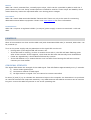
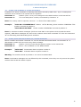
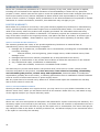
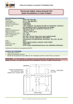
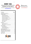
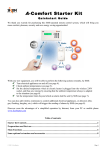
,*+%/!,'*&'(&+,-&)"/2&
Always ensure that the unit is entirely powered off when manipulating the SIM card. Insert the card as
shown below, with the notch in the same corner and the gold contacts facing down. Gently push the
card until it clicks in place. If you later wish to withdraw the SIM card, gently push it inwards until a
click signals that the locking mechanism is open. You may then pull the card out of the slot.
&
Female connector for GSM antenna
6
)'**%)!,'*+&
WARNING: Do not power on before all connections are done.
3+-&"*!%**"&
Try to place the antenna as high as possible in a vertical position.
Please note that the antenna must NOT be placed directly on a metal surface or close to metal items,
as this may block the GSM signal. Any GSM antenna with MMCX connector can be used as long as it
covers the GSM frequencies in use at the operating site.
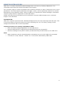
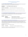
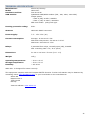
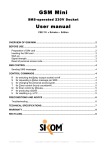
!%-.%/"!1/%&+%*+'/+&
The enclosed temperature sensor is to be connected either to T1 and GND or to T2 and GND. The
actual temperature sensor is located at the tip of the wire.
Temp
sensor
&
R2
R2
R1
R1
GND
+12V
GND
S
I2
I1
GND
T2
T1
GND
RXI
TXU
GSM 12A+ can read temperatures from 2 sensors, e.g. one indoors and the other one outdoors. Please
contact your local dealer to order a second sensor.
Temp
sensor
&
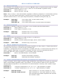
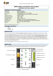
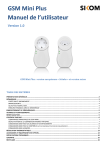
"$"/-&2%!%)!'/+&
GSM 12A+ has 2 digital alarm inputs (I1 and I2) into which usual detectors with standard potentialfree relays may be connected, e.g. smoke, flooding, gas, burglary, or more specialized ones like fault
indicators.
These inputs require a detection loop with a resistor mounted as shown below. The resistor must be in
the range of 10kOhm to 27kOhm. The alarm input is activated whenever the detection loop is either
short-circuited or opened, depending on whether it is mounted as “normally open” (NO), respectively
“normally closed” (NC). For further details, please also refer to the installation instructions enclosed
with the detectors.
NC
C
Resistor
!
Normally closed (NC) detector loop:
Resistor mounted in series with the detector.
NO
R1
GND
+12V
GND
S
I2
I1
GND
T2
T1
R1
GND
+12V
GND
S
I2
I1
GND
T2
T1
&
Resistor
C
Normally open (NO) detector loop:
Resistor mounted in parallel to the detector.
7
/%$"0+&
GSM 12A+ has 2 potential-free, normally open relays, which can be controlled by SMS or with the 2
push buttons on the unit. Relay contact pairs are marked R1 and R2. These relays are bistable, which
means that they retain the requested state even during power outages.
2"!"&,*.1!&
GSM 12A+ has 2 data terminals labelled TXU and RXI. These are only to be used for connecting
dedicated external Sikom equipment. Please visit www.sikom.no for more information.
.'9%/&+1..$0&
GSM 12A+ requires a regulated 12VDC (1A output) power supply. Connect to terminals +12V and
GND.
!
.'9%/;1.&
Once all connections are done and the SIM card (with deactivated PIN code) is inserted, GSM 12A+ can
be powered up.
Turn on the power supply and pay attention to the signal LED on the unit.
• During start-up the Signal LED will become red.
• If the SIM card is missing, or there is another issue with it, the LED will start flashing green
after a few seconds. If this happens, check that the PIN code has actually been deactivated.
• Faults are signalled by 2 short flashes followed by a pause.
• If the LED flashes red, it means that an error has been found during the self-test routines.
Contact your local dealer.
3+-&+,3*"$&+!/%*3!7&
The Signal LED shows the strength of the GSM signal. This LED flashes approximately every 7 seconds.
1) Green means good signal
2) Red means medium to bad signal
3) No light means no signal. The unit cannot be remote controlled.
In cases (2) and (3) try to relocate the antenna to improve the reception. An alternative is to purchase
an external antenna with improved sensitivity. Any GSM antenna with MMCX connector can be used as
long as it covers the GSM frequencies in use at the operating site.!
8
/%-'!%&)'*!/'$�&+-+&
GSM 12A+ is remote controlled by SMS messages sent to it from any ordinary GSM phone. The
commands must follow the scheme described in this chapter.
The unit has a range of control commands. Each command consists of a letter, followed by one or more
parameters. The most frequent parameters are digits 1 and 0, which respectively stand for on and off.
Examples are surrounded by quotes, which are NOT to be reproduced in actual messages. Commands
may be equally written in uppercase or lowercase letters.
Please note that several commands can be combined in the same SMS message up to a maximal
length of 160 characters.
PLEASE NOTE!
GSM 12A+ requires a personal code. All SMS messages sent to the unit must begin with this code. This
is a security feature to prevent anyone else from controlling the unit. The factory setting is 1234.
Change the personal code as soon as possible.
General procedure for sending commands by SMS:
• Enter the SMS messaging application of your GSM phone.
• Start the SMS with the 4-digit personal code followed by the command(s).
• Send the message to the phone number (as determined by the SIM card) of your GSM 12A+.
Note:
• Space characters may be inserted between commands, but not in the middle of a command.
• “1234 R1 S1” is OK, whereas “1234 R 1 S 1” will not be understood by GSM 12A+.
9
'8%/8,%9&'(&)'--"*2+&!"#$!
Alarm and Surveillance Commands
Alarm Recipients
N
O
Store GSM numbers of alarm recipients ........................................................................ 11
Activate an alarm recipient .......................................................................................... 11
Detectors on Inputs I1 & I2
A
B
D
E
Dispatch/acknowledge detector alarms ......................................................................... 12
Activate a new detector .............................................................................................. 12
Define alarm message ................................................................................................ 12
Alarm repetition frequency .......................................................................................... 12
Temperature Surveillance
L
J
F
X
Limits for temperature surveillance .............................................................................. 13
Activate temperature surveillance ................................................................................ 13
Alarm repetition frequency .......................................................................................... 13
Alarm delay (retard) ................................................................................................... 14
Voltage Surveillance
V
G
H
Limits for voltage surveillance ...................................................................................... 15
Activate voltage surveillance ....................................................................................... 15
Alarm repetition frequency .......................................................................................... 15
Relay Control Commands
R
P
T
K
M
Relay activation ......................................................................................................... 16
Produce a pulse activation ........................................................................................... 16
Timer control ............................................................................................................. 16
Engage thermostatic regulation ................................................................................... 16
Target temperatures (set points) for thermostatic regulation ........................................... 16
Other Commands
S
C
!
Y
(*)
Status request ........................................................................................................... 17
Change personal code ................................................................................................ 18
Commentary follows ................................................................................................... 18
Change header text of status message S1 ..................................................................... 18
Available on request: description of commands for modifying hysteresis of thermostatic regulation
(from 1°C to 4°C) and for calibrating voltage measurement.
10
"$"/-&"*2&+1/8%,$$"*)%&)'--"*2+&
1. Alarm Recipients
“N” – STORE GSM NUMBERS OF ALARM RECIPIENTS
Command “N” stores recipients of warnings and alarms issued by GSM 12A+. Up to 9 GSM phone
numbers can be stored in an internal list of recipients.
Parameter 1:
Position (from 1 to 9) to be assigned to the GSM number in the internal list.
Parameter 2:
The new GSM phone number, terminated by character ‘#’.
Note: If a country code is required, insert a ‘+’ in front of the GSM number.
Example:
“1234 N1+47123456789#” Means: +47 for Norway, phone number 123456789. This
number is stored at position 1.
“1234 N3123456789#” Phone number 123456789 is stored at position 3.
Note: In contrast to status messages (which are sent back to the phone which issued the status
request), SMS alarm messages are sent to the numbers stored with command “N”. Also see command
“O” for activating and deactivating these numbers.
“O” – START/STOP SENDING ALARMS TO A GIVEN RECIPIENT
Phone numbers stored with command “N” can be activated and deactivated via command “O”. A
deactivated number will not receive any alarm message.
Parameter 1:
Position (2 to 9) of the relevant phone number in the internal list.
Parameter 2:
Either 1 for ACTIVATE or 0 for DEACTIVATE.
Example:
“1234 O20” Deactivates alarm recipient number 2.
“1234 O31” Activates alarm recipient number 3.
Warning: The number stored at position 1 can never be deactivated.
Note: Usual status messages are not affected by this command, since they are only sent to the phone
number that issued the status request.
11
"$"/-&"*2&+1/8%,$$"*)%&)'--"*2+&
2. Detectors on Inputs I1 & I2
“A” – DISPATCH OR ACKNOWLEDGE DETECTOR ALARMS
Use command “A” to switch ON/OFF the sending of detector alarms by SMS.
Parameter: 0 = OFF, 1 = ON
Example:
“1234 A0”
“1234 A1”
Turns alarms OFF
Turns alarms ON
Note: Surveillance begins 1 minute after the activation command has been received.
Note: Relevant detector inputs must be activated with command B.
You can use command “A0” to acknowledge receipt of a detector alarm and to deactivate the sending
of further alarms. Once the situation is back to normal, you will have to re-enable alarms with
command “A1”.
“B” – ACTIVATE A NEW DETECTOR
Command B is followed by the relevant input number (for I1 or I2) and then 1 for ON or 0 for OFF.
Parameter 1:
Detector input number (1 or 2)
Parameter 2:
0 = OFF, 1 = ON
Example:
“1234 B10” Deactivates detector input I1
“1234 B11” Activates detector input I1
“1234 B21” Activates detector input I2
Note: You normally activate an input only once, when a new detector is connected to GSM 12A+;
it will remain active until you deactivate it explicitly (in case of repair/maintenance work).
“D” – DEFINE ALARM MESSAGE
An alarm SMS message is sent off when the state of a detection circuit changes. The message is
“Alarm x: ” followed by a custom text.
Parameter 1:
Detector input number (1 or 2).
Parameter 2:
Alarm text (no more than 20 characters; it must end with a ‘#’).
Example:
“1234 D1Fire in Garage#”
“1234 D2Water leakage#”
“E” – ALARM REPETITION PERIOD FOR DETECTORS
When a detector triggers an alarm, GSM 12A+ will emit an SMS message. If, after a configurable
duration, the same detector continues to signal an alarm condition, an SMS message will be sent
again. This duration is factory set to 60 minutes, but can be changed to a value from 01 to 99 minutes.
Parameter: Number of minutes (always two digits).
Example:
“1234 E06”
“1234 E25”
Alarms will repeat if needed after 6 minutes.
Alarms will repeat if needed after 25 minutes.
If necessary, use command “A0” to acknowledge receipt of a detector alarm and to deactivate the
sending of further alarms. Re-enable alarms with command “A1”.
12
"$"/-&"*2&+1/8%,$$"*)%&)'--"*2+&
3. Temperature Surveillance
“L” – LIMITS FOR TEMPERATURE SURVEILLANCE
GSM 12A+ can be ordered to monitor the temperature on its two sensor inputs and to send an SMS
message if any of the specified limits are exceeded. Limits can be set between -29 to +49 degrees
Celsius. Temperatures are always written with a ‘+’ or ‘-’ followed by a 2-digits value: “-03” for -3°C,
“+06” for 6°C, etc.
Parameter 1:
Parameter 2:
Parameter 3:
Example:
sensor number (1 or 2).
lower temperature limit (‘+’ or ‘-’ followed by a 2-digits value).
upper temperature limit (‘+’ or ‘-’ followed by a 2-digits value).
“1234 L1-09+20”
Surveillance on input T1 is set to -9°C (lower limit) and +20°C
(upper limit).
Note 1: Command “J” is needed to activate/deactivate temperature surveillance within the given
limits. Phone numbers that shall receive alarms by SMS must be specified using command “N”.
Note 2: If temperature alarms are only wanted for either a lower or an upper limit, just set the other
limit to be so high/low that it will never be reached.
“J” – ACTIVATE TEMPERATURE SURVEILLANCE
Command “J” will activate or deactivate temperature surveillance within the limits specified using “L”.
Parameter 1:
Parameter 2:
Example:
sensor number (1 or 2).
either 1 for activation or 0 for deactivation.
“1234 J10” Deactivates temperature surveillance on input T1.
“1234 J21” Activates temperature surveillance on input T2.
Note: Commands “L” and “J” are often combined as follows:
Example:
“1234 L1-10+20 J11” Temperature surveillance on T1 is turned ON, with levels set to
-10°C and +20°C.
Any resulting alarm message will be sent to the GSM number(s) specified with command “N”.
“F” – ALARM REPETITION PERIOD FOR TEMPERATURE SURVEILLANCE
When a temperature alarm is triggered, GSM 12A+ will emit an SMS message. If the temperature
continues to lie outside the specified limits, an SMS message will be sent again after a configurable
duration. This duration is factory set to 00 minutes, but can be changed to a value from 01 to 99
minutes. A value of 00 minutes will prevent any repetition after the initial message; temperature
surveillance must then be reactivated with command “J11” or “J21”.
Parameter: Number of minutes (always two digits).
Example:
“1234 F09”
Temperature alarms will repeat if needed after 9 minutes.
If necessary, use command “J10” or “J20” to acknowledge receipt of a temperature alarm from sensor
number 1, resp. 2, and to deactivate the sending of further alarms. Re-enable with command “J11”,
resp. “J21”.
13
“X” – ALARM DELAY (RETARD) FOR TEMPERATURE SURVEILLANCE
NB: This requires internal software V3.4TEM
When GSM 12A+ is used for temperature surveillance e.g. of a refrigerator room, overtemperature
must be allowed for a short, configurable duration (opening the door would otherwise almost
systematically trigger an alarm); an alarm will only be triggered if overtemperature persists for this
duration, which is factory set to 00 minutes, but can be changed to a value from 01 to 99 minutes. A
value of 00 minutes sets alarms to be triggered immediately (i.e. within one minute).
Parameter 1:
Parameter 2:
Example:
“1234 X105”
Sensor number (1 or 2).
Number of minutes (always two digits).
Temperature alarms will be triggered at the earliest after 5 minutes of
uninterrupted violation of limits set on sensor 1.
After the initial alarm, messages will be repeated (according to the interval set with command “F”) for
as long as the temperature violation persists uninterruptedly.
14
"$"/-&"*2&+1/8%,$$"*)%&)'--"*2+&
4. Voltage Surveillance
“V” – LIMITS FOR VOLTAGE SURVEILLANCE
GSM 12A+ is able to monitor its +12V power supply input and to send alarms when a given upper or
lower limit is exceeded. Voltages are in the range from 7.5 to 15.0 VDC.
Parameter 1:
Parameter 2:
Lower voltage limit (always a 3-digit value).
Upper voltage limit (always a 3-digit value).
Example: “1234 V095138”
Sets the lower limit 9.5V and the upper limit to 13.8V
Note: Always use 3 digits when specifying a voltage level: e.g. “138” for 13.8V, “095” for 9.5V or
“080” for 8V.
Note: this command will only set surveillance limits; use command “G” to activate the surveillance.
“G” – ACTIVATE/DEACTIVATE VOLTAGE SURVEILLANCE
This command activates or deactivates voltage surveillance within the limits specified with command
“V”. If any voltage limit is exceeded, GSM 12A+ will send an alarm by SMS message.
Parameter: Either 1 for ON or 0 for OFF.
Example:
“1234 G0”
“1234 G1”
“1234 V095138 G1”
Voltage surveillance is turned OFF.
Voltage surveillance is turned ON.
Voltage limits are set to 9.5V (lower limit) and 13.8V (upper
limit), and then voltage surveillance is turned ON.
“H” – ALARM REPETITION PERIOD FOR VOLTAGE SURVEILLANCE
When a voltage alarm is triggered, GSM 12A+ will emit an SMS message. If the voltage continues to lie
outside the specified limits, an SMS message will be sent again after a configurable duration. This
duration is factory set to 00 minutes, but can be changed to a value from 01 to 99 minutes. A value of
00 minutes will prevent any repetition after the initial message; temperature surveillance must then be
reactivated with command “G1”.
Parameter: Number of minutes (always two digits).
Example:
“1234 H06”
Voltage alarms will repeat if needed after 6 minutes.
If necessary, use command “G0” to acknowledge receipt of a voltage alarm and to deactivate the
sending of further alarms. Re-enable with command “G1”.
15
/%$"0&)'*!/'$&)'--"*2+&
“R” – RELAY ACTIVATION
Use command “R” to activate a relay (i.e. to turn it ON/OFF, when in normal manual control) or toggle
between ECONOMY/COMFORT (only on relay 1, when it is in thermostatic regulation mode).
Parameter 1:
Relay number (1 or 2)
Parameter 2:
Either 0 for OFF, 1 for ON
Note: Only on relay 1: when thermostatic regulation is effective, parameter “0” will activate economy
mode (i.e. the lower target temperature, instead of turning the relay off), and parameter “1” will
activate comfort mode (i.e. the upper target temperature, instead of turning the relay on).
Example:
“1234 R11”
“1234 R20”
“1234 R21 S1”
Turns relay 1 ON (or sets comfort mode)
Turns relay 2 OFF
Turns relay 2 ON and then requests status information.
“P” – PULSE ACTIVATION
Command “P” activates a relay for a short time (1 to 9 seconds) and then deactivates it.
Parameter 1:
Relay number (1 or 2)
Parameter 2:
Pulse length in seconds (1 to 9)
Example:
“1234 P11”
“1234 P18”
Activates relay 1 for 1 second
Activates relay 1 for 8 seconds
“T” – TIMER
Relay outputs can be activated for a number of hours (1 to 99 hours).
Parameter 1:
Relay number (1 or 2).
Parameter 2:
Number of hours (always two digits, add a 0 when needed).
Example:
“1234 T102”
Activates relay 1 for 2 hours
“K” – ENGAGE THERMOSTATIC REGULATION
This command activates or deactivates thermostatic regulation on relay output 1. Target temperatures
(“comfort” and “economy”) must be set with command “M”.
Conditions: a temperature sensor is connected on T1/GND, and relay 1 is used to drive the activity of a
heater. Typically, GSM 12A+ is connected to a heater via relay 1 so as to supersede its built-in
thermostat (NB: max. load is 5 Ampere, use an auxiliary relay if necessary).
Parameter :
Either 0 for DEACTIVATE, 1 for ACTIVATE
Example:
“1234 K1”
“1234 K0”
Activate thermostatic regulation.
Deactivate thermostatic regulation.
“M” – TARGET TEMPERATURES (SET POINTS) FOR THERMOSTATIC REGULATION
A lower “economy” and an upper “comfort” target temperature (set points) are set with this command.
When in thermostatic regulation mode, relay output 1 is used to drive a heater so as to reach the
desired ambient temperature. Use command “R” to switch between “economy” and “comfort” target
temperatures.
Parameter 1:
“economy” temperature in °C (a “+” or “-” sign followed by 2 digits).
Parameter 2:
“comfort” temperature in °C (a “+” or “-” sign followed by 2 digits).
Example:
16
“1234 M+05+20”
“1234 M+10+25 K1 R11”
Sets “economy” to +5°C and “comfort” to +20°C.
Sets “economy” to +10°C and “comfort” to +25°C,
then activates thermostatic regulation and requests
the “comfort” mode.
'!7%/&)'--"*2+&
“S” – STATUS REQUEST
This command requests a status message from GSM 12A+. The unit will send the status by SMS back
to the requesting GSM phone (but not to the alarm recipients stored with command “N”). There are 3
kinds of status messages, obtained respectively with commands “S1”, “S2” and “S3”.
Sample status returned by command “S1”:
SIKOM Alarm: OFF Input 1: OFF 2: OFF Rel 1: ON 2:OFF
Temp1:x Temp2:+20
Volt:12.2V N1(12345678) N2(12345678)
Explanations:
SIKOM
Alarm: OFF
Input 1 : OFF 2: OFF
Rel 1:ON 2: OFF
Temp1: x
Temp2: +20
Volt: 12.2V
N1(12345678)
N2(12345678)
Some device identification text (use command “Y” to change this text).
Alarm is not activated.
Detector inputs I1 and I2 are OFF.
Relay 1 is ON, relay 2 is OFF.
No temperature sensor connected on T1.
Temperature measured on T2 is 20°C.
Power supply voltage is 12.2V.
GSM phone number (alarm recipient) at position 1.
GSM phone number (alarm recipient) at position 2.
Sample status returned by command “S2”:
T1:+20 Lim: OFF Lo:-10 Hi:+20
T2: x Lim: OFF Lo:-04 Hi:+15
I1 ready. I2 ready.
Volt: 12.2V Lim: OFF Lo:7.0 Hi:15.0
Term: OFF Lo:+10 Hi:+20
Explanations:
T1:+20
Lim: OFF
Lo:-10
Hi:+20
T2: x
Lim: OFF
Lo:-04
Hi:+15
I1 ready.
I2 ready.
Volt: 12.2V
Lim: OFF
Lo: 7.0
Hi: 15.0
Term: OFF
Lo: +10
Hi: +20
Temperature on sensor T1 is 20°C.
Temperature surveillance on T1 is OFF.
Lower limit for temperature surveillance on T1 is -10°C.
Upper limit for temperature surveillance on T1 is +20°C.
No temperature sensor connected on T2.
Temperature surveillance on T2 is OFF.
Lower limit for temperature surveillance on T2 is -4°C.
Upper limit for temperature surveillance on T2 is +15°C.
Detector on input I1 is vigilant (“ready”), as opposed to “triggered”.
Detector on input I2 is vigilant (“ready”), as opposed to “triggered”.
Power supply voltage is 12.2V.
Voltage surveillance is OFF.
Lower limit for voltage surveillance.
Upper limit for voltage surveillance.
Thermostatic regulation is OFF.
Economy temperature: +10°C.
Comfort temperature: +20°C.
17
Sample status returned by command “S3”:
Request “S3” yields one or two status messages listing all GSM phone numbers stored as recipients of
alarm messages, and if they are active or not.
Num:
N1(…) Active
N2(…)
N3(…)
N4(…)
Temptim: 0 min
Alarmtim: 60 min
Vtim: 0 min
Phone number at position 1, this number is active.
Phone number at position 2.
Phone number at position 3.
Phone number at position 4.
Temperature surveillance: time between each alarm message. (*)
Detector inputs I1 and I2: time between each alarm message. (*)
Voltage surveillance: time between each alarm message. (*)
(*) If the time (repetition interval) is set to 0, any subsequent alarm message will be sent off just
once, and then the related surveillance will be deactivated. This means that no further alarm messages
will be issued before the alarm or surveillance is activated again.
“C” – CHANGE PERSONAL CODE
The default code is “1234”. We recommend that you change this code.
Parameter : The new 4-digit code
Example:
“1234 C5555”
This changes the personal code to 5555. The old code was 1234.
WARNING: Do not lose or forget the new code!
“!” – COMMENTS
This command introduces an optional free-text commentary or explanation of yours. Any text following
the exclamation mark will be ignored by GSM 12A+.
Parameter : The descriptive text
Example:
“1234 R11 ! Switch on living-room heater”
“Y” – INFORMATION TEXT
The header text returned by status command “S1” can be changed with this command to better help
you identify the unit or the appliance(s) controlled or monitored by the unit.
Parameter : The header text (maximum 29 characters; must end with character ‘#’).
Example:
18
“1234 YEquipment No. 3#”
("<&
No signal light:
• Is the power supply connected correctly (polarity)?
• Is the power supply a battery? If so, is it discharged?
• Is there any GSM signal?
• Is the antenna connected?
The Signal LED emits quick green flashes:
• Is the SIM card installed?
• Is the PIN code deactivated?
• Is the SIM card valid?
No contact by SMS:
• Is the GSM coverage good enough?
• Does the battery/power supply provide enough current?
• Is the antenna mounted correctly?
• Do you use the right personal access code?
The unit
•
•
•
•
does not send status messages:
Is it equipped with a pre-pay SIM card? If so, is there any credit left on it?
Has the card been blocked by the network operator?
Check the syntax of your SMS command.
Do you use the right personal access code?
What is the version of the internal software and how to upgrade:
• The version of the internal software is printed on a sticker on the bottom of the unit.
• If necessary, the unit can be upgraded by GSM. Please contact your dealer.
/%+%!&1*,!&!'&(")!'/0&+%!!,*3+&
If you should e.g. forget your personal code, you can reset the unit to its factory settings.
Do the following:
• Disconnect the power supply.
• Press and hold relay button 1.
• Power up the unit and keep the button depressed for at least 10 seconds.
• Release the button.
• The unit is now reinitialized and the personal code is again set to 1234.
19
9"//"*!0&"*2&)'-.$",*!+&
Sikom A.S. provides this publication as is, without warranty of any kind, either express or implied,
including but not limited to the implied warranties of merchantability or fitness for any particular
purpose. Further, Sikom reserves the right to revise this publication and to make changes from time to
time to the content hereof, without obligation to Sikom and its local representatives to notify any
person of such revision or changes. Some jurisdictions do not allow disclaimers of expressed or implied
warranties in certain transactions; therefore, this statement may not apply to you.
$,-,!%2&9"//"*!0&
Each Sikom A.S. product is covered by a two years warranty against any faults due to manufacturing
errors, provided that the product was bought from an authorized Sikom dealer. The warranty is only
valid in the country where the product was originally purchased. For information about warranty
service, please contact your dealer or distributor. The warranty requires the customer to present a
copy of the sales receipt for the original purchase, with place and date of purchase, as well as type of
equipment clearly readable. Please attach a copy of this receipt when requesting a warranty repair.
97"!&,+&)'8%/%2�&!7%&9"//"*!0=&
The warranty protects the owner of the product against any faults due to material flaws or
manufacturing errors, with the following exceptions:
1. Damage due to misfortune, unreasonable use or carelessness (including lack of reasonable and
necessary cleaning).
2.
External factors, such as lightning, power supply issues, mobile network issues, flood
damage or fire.
3. Damages that occurred in transit (complaints are to be presented to the carrier).
4. Damage or deterioration in the surface due to failure to follow the instructions in the manual.
5. Any unauthorized repair, modification or disassembly.
6.
Units with modified, removed or unreadable serial number.
This warranty only covers actual faults in the product itself, which limit or render useless certain
functions described for the product, and does not cover costs related to installing, dismantling
and reinstalling the product, normal setup and adjustments, demands based on inadequate
expectations (possibly due to the seller), or faltering performance due to installation-related conditions
such as sources of radio interferences or power supply issues.
NB: Any repair has to be carried out by Sikom A.S. Unauthorized repair will invalidate the warranty
and be at the owner’s entire risk.
7'9&!'&'#!",*&9"//"*!0&+%/8,)%
Should your Sikom product ever require service, you may return it to your dealer. Remember to use
Sikom’s return form, which you will find at the end of this manual. Please fill it out, and attach a copy
of the original receipt if you require warranty repair.
97'&."0+&('/&+%/8,)%
Sikom A.S. will cover all expenses in manpower and materials for repairs covered by this warranty. If a
necessary repair is not covered by the warranty, or if Sikom does not consider a requested service as a
warranty repair, the owner will have to pay for the repair work or examination. The owner shall pay for
any transport costs to the dealer or directly to Sikom A.S., and Sikom will pay for an economical return
if the repair is covered by the warranty.
20
!%)7*,)"$&+.%),(,)"!,'*+&
Manufacturer:
Model:
Hardware revision:
GSM module:
Sikom AS, Norway
GSM 12A+
300-8011V16
Quadband GSM/GPRS-modem (850 , 900, 1800, 1900 MHz)
Output power:
- Class 4 (2W) at 850 / 900MHz
- Class 1 (1W) at 1800 / 1900MHz
SIM-card holder: push/push type.
Housing protection rating:
IP20.
Antenna:
GSM with MMCX connector.
Power Supply:
7.5 – 15.0 V DC (1A).
Current consumption:
Average: 20 mA at 12 V DC.
With both relays active: 32 mA at 12 V DC.
Maximum: 68 mA at 12 V DC.
Relays:
2 potential-free relays, normally open (NO), bistable.
Max. switching load: 5 A / 30 V (each).
Dimensions:
21 mm x 106 mm x 70 mm (D x L x H)
Weight:
105 g
Operating temperature:
Storage temperature:
Humidity:
– 20 to +40 °C
– 30 to +50 °C
< 93 % RH
GSM 12A+ is designed for indoor use only.
This equipment complies with the European R&TTE directive. Further information may be obtained by
contacting either www.EcoStarter.com, or your local dealer or the manufacturer:
Sikom AS
Neptunveien 6
7650 Verdal
Norway
Internet address: www.sikom.no
21
,-.'/!"*!&,*('/-"!,'*&/%3"/2,*3&(/'+!&./'!%)!,'*&
!
The thermostatic regulation function offered by Sikom devices may be used to maintain a base “eco”
temperature in your premises, but must not be taken as an infallible frost protection.
Indeed, any electronic equipment is vulnerable to power surges and other perturbations that may
come from the electricity network, e.g. due to lightning. In such an event, if the electronics is
damaged, it may no longer ensure the thermostatic regulation, and hence the frost protection.
Therefore, if frost protection is a critical requirement (such as around water pipes), it is recommended
to add a security mechanism. These are some alternatives:
1. Use an additional heating system, with its own thermostat, to ensure frost protection in critical
premises.
%&
Install a protection against power surges and other perturbations from the electricity network.!
'&
Set up a bimetal thermostat in parallel with your Sikom unit.!
Sikom and its representatives will not assume liability for any damage due to frost!
/%)0)$,*3&
The WEEE (Waste Electrical and Electronic Equipment) symbol indicates that this product must not be
disposed of along with other household waste. It is the customer's responsibility to dispose of the
product properly by taking it to a designated site for recycling. To locate a recycling/disposal site near
you, contact your local city recycling program, your regular waste disposal service or the agent from
whom you purchased this product.
In Switzerland, this product includes in its purchase price a contribution (the advanced recycling fee) to
the SWICO Recycling Warranty, which means that used equipment can be handed in free of charge for
recycling. Collection sites are listed at this address: http://www.swicorecycling.ch
&
22
/%!1/*&('/-&
Company name:
Contact person:
Address:
ZIP/City
Invoice/order number:
Client number:
Phone:
E-mail:
!
RETURN NUMBER:
!
Before returning a product, always ask for a return number. This will be given to you by our support
department.
Request for advanced replacement unit (please tick)
Yes
No
A copy of the receipt for the original purchase is included
Yes
No
Warranty service requires the customer to present a copy of the sales receipt for the original purchase,
with place and date of purchase, as well as type of equipment clearly readable. Please attach a copy of
this receipt when requesting a warranty repair.
Return codes: (to be used in the following grid)
1.
2.
3.
4.
Error by seller or order recipient
Ordering error by customer
Wrong delivery from warehouse
Complaint / warranty repair
Art. number
Product name
Quantity
5.
6.
7.
Return
code
Other problem (please specify)
Return of demo equipment
Return of advanced replacement products
Reason for return
Remarks:
Reserved for Sikom AS:
Date:
Signature:
Sikom AS ! Neptunveien 6 ! 7650 Verdal ! Norway
Phone: +47 74 08 59 60 ! Fax: +47 74 08 59 70 ! www.sikom.no
23