1
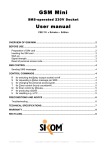
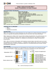
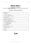
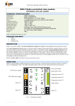
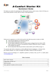
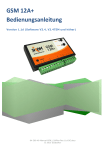
64-309-46_001-Manual-GSM_12A_Rev1.4-ENG-CH.doc
Page 1
GSM 12A
SMS-operated Alarm and Switch Control
Installation and User Manual
www.EcoStarter.com
OVERVIEW OF GSM 12A
TABLE OF CONTENTS:
OVERVIEW OF GSM 12A .............................1
INSTALLATION.............................................2
Preparation of SIM card ...........................2
Inserting the SIM card..............................2
Connections required before use .............2
Antenna ...................................................2
Temperature sensors...............................2
Alarm detectors .......................................3
Relay contacts .........................................3
DATA connectors ....................................3
Power supply ...........................................3
LEDs for status of relay (or switch, or output):
• Green light: relay on
• No light: relay off
Push buttons for local control of relays
Antenna connector
START-UP.....................................................3
Powering on GSM 12A ............................3
Signal strength.........................................3
Identification of optional keyboard............3
SMS CONTROL ............................................4
Introduction..............................................4
Sending SMS messages .........................4
Overview of SMS commands...................4
List of SMS commands ............................4
TROUBLESHOOTING...................................7
PRECONDITIONS AND ADVICE ..................7
TECHNICAL SPECIFICATIONS....................8
WARRANTY ..................................................9
Alarm LED
RECYCLING..................................................9
Alarm detector inputs I1 and I2
2 relays, rated at 16 A / 50 VDC
R
Data connectors for AGG-3 extension
Temperature inputs T1 and T2
Signal strength LED
64-309-46_001-Manual-GSM_12A_Rev1.4-ENG-CH.doc
Page 2
INSTALLATION
Preparation of SIM card
All remote communication with GSM 12A takes
place through the GSM network. In order to receive
SMS command messages, GSM 12A needs to
have a SIM card installed, just like any standard
mobile phone. SIM cards from any mobile phone
operator will do (pre-pay or subscription based) as
long as they enable SMS messaging.
NB: pre-pay solutions will often have a limited life
span, and need to be recharged with credit at least
once a year.
GSM 12A requires the SIM card PIN code to be
deactivated. This is carried out by temporarily
inserting the SIM card into a normal GSM mobile
phone where the PIN code can be turned off
(please refer to the manual of your mobile phone).
Connections required before use
NB: do not connect the power supply
before all connections are made!
Use a flat-head screwdriver to lift the contact
springs of the terminal block while inserting the
wires into their terminal points.
Wire
Flat-head
screwdriver
Inserting the SIM card
Always ensure that GSM 12A is turned off when
manipulating the SIM card. Insert the card as
shown below, with the notch in the top right corner.
Antenna
Hang the antenna vertically, as high as possible,
on a wood or plaster support.
For the actual connection, please refer to the
overview, page 1.
Temperature sensors
Connect the enclosed temperature sensor either on
inputs T1 and GND, or on T2 and GND. Locate the
sensor tip where temperature reading is wanted
(but protect it from excessive humidity). You may
purchase a second sensor for monitoring two
locations.
Temp
Temp
To preserve their precision, temperature sensors
should be laid out so as to avoid electrical
interference, e.g. from 230 V cables or floor
heating.
64-309-46_001-Manual-GSM_12A_Rev1.4-ENG-CH.doc
Page 3
Alarm detectors
GSM 12A offers 2 inputs for gas, fire, intrusion,
water or similar detectors. Connect such detectors
either on inputs I1 and GND, or on I2 and GND. A
resistor of any value from 10 kOhm to 27 kOhm
must be inserted as shown in the following two
figures. This resistor allows connecting any
“all-or-nothing” detector, be it normally open or
normally closed.
NC
Resistor
C
Normally closed (NC) detector loop:
resistor mounted in series
START-UP
After all required connections have been made and
a SIM card inserted, follow the start-up procedure:
Powering on GSM 12A
Once GSM 12A has been connected to a 12 VDC
power supply, it will be ready in 10 to 15 seconds.
The Signal LED will light up according to the
convention described below under the title Signal
strength.
Should there be a problem with the SIM card (e.g.
if it has been incorrectly inserted, if the SIM card is
faulty, or its PIN code not deactivated), the Signal
LED will start blinking green after a few seconds. In
that case, first make sure that the SIM card PIN
code really is deactivated, as described on page 2.
If Alarm LED keeps blinking red, a fault was
discovered during the self-test of GSM 12A. This
indication occurs about 20 seconds after powering
on. Contact then your dealer.
Signal strength
NO
Resistor
C
Normally open (NO) detector loop:
resistor mounted in parallel
Relay contacts
GSM 12A integrates 2 potential-free 16 A relays
(max 50 V), which are controlled by sending SMS
messages or by operating the push-buttons on the
faceplate of the device. Connect the load to the
relays through terminals NO (for normally open)
and C (for common).
DATA connectors
GSM 12A has two data connectors labelled DATA
A and DATA B, to be used only with extension
AGG-3, a power generator controller made by
Sikom. The user manual of AGG-3 describes these
connectors.
Power supply
Connect power supply wires to terminals +12V and
GND. The 12 volts source must be able to deliver
at least 1 ampere.
The Signal LED indicates signal strength as
follows:
Steady green:
good signal.
Off (no light):
bad or no signal.
In case situation (2) occurs, try re-orienting the
antenna to obtain a better coverage. Failing that, a
better antenna may be purchased from Sikom.
Identification of optional keyboard
The wireless keyboard is an optional accessory
that is only used for switching the alarm on/off
while being on site. Prior to use, GSM 12A must
learn the radio ID of the keyboard, following the
procedure below; this has to be done only once.
First, press both push-buttons of GSM 12A until the
LEDs start blinking. Then keep the “S” and “A” keys
of the wireless keyboard depressed until keyboard
LEDs start flashing alternatively red and green,
which signals that the keyboard has been
successfully identified by GSM 12A.
Use the keyboard as follows: press “A”, wait until
the LED stops blinking, then type your personal
access code. Possible outcomes:
Green blinking:
Red blinking:
alarm deactivated.
alarm activated.
64-309-46_001-Manual-GSM_12A_Rev1.4-ENG-CH.doc
Page 4
SMS CONTROL
Introduction
GSM 12A is configured and controlled using regular
SMS messages sent from mobile phones.
The factory-set “1234” personal access code will be
used in the following examples. You should set a
new access code as soon as possible – and
remember it !
Sending SMS messages
SMS messages must always contain the following:
• First, the 4-digit access code.
• Then, any configuration/control commands
(possibly several of them per SMS).
“” (quotation marks) are not part of the SMS.
Address SMS messages to GSM 12A by using the
phone number of the SIM card inside it.
Overview of SMS commands
Alarm on or off
Activate / deactivate alarm detectors (inputs
I1 and I2)
D = Set alarm text
R = Switch relay on or off
S = Status message
T = Timer control
C = Change personal access code
L = Limits for temperature surveillance
J = Activate temperature surveillance for the
limits set with command “L”
N = Mobile number to which GSM 12A will send
surveillance and alarm messages.
V = Limits for power supply voltage surveillance
(between 7 and 15 volts)
G = Activate voltage surveillance for the limits set
with command “V”
List of SMS commands
A
Alarm on/off
A is followed by 1 for on, or 0 for off.
E.g.: “1234 A1” switches on alarm (surveillance of
inputs I1 and I2)
E.g.: “1234 A0” switches off alarm (surveillance of
inputs I1 and I2)
NB: Remember to activate inputs via command “B”.
B
Activate / deactivate alarm inputs
B is followed by detector input number, then 1 for
on or 0 for off.
E.g.:
E.g.:
E.g.:
E.g.:
“1234
“1234
“1234
“1234
B11”
B10”
B21”
B20”
activates detector on input I1
deactivates detector on input I1
activates detector on input I2
deactivates detector on input I2
A=
B=
The space character may be used between
commands, but not inside a command:
“1234 R1 S1” is valid, but “1234 R 1 S 1”
will not be understood.
D
Set alarm text
D is followed by detector input number and text
message (max 20 characters). End with the “#”
character.
E.g.: “1234 D1Fire in dormitory#”
E.g.: “1234 D2Water leak#”
R
Relay on/off
R is followed by relay number, then 1 for on or 0 for
off.
E.g.:
E.g.:
E.g.:
E.g.:
“1234
“1234
“1234
“1234
R11”
R10”
R21”
R20”
switches on relay 1
switches off relay 1
switches on relay 2
switches off relay 2
S
Status message
There are two kinds of status messages. When
GSM 12A receives command S1 or S2, it will send
the corresponding status message to the mobile
phone number the command was received from.
E.g.: “1234 S1” or “1234 S2”
E.g.: “1234 S1 S2” yields two SMS messages
64-309-46_001-Manual-GSM_12A_Rev1.4-ENG-CH.doc
Status message for command S1
S1 returns an overview of the most important
configuration settings.
Sample status message received with S1:
Alarm:OFF Input 1:OFF 2:OFF
Relay 1:ON 2:OFF Temp1:X Temp2:+20
Volt:12.2V Num:(12345678) GSM12A V1.0E
Explanation:
Alarm:OFF (Alarm is not activated)
Input 1:OFF 2:OFF (Detector inputs I1 and I2
are deactivated)
Relay 1:ON 2:OFF (Relay 1 is on, relay 2 off)
Temp1:X (Temperature sensor T1 not connected)
Temp2:+20 (Current temperature at sensor T2)
Volt:12,2V (Voltage of power supply)
Num:(12345678) (Number to which surveillance
and alarm messages are sent)
GSM12A V1.00 (Software version of GSM 12A)
Status message for command S2
S2 returns the details of surveillance-related
configuration settings.
Sample status message received with S2:
T1:+20 Lim:OFF Lo:-10 Hi:+20
T2:X Lim:OFF Lo:-04 Hi:+15
Volt: 12,2V Lim:OFF Lo:7,0 Hi:15,0
Num:(12345678) GSM12A V1.0E
Explanation:
T1:+20 (Current temperature, sensor T1)
Lim:OFF (Temperature surveillance off for T1)
Lo:-10 Hi:+20 (Chosen lower and upper limits
for temperature surveillance at T1)
T2:X (Temperature sensor T2 not connected)
Lim:OFF (Temperature surveillance off for T2)
Lo:-04 Hi:+15 (Chosen lower and upper limits
for temperature surveillance at T2)
Volt:12,2V (Voltage of power supply)
Lim:OFF (Voltage surveillance is off)
Lo:7,0 Hi:15,0 (Chosen lower and upper limits
for voltage surveillance)
Num:(12345678) (Number to which surveillance
and alarm messages are sent)
GSM12A V1.0E (Software version of GSM 12A)
Page 5
T
Timer control
The built-in relays can be turned on for a
programmable duration, between 1 and 99 hours.
T is followed by relay number, then the desired
number of hours (always a 2-digit value: “01” = 1
hour, “05” = 5 hours, etc.)
E.g.: “1234 T101” switches relay 1 on for 1 hour
“1234 T222” switches relay 2 on for 22 hours
C
Change personal access code
C is followed by a new 4-digit personal access
code. The factory-set “1234” code should be
replaced as soon as possible.
E.g.: “1234 C9898” changes code from 1234 to 9898
NB: remember the new code!
L
Limits for temperature surveillance
GSM 12A is able to perform temperature
surveillance and send an SMS message when a
chosen lower or upper limit is exceeded.
The chosen limits must be in the range of
-29ºC to +49ºC.
First, remember to set with command “N” the
number to which these alarms shall be sent.
Use command “J” to activate or deactivate
surveillance of chosen temperature limits.
Once any of the limits is exceeded, GSM 12A will
send off a message, and deactivate the
surveillance. If you wish to continue the
surveillance, re-activate it with command “J”.
L is followed by sensor number, then the lower and
upper limits. Temperatures are 2-digit values
preceded by “+” or “-”, as in “+05”, “+22”, “-09”, “20”.
E.g.: “1234 L1-10+20” stores -10ºC and +20ºC as
lower and upper limits for sensor T1
E.g.: “1234 L2-08+05” stores -8ºC and +5ºC as
lower and upper limits for sensor T2
Should you want surveillance of only one limit, set
the other limit low or high enough to ensure that it
will never be exceeded.
64-309-46_001-Manual-GSM_12A_Rev1.4-ENG-CH.doc
J
Activate temperature surveillance
for the limits set with command “L”
J is followed by sensor number, then 1 for on or 0
for off.
E.g.: “1234 J11” activates surveillance on sensor T1
E.g.: “1234 J20” deactivates surveillance on T2
GSM 12A will send resulting SMS messages to the
mobile phone number stored with command “N”.
NB! Once any of the limits is exceeded, GSM 12A
will send off an SMS message, and deactivate the
surveillance. If you wish to continue the
surveillance, re-activate it later (as in the first above
example) when the temperature has come back to
normal.
Commands “L” and “J” may be combined.
E.g.: “1234 L1-10+20 J11” stores -10ºC and +20ºC
as lower, respectively upper limits for sensor T1,
then activates surveillance on sensor T1.
Phone number for surveillance and
alarm messages
GSM 12A needs to know to which number it is to
send its surveillance and alarm messages. In
contrast, simple status messages will be returned
as replies directly to the phone, which sent the
request (command “S”).
Page 6
V
Voltage surveillance limits
GSM 12A is able to monitor the tension of its power
supply (usually a 12V battery), and send an SMS
message when a chosen lower or upper voltage
limit is exceeded. The chosen limits must be in
the range of 7V to 15V.
NB! Remember to set with command “N” the
number to which these alarms shall be sent.
Use command “G” to activate surveillance of
chosen voltage limits. Once any of the limits is
exceeded, GSM 12A will send off an SMS
message, and deactivate the surveillance. If you
wish to continue the surveillance, re-activate it with
command “G”.
V is followed by the lower, then the upper voltage
limits (always written as 3-digit values: “095” =
9.5V, “138” = 13.8V, etc.).
E.g.: “1234 V095138” sets lower limit to 9.5V (095),
and upper limit to 13.8V (138).
E.g.: “1234 V075125” sets lower limit to 7.5V (075),
and upper limit to 12.5V (125).
N
E.g.: “1234 N12345678#” stores 12345678 as
number for receiving surveillance and alarm SMS
messages.
Always end the number with a “#” (sharp).
It is recommended to immediately verify the
correctness of the entered number (command
“S1”).
E.g.: “1234 N12345678# S1” stores a new number
and requests a status message for verification.
Do not forget the international dialling code if GSM
12A is to send messages to phones with a foreign
SIM card (e.g. prefix +47 for Norway, +41 for
Switzerland, etc.).
E.g.: “1234 N+41123456789#” stores a Swiss
number
G
Activate voltage surveillance for limits
set with command “V”
G is followed by 1 for on, or 0 for off.
E.g.: “1234 G1” activates voltage surveillance
E.g.: “1234 G0” deactivates voltage surveillance
GSM 12A will send resulting SMS messages to the
mobile phone number stored with command “N”.
NB! Once any of the limits is exceeded, GSM 12A
will send off an SMS message, and deactivate the
surveillance. If you wish to continue the
surveillance, re-activate it later (as in the first above
example) when the voltage has come back to
normal.
Commands “V” and “G” may be combined.
E.g.: “1234 V095138 G1 S2” sets lower limit to 9.5V
(095), upper limit to 13.8V (138), then activates
voltage surveillance (command “G1”), and finally
requests a status message (command “S2”) to
check the correctness of the specified values.
64-309-46_001-Manual-GSM_12A_Rev1.4-ENG-CH.doc
TROUBLESHOOTING
No light from any LED:
• Are the wires mounted correctly (polarity) to
terminals +12V and GND?
• Does the battery/power supply provide enough
current?
• Is the GSM network coverage sufficient?
• Is the antenna connected?
Signal LED rapidly blinks green:
• Is the SIM card inserted?
• Is the SIM card PIN code deactivated?
• Is the SIM card subscription valid?
Alarm LED rapidly blinks red:
• Wait about 2-3 minutes for the unit to restart on
its own.
• If it's still blinking: restart GSM 12A by shortly
disconnecting it from its power supply.
• The red blinking can finally signal a fault with the
unit: contact your dealer.
No contact by SMS:
• Is the GSM coverage good enough?
• Does the battery/power supply provide enough
current?
• Is the antenna mounted correctly?
• Do you use the right personal access code?
Page 7
PRECONDITIONS AND ADVICE
•
In an SMS, 1 always means ON and 0
(zero) is always OFF.
•
Uppercase and lowercase letters can be
used equally in commands.
E.g., “S1” is the same as “s1”.
•
The 4-digit personal access code always
comes as the first 4 characters of a
message.
•
Space characters (blanks) may be used
between commands, but not inside a
command: “1234 R1 S1” is valid, but
“1234 R 1 S 1” will not be understood.
•
Temperatures can only be read if a sensor
is connected to terminal T1 or T2.
Temperatures can be measured in the
range of -29ºC to +49ºC.
Status messages will report an “X” as
temperature for each non-connected sensor
input.
Command “L” (for setting limits) will remain
void in absence of sensors.
•
Several commands may be combined in a
single message sent to GSM 12A in order to
save time and SMS expenses. Commands
are executed in the textual order.
E.g.: “1234 T130 N123456789# S1”
orders to switch relay number 1 on for 30
hours, to store a new phone number for
alarm/surveillance messages, and finally
requests a status message.
•
Measured temperatures depend on the
location of the sensor. There may be a
difference of 2-3 degrees, depending on
whether the sensor is placed high or low in
a room. The precision of the sensor is +/- 2
degrees.
•
Always wait 1 minute or more between each
SMS message sent to GSM 12A. Indeed, if
a requested status message does not arrive
immediately, it may be that the GSM
network is overloaded.
•
When the goal is to control heating, the
power of the heating appliance (stove,
radiator) must be adapted to the room(s)
(size, insulation, etc.).
GSM 12A does not send status messages:
• Is it equipped with a pre-pay SIM card?
If so, is there any credit left on it?
• Has the card been blocked by the network
operator?
• Check the syntax of your SMS command.
• Do you use the right personal access code?
64-309-46_001-Manual-GSM_12A_Rev1.4-ENG-CH.doc
For GSM 12A to work satisfactorily, a good
coverage of the relevant GSM network is needed.
In case of bad coverage, it is recommended to
purchase an outdoor antenna.
The reliability of SMS messaging depends on the
network operator. An SMS will not be delivered in
case of errors on the GSM network, or similar
issues under the responsibility of the operator.
When the GSM network is heavily loaded, it may
take several minutes (or even hours) for an SMS
message to be delivered. Sikom AS cannot do
anything about these conditions. The dispatch date
and time of the message are nevertheless visible at
delivery.
If you opt for a prepay solution, remember that the
credit must be recharged before use. Information
on this procedure, as well as how to check the
remaining credit comes with the SIM card. GSM
12A is unable to warn you if the credit is
exhausted, as no SMS message may then be sent
out.
In conformance with legal regulations, network
operators are free to cease certain GSM services.
Sikom AS is not a provider of GSM services and
can therefore not be held liable for any changes of
such services. Notifications should nevertheless be
published long before such events take place.
Page 8
TECHNICAL SPECIFICATIONS
Manufacturer:
Model:
GSM standard:
Power supply:
Max load per relay:
Power consumption:
- Standby:
- Typical when active:
- When relay active:
Operating temperature:
Dimensions (LxDxH):
Weight:
Sikom AS,
Norway
GSM 12A (V1.0E)
Dualband
900/1800 MHz
7,5 – 15,0V (1A)
50V-16A
40 mA
250 mA
70 mA
-20 to +50 ºC
111 x 28 x 62 mm
130g
Designed for indoor use only.
This equipment complies with the European
R&TTE directive. Further information may be
obtained by contacting either the Swiss importer
through www.EcoStarter.com or the manufacturer:
Sikom AS
Jernbanegata 16/18
P.O. Box 223
7601 Levanger
Norway
Internet address: www.sikom.no
64-309-46_001-Manual-GSM_12A_Rev1.4-ENG-CH.doc
Page 9
WARRANTY
RECYCLING
Sikom A.S. products are covered by a two years
warranty against any faults due to material flaws or
manufacturing errors, which limit or render useless
certain functions described for the product. The
warranty requires the customer to present the
original bill, with date of purchase clearly readable.
Waste Electrical and Electronic Equipment
(WEEE) information:
What is covered by the warranty?
During the warranty period, Sikom A.S. reserves
the right to repair the product or to replace
defective parts with functionally equivalent parts. If,
after several attempts, Sikom A.S. is unable to
correct the problem, and the product does not work
as described in the manual, Sikom may elect to
refund the purchase price or to replace the product
with a functionally equivalent one. All replaced
parts and products become the property
of Sikom A.S.
What is not covered by the warranty?
• Indirect damage to life, health, property,
revenue and environment caused by circuits
and appliances connected to the unit (install
and use this product responsibly).
• Costs related to (re)installing, transporting and
dismantling units; recycling may be governed
by special rules (see the relevant chapter
below).
• Damages caused by use outside of the
operating conditions specified in the manual.
• Malfunctions caused by transport damages.
• Any unauthorized repair, modification or
disassembly.
• Use of non-original parts.
• External factors, such as lightning, power
supply issues, mobile network issues, flood
damage or fire.
• Units with modified, removed or unreadable
serial number.
The WEEE symbol indicates that this product must
not be disposed of along with other household
waste. It is the customer's responsibility to dispose
of the product properly by taking it to a designated
site for recycling. To locate a recycling/disposal site
near you, contact your local city recycling program,
your regular waste disposal service or the agent
from whom you purchased this product.
For Switzerland, this product includes in its
purchase price a contribution (the advanced
recycling fee) to the SWICO Recycling Warranty,
which means that used equipment can be handed
in free of charge for recycling. Collection sites are
listed at www.swicorecycling.ch.
Sikom assumes no responsibility for any errors that
may appear in this manual.
Information contained herein is subject to change
without notice.