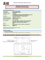
1
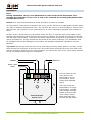
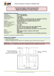
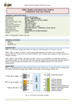
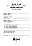
R
Please leave this guide with the end user.
Wireless thermostat SI-2
Installation and user guide
Technical specifications
Manufacturer:
Sikom AS, Norway
Type/Model:
SI-2/ 300-8061V12
Compatible with:
A-Comfort
Operating voltage:
230VAC
Max load:
16A resistive. Above 10A an auxiliary contactor
is recommended against heat build-up.
Regulation:
ON/OFF with about 1°C hysteresis.
Room/Floor sensor:
10K NTC at 25°C
Measurement range:
-28°C to +49°C ±2°C
Temp. compensation:
0°C to +9°C
Operating temp.:
0°C to +40°C
Dim (LxHxD):
84 x 84 x 45 mm (overall, incl. cover frame)
50 x 50 x 45 mm (effective, DIN 49075)
Minimal recess: 50 x 50 x 30 mm
Weight:
95 g
Color:
White (polar white, similar to RAL 9010)
Radio Frequency:
433.9 MHz
Sealing:
IP20
Complies with the European R&TTE directive.
Designed for indoor use only.
Package contents
• Wireless thermostat
• Front cover and frame.
•
Temperature sensor with 3m cable. Called “sensor” in the following.
NB: This thermostat does not offer galvanic separation between high and low voltages.
The sensor must therefore be regarded as a high voltage cable.
Temperature sensor:
NTC, watertight,
shielding with earthing contact.
Load: 230V/50Hz
max 16A
Electronics
64-311-11-Manual-Thermostat-SI-2-Rev2.0-ENG-CH.doc
R
Please leave this guide with the end user.
Installation
Note:
During installation, the top cover MUST NOT be removed from the thermostat. This
protects the electronics. Front cover is only to be removed for mounting the plastic frame
(combination cover).
Sensor: The wire from thermostat to sensor should be as short as possible.
As room sensor: If the sensor is placed in the room, pull the sensor to an appropriate location where
you want to measure temperatures from. Do not place the sensor in direct sunlight or close to other
heat sources. Do not place it on an external wall or in zones exposed to draughts from windows or
doors.
As floor sensor: If the sensor is to be placed under the floor, it must be right in the middle of two
heating cable segments, and as close to the surface as possible. The sensor wire should not be laid
out near high current cables. The sensor should be placed inside a pipe that is grounded or covered
with a grounded net. The pipe should also be closed at the sensor extremity. The installation shall
be equipped with an earth leakage circuit breaker. All standard installation regulations must be
followed.
Top cover: On the top of the box there are 4 protruding mounting claws (about 1 cm high). These
claws fit into the cooling fins of the top cover. Be careful when mounting the front cover and verify
that the mounting claws are in the correct position. To remove the front cover, press gently inwards
on the mounting claws through the cooling fins.
230VAC
N
230V load
L
Room / Floor
sensor
R G
L
N
N
O
Thermostat SI-2
Bottom view
64-311-11-Manual-Thermostat-SI-2-Rev2.0-ENG-CH.doc
The flip switch on the
front panel of the
thermostat is a twopole breaker, which
breaks both leads N
and L.
The relay inside the
thermostat is a singlepole breaker. Lead N
goes straight through.
Lead L connects to O
when relay is active.
Both leads pass first
through the flip switch.
R
Please leave this guide with the end user.
Registration with central unit
•
•
•
•
Choose Main menu 8 “Node” on the central unit (SI-2 is viewed as a “Node”).
Please refer to the node registration procedure in the user manual of the central unit.
Select sub-menu “New node” and press OK.
Turn on the thermostat using the on/off flip switch.
”New noden OK” and a number will now be shown in the display of the central unit. Take note of
this number for the end user; this number will be used for remote control of the thermostat.
SIKOM AS
20
SI-2
Display, LEDs and flip switch
• Element on/off:
Lights when the heating element receives current
(i.e. when thermostat relay is active)
• Comfort:
Comfort mode active.
• Eco:
Eco mode active.
• On/Off switch:
Position 0 turns off all power, including the thermostat itself.
The display shows the currently measured temperature. If the sensor is under the floor, it measures
in fact the temperature inside the floor. Negative temperatures are shown with two dots being lit at
the bottom of the display.
Possible
• E0:
• E1:
• E2:
errors
Temperature sensor is not connected or faulty.
Faulty radio (thermostat cannot communicate with the central unit).
Overheating inside the thermostat. Check the load.
Errors will be shown in the display if there is something wrong with the functionality.
If the thermostat is overheated, it will turn off the output relay until the temperature inside the unit
is normal again.
If there is something wrong with the sensor, the thermostat will shut down. An error will be shown
in the display.
64-311-11-Manual-Thermostat-SI-2-Rev2.0-ENG-CH.doc
R
Please leave this guide with the end user.
Operation
The thermostat can be configured and operated either remotely (e.g. by SMS messaging) or locally
from the central unit, or finally directly via the thermostat buttons. Please refer to the manual of the
central unit for further information.
The thermostat will automatically dim the display after a while. Before the thermostat can be
operated manually you must press the up or down button so the display gets fully lit.
Switching between eco and comfort modes:
Press the up and down buttons simultaneously to switch between eco / comfort mode. ECO or Cft
will be shown in the display when it switches.
ECO stands for eco modus.
Cft stands for comfort modus.
The target temperature will blink 2 times when toggling between eco and comfort modes.
Adjusting the target temperature:
First, follow the above instructions to set the thermostat into the mode (eco or comfort) to be
adjusted.
• Then press the up or down button: the display will show which mode it is set to, and then the
current target temperature.
• Use the up and down buttons to adjust the target temperature.
• When the desired temperature is displayed, press the up and down buttons simultaneously to
store it.
• St will blink in the display to indicate that the temperature is stored.
Adjusting the brightness:
The range is 0-20, where 0 is the weakest brightness.
• Turn off the thermostat. Press the down button and keep it depressed while turning on the
thermostat. Release the down button. dl will be shown in the display.
• Use the up and down buttons to adjust the brightness.
• Press the up and down buttons simultaneously to store the setting.
• St will blink in the display to indicate that the value is stored.
Adjusting temperature compensation:
The thermostat can be compensated if the displayed temperature is too high. The need for
compensation is more frequent when the sensor is located under the floor. The compensation can be
from 0 to 9 degrees. This means that if the sensor measures 30 degrees and the compensation is
set to 9 degrees, then the entire temperature range of the thermostat will be shifted down by 9
degrees; this will be reflected by the display, which will then show 21 degrees instead of 30.
• Turn off the thermostat. Press the up button and keep it depressed while turning on the
thermostat. Let the button go. tC will be shown in the display.
• Use the up and down buttons to adjust the temperature.
• Press the up and down buttons simultaneously to store the setting.
• St will blink in the display to indicate that the value is stored.
Temperature surveillance with SMS alarm:
The thermostat can be set to monitor the temperature and send an alarm SMS whenever one of the
given limits is exceeded. A lower and upper limit can be entered on the central unit or remotely (by
SMS, etc.). Please refer to the manual of the central unit to this end. When a limit is exceeded, the
central unit will send out an SMS alarm and the surveillance will be disabled: Remember to
reactivate the surveillance after the temperature is back to normal again. Note that the temperature
compensation has an impact on this function.
64-311-11-Manual-Thermostat-SI-2-Rev2.0-ENG-CH.doc
R
Please leave this guide with the end user.
How it works
The thermostat gives power to the connected heating element when the measured ambient
temperature is below the desired value, minus 1 degree. That is, if the target temperature is set to
20 degrees, the thermostat switches on the heating element when the ambient temperature falls
below 19 degrees. It switches off again when the ambient temperature reaches 20 degrees. There is
additionally a minimum delay of 15 seconds between each time the system toggles from one state
to another.
Please note that the displayed ambient temperature is the one measured by the sensor. This means
that if the sensor is laid out under the floor, it will measure the temperature of the floor: this
temperature will always be different from the real temperature in the room. Therefore, it is possible
to set a temperature compensation as explained in Section “Operation”, but you must be ready to
still experience some variations, which means that temperature readings may differ from the real
temperature. The “eco” and “comfort” target temperatures may also have to be adjusted
experimentally until the desired ambient temperature is achieved.
Negative temperatures are shown with two dots at the bottom of the display. This applies to actual
temperature readings as well as to “eco” and “comfort” target temperatures.
The thermostat communicates wirelessly with the central unit, but works basically as an
autonomous device. All settings can be adjusted on the front panel of the thermostat. However,
temperature alarms and remote control functions require a central unit with a valid GSM
subscription.
64-311-11-Manual-Thermostat-SI-2-Rev2.0-ENG-CH.doc
R
Please leave this guide with the end user.
COMPLIANCE WITH INTERNATIONAL REGULATIONS
This equipment complies with the European R&TTE directive. Further information may be obtained
by contacting your dealer or the manufacturer:
Sikom AS (www.sikom.no)
Neptunveien 6
7650 Verdal
Norway
WARRANTY
Sikom A.S. products are covered by a two years warranty against any faults due to material flaws or
manufacturing errors, which limit or render useless certain functions described for the product. The
warranty requires the customer to present the original bill, with date of purchase and type of
equipment clearly readable.
What is covered by the warranty?
During the warranty period, Sikom A.S. reserves the right to repair the product or to replace
defective parts with functionally equivalent parts. If, after several attempts, Sikom A.S. is unable to
correct the problem, and the product does not work as described in the manual, Sikom may elect to
refund the purchase price or to replace the product with a functionally equivalent one. All replaced
parts and products become the property of Sikom A.S.
What is not covered by the warranty?
• Indirect damage to life, health, property, revenue and environment caused by circuits and
appliances connected to the units (install and use this product responsibly).
• Costs related to (re)installing, transporting and dismantling units; recycling may be governed by
special rules (see the relevant chapter).
• Damages caused by use outside of the operating conditions specified in the manual.
• Malfunctions caused by transport damages.
• Any unauthorized repair, modification or disassembly.
• Use of non-original parts.
• External factors, such as lightning, power supply issues, mobile network issues, flood damage or
fire.
• Units with modified, removed or unreadable serial number.
Sikom assumes no responsibility for any errors that may appear in this manual.
Information contained herein is subject to change without notice.
RECYCLING INFORMATION
The WEEE (Waste Electrical and Electronic Equipment) symbol indicates that this product must not
be disposed of along with other household waste. It is the customer's responsibility to dispose of the
product properly by taking it to a designated site for recycling. To locate a recycling/disposal site
near you, contact your local city recycling program, your regular waste disposal service or the agent
from whom you purchased this product.
For Switzerland, this product includes in its purchase price a contribution (the advanced recycling
fee) to the SWICO Recycling Warranty, which means that used equipment can be handed in free of
charge for recycling. Collection sites are listed at www.swicorecycling.ch.
64-311-11-Manual-Thermostat-SI-2-Rev2.0-ENG-CH.doc