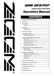
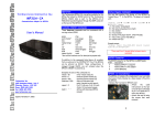
1
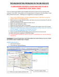
BBI Engineering, Inc.
MicroMSC
MicroMSC User Manual
1
Introduction
The BBI Micro Multifunction Show Controller was designed to handle the needs of local
exhibit control, small media shows, and theme attractions. The unit can act either in standalone
mode or in slave mode for compatibility with AMX and Crestron show control systems. As a
show controller, it operates DVD, LD and CD players, lighting controls and other serial devices
using RS-232, and RS-422. The μMSC responds to closures (button pushes) or open collector
logic on its digital I/O ports, and serial commands on its device ports. When used as outputs,
the digital I/O ports drive tally lights or other low current devices and relays. PWM signals
provide dimming of tally lights or driving of servo positioners. A quadrature encoder may be
used for position monitoring. A potentiometer may be connected to the ADC inputs for external
volume control. The two on-board relays are able to handle high current (2A at 30V max)
devices to make integration into exhibits easier. Power can either be supplied by an external
power supply or through PoE to ease the total number of wires brought to the device.
2
Physical Layouts and Connections
Front Panel Details
Back Panel Details
241 Quint Street, San Francisco CA 94124
Tel: (415) 695-9555 Fax: (415) 695-9276
[email protected]
www.bbinet.com
BBI Engineering, Inc.
3
MicroMSC
Communication Protocol
The MicroMSC can communicate with other host computers with UDP and TCP protocol. It
also supports Telnet protocol at the standard Telnet port 23. It can support up to 8 simultaneous
TCP connections. The number of UDP host is unlimited. However, only the first 8 UDP hosts
will receive subscription updates. The default MicroMSC UDP and TCP port is 10004 (or
Telnet port 23). TCP connections can also be made to ports 10005, 10006 and 10007. These
three TCP connections act as transparent pipes to the three serial ports. Data sent to port 10005
will be forwarded to serial port 1 and data received at serial port 1 will be forwarded to TCP
port 10005. The serial port settings can be changed by sending the “PC” command to the
control port 10004 (or Telnet port 23).
All the control commands consists of 7-bit readable ASCII characters. Most commands consist
of a 2-letter command code followed by optional comma separated command arguments and
carriage return (<CR>, ASCII code 13) and linefeed (<LF>, ASCII code 10):
CM,Arg1,Arg2,...<CR><LF>
The linefeed character is optional. However, the Telnet protocol automatically assumes each
line to be terminated by <CR><LF>. The same command can be used to change or query a
property value. To change the property value, just supply the new value as the last command
argument. To query the property value, simply enter the command without the last command
argument. All replies from the unit begins with '*'. For example if the digital output 1 is
currently off (logic one), The command
DO,1<CR><LF>
will return the current state of the digital output 1:
*DO,1,0<CR><LF>
Similarly, the command
DO,1,1<CR><LF>
will turn on digital output 1 (output would be pulled to logic zero) and the reply from the unit
will be
*DO,1,1<CR><LF>.
When the command failed to execute the reply will be in the following format
*CM,Error: error message<CR><LF>
Some commands do not have a return value, a successfully executed command would reply
*CM,OK<CR><LF>
3.1
AI – analog input
Read the analog level at I/O pin 7 and 8. The only acceptable options are
AI,7<CR><LF>
241 Quint Street, San Francisco CA 94124
Tel: (415) 695-9555 Fax: (415) 695-9276
[email protected]
www.bbinet.com
BBI Engineering, Inc.
MicroMSC
AI,8<CR><LF>
The returned value is between 0 and 1023. For example,
Send: AI,7<CR><LF>
Rcvr: *AI,7,645<CR><LF>
3.2
DA – set or get current Date
DA<CR><LF> returns the current date maintained by the controller. To set the date enter
DA,mon,day,year<CR><LF> where mon is the month between 1 and 12, day is day of the
month between 1 and 31 and year is the current year. If year is less than 100, 2000 will
automatically be added. For example, to get the current date
Send: DA<CR><LF>
Rcvr: *DA,10,07,2008<CR><LF>
Or to set the date
Send: DA,10,07,2008<CR><LF>
Rcvr: *DA,10,07,2008<CR><LF>
3.3
DC – PWM duty cycle
Use the DC command to set or get the PWM duty cycle for a given digital output pin. The
syntax is
DC,dout#<CR><LF>
to get the current PWM duty cycle, in percent, for output pin dout# and
DC,dout#,dc<CR><LF>
to set the PWM duty cycle at output pin dout# to dc percent. dout# must be between 1 and
8 and dc must be between 0 and 100. For example, to get the current duty cycle for digital
output pin 1
Send: DC,1<CR><LF>
Rcvr: *DC,1,50<CR><LF>
Or to set the duty cycle to 45%
Send: DC,1,45<CR><LF>
Rcvr: *DC,1,45<CR><LF>
241 Quint Street, San Francisco CA 94124
Tel: (415) 695-9555 Fax: (415) 695-9276
[email protected]
www.bbinet.com
BBI Engineering, Inc.
3.4
MicroMSC
DI – digital input state
Use the DI command to get the current digital logic state of a given digital input pin. The
syntax is
DI,din#<CR><LF>
din# must be between 1 and 8. For example,
Send: DI,3<CR><LF>
Rcvr: *DI,3,1<CR><LF>
3.5
DL – audio output delay in milliseconds
Use the DL command to get and set the delay for the audio output channels. The syntax is
DL,ch#<CR><LF>
to get the current delay for output channel ch#. ch# must be 1 or 2. The syntax to set the
delay is
DL,ch#,delay_in_ms<CR><LF>
Ch# must be between 1 and 2 and the maximum delay is 18ms. For example, to get the
delay
Send: DL,1<CR><LF>
Rcvr: *DL,1,10<CR><LF>
Or to set the delay
Send: DL,1,5<CR><LF>
Rcvr: *DL,1,5<CR><LF>
3.6
DO – digital output state
Use the DO command to get or set the state of a given digital output line. The syntax is
DO,dout#<CR><LF>
to get the current state of digital output dout#, or
DO,dout#,state<CR><LF>
to set the state of the line. dout# is between 1 and 8 and State is 1 or 0. Output state of 1
241 Quint Street, San Francisco CA 94124
[email protected]
Tel: (415) 695-9555 Fax: (415) 695-9276
www.bbinet.com
BBI Engineering, Inc.
MicroMSC
means that the output transistor conducts and pulls the output to logic zero. For example, to
get the current state
Send: DO,5<CR><LF>
Rcvr: *DO,5,0<CR><LF>
Or to set the state
Send: DO,5,1<CR><LF>
Rcvr: *DO,5,1<CR><LF>
3.7
Exit – terminate the TCP connection
This is one of those commands that are more than 2 characters long. This command has no
effects when sent over as an UDP packet.
3.8
FE – enable/disable an audio filter
The syntax is
FE,ch#,filter#<CR><LF>
to get the current state of filter# for audio output channel ch#, or
FE,ch#,filter#,enable<CR><LF>
to enable or disable the filter. Ch# is 1 or 2, filter# is 1 to 8. The allowable values for
enable are 1 or 0. For example, to get the current state of a filter
Send: FE,1,3<CR><LF>
Rcvr: *FE,1,3,1<CR><LF>
Or to enable a filter
Send: FE,1,3,1<CR><LF>
Rcvr: *FE,1,3,1<CR><LF>
3.9
FF – frequency of audio filter
Use the FF command to set or get the frequency of a given audio filter for a given audio
channel. The syntax is
FF,ch#,filter#<CR><LF>
241 Quint Street, San Francisco CA 94124
Tel: (415) 695-9555 Fax: (415) 695-9276
[email protected]
www.bbinet.com
BBI Engineering, Inc.
MicroMSC
to get the frequency of filter# for audio output channel ch#, or
FF,ch#,filter#,freq<CR><LF>
to set the frequency. ch# is between 1 and 2, filter# is between 1 to 8 and the freq must be
between 10Hz and 20kHz. For example, to get the current frequency of a filter
Send: FF,2,3<CR><LF>
Rcvr: *FF,2,3,1000<CR><LF>
Or to set the frequency
Send: FF,2,3,1000<CR><LF>
Rcvr: *FF,2,3,1000<CR><LF>
3.10 FG – gain of audio filter
Use the FG command to set or get the gain of a given audio filter for a given audio channel.
The syntax is
FG,ch#,filter#<CR><LF>
to get the gain of filter# for audio output channel ch#, or
FG,ch#,filter#,gain<CR><LF>
to set the frequency. ch# is between 1 and 2, filter# is between 1 to 8 and the gain is in
multiples of 0.1dB. The valid range for gain is -400 to 150 for -40dB to 15dB. Not all filter
types support the FG command. For example, to get the current gain of a filter
Send: FG,2,3<CR><LF>
Rcvr: *FG,2,3,-60<CR><LF>
Or to set the gain
Send: FG,2,3,30<CR><LF>
Rcvr: *FG,2,3,30<CR><LF>
3.11 FP – factory preset
The FP command reset the unit to the factory preset state. However it does not change the
network parameters. For example,
Send: FP<CR><LF>
Rcvr: *FP,OK<CR><LF>
241 Quint Street, San Francisco CA 94124
Tel: (415) 695-9555 Fax: (415) 695-9276
[email protected]
www.bbinet.com
BBI Engineering, Inc.
MicroMSC
3.12 FQ – gain of audio filter
Use the FQ command to set or get the Q (Quality factor) of a given audio filter for a given
audio channel. The syntax is
FQ,ch#,filter#<CR><LF>
to get the Q of filter# for audio output channel ch#, or
FQ,ch#,filter#,Q<CR><LF>
to set the Q. ch# is between 1 and 2, filter# is between 1 and 8 and the Q is in multiples of
0.1. The valid range for Q is 1 to 100 for Q between 0.1 to 10. The only exception is when
the filter type is a Phase filter. The Phase filter does not have Q as a parameter. The FQ
command is used to set the phase at the center frequency and Q would be in the range of 180 to 180 degrees.
For example, to get the current Q of a filter
Send: FQ,2,3<CR><LF>
Rcvr: *FQ,2,3,10<CR><LF>
Or to set the gain
Send: FQ,2,3,30<CR><LF>
Rcvr: *FQ,2,3,30<CR><LF>
3.13 FT – audio filter type
Use the FT command to set or get the audio filter type and filter order. The syntax is
FT,ch#,filter#<CR><LF>
to get the filter type and filter order, or
FT,ch#,filter#,type,order<CR><LF>
to set the filter type and order. ch# is the audio channel number between 1 and 2, filter# is
between 1 and 8, order is the filter order and its range is determined by filter type. The
supported filter types are:
0 – standard 2nd order parametric EQ filter
1 – 2nd order low pass filter with variable Q
2 – 2nd order high pass filter with variable Q
3 – 1st order low pass filter with variable Q
4 – 1st order high pass filter with variable Q
241 Quint Street, San Francisco CA 94124
Tel: (415) 695-9555 Fax: (415) 695-9276
[email protected]
www.bbinet.com
BBI Engineering, Inc.
MicroMSC
5 – Butterworth low pass filter with order between 1 and 8
6 – Butterworth high pass filter with order between 1 and 8
7 – Linkwitz Riley low pass filter with order between 1 and 8
8 – Linkwitz Riley high pass filter with order between 1 and 8
9 – Bessel low pass filter with order between 1 and 8
10 – Bessel high pass filter with order between 1 and 8
11 – 2nd order low shelf filter with variable Q
12 – 2nd order high shelf filter with variable Q
13 – 2nd order All pass filter
14 – 2nd order true band pass filter
15 – 1st order phase filter
16 – invalid filter type
For example, to get the current filter type and order
Send: FT,1,2<CR><LF>
Rcvr: *FT,1,2,0,2<CR><LF>
Or to set the filter type
Send: FT,1,2,0,2<CR><LF>
Rcvr: *FT,1,2,0,2<CR><LF>
3.14 GL – global delay in milliseconds
Use the GL command to set or get the global audio delay of the unit. This delay applies to
both audio channels on top of the channel-wise delay. The syntax is
GL<CR><LF>
to get the current global delay or
GL,delay<CR><LF>
to set the delay. delay is in milliseconds between 0 and 18. For example, to set the delay
Send: GL,5<CR><LF>
Rcvr: *GL,5<CR><LF>
3.15 GV – global audio volume
Use the GV command to set or get the global audio output volume. This volume applies to
both audio channels on top of the channel-wise volume. The syntax is
241 Quint Street, San Francisco CA 94124
Tel: (415) 695-9555 Fax: (415) 695-9276
[email protected]
www.bbinet.com
BBI Engineering, Inc.
MicroMSC
GV<CR><LF>
to get the current global volume or
GV,vol<CR><LF>
to set the volume. vol is in multiple of 0.1dB. The range of vol is between -1000 to 240,
corresponds to -100dB to 24dB. For example, to set the global volume
Send: GV,-60<CR><LF>
Rcvr: *GV,-60<CR><LF>
3.16 GM – global audio mute
Use the GM command to set or get the global audio mute state. This mute applies to both
channels and does not affect the channel-wise mute state. The syntax is
GM<CR><<LF>
to get the current mute state or
GM,mute<CR><LF>
to set the global mute state. mute is 1 or 0. For example, the mute both outputs
Send: GM,1<CR><LF>
Rcvr: *GM,1<CR><LF>
3.17 GW – network gateway address
Use the GW command to get or set the Ethernet gateway address. The syntax is
GW<CR><LF>
to get the current gateway address held by the unit, or
GW,gw1,gw2,gw3,gw4<CR><LF>
to set the gateway address. gw1, gw2, gw3 and gw4 are between 0 and 255.
gw1.gw2.gw3.gw4 forms the IP address of the network gateway. For example, to set the
gateway address
Send: GW,192,168,1,254<CR><LF>
Rcvr: *GW,192,168,1,254<CR><LF>
The change will not take effect until the unit is rebooted.
241 Quint Street, San Francisco CA 94124
Tel: (415) 695-9555 Fax: (415) 695-9276
[email protected]
www.bbinet.com
BBI Engineering, Inc.
MicroMSC
3.18 IM – input mode for digital input 7 and 8
Input 7 and 8 can be set to analog or digital mode. Each digital input pin has an internal
pullup resistor of 1.8K ohms. When the external voltage source has a source impedance not
large compared to 1.8K ohms (for example 10K ohms), the internal pull resistor would
affect the voltage measured by the internal ADC circuits. Setting the pin to analog mode
would disable the internal pull resistor so that the sampled value would reflect the correct
voltage level at the pin. The syntax is
IM,din#<CR><LF>
to get the current pin mode, or
IM,din#,mode<CR><LF>
to set the mode. din# must be 7 or 8. mode must be the character a, A, d or D, a and A for
analog mode and d or D for digital mode. For example
Send: IM,7,a<CR><LF>
Rcvr: *IM,7,a<CR><LF>
would set input 7 to analog mode.
3.19 IO – simultaneous input/output mode
Each digital pin can be use as input, output or input/output simultaneously. When a pin is
set to simultaneous input/output mode, the output is disabled briefly periodically so that the
input state can be sampled. Otherwise, setting the output to low would force the input state
of that pin to low and setting the output to high would force the input state to high. The
syntax is
IO,io#,<CR><LF>
to get the current mode, or
IO,io#,1<CR><LF>
to turn on simultaneous input/output mode or
IO,io#,0<CR><LF>
to turn off simultaneous mode. io# is the I/O pin number between 1 and 8. For example,
Send: IO,5,1<CR><LF>
Rcvr: *IO,5,1<CR><LF>
241 Quint Street, San Francisco CA 94124
Tel: (415) 695-9555 Fax: (415) 695-9276
[email protected]
www.bbinet.com
BBI Engineering, Inc.
MicroMSC
would turn on simultaneous input/output mode for I/O pin 5.
3.20 IP – network IP address
Use the IP command to get or set the Ethernet IP address of the unit. The syntax is
IP<CR><LF>
to get the current IP address of the unit, or
IP,ip1,ip2,ip3,ip4<CR><LF>
to set the IP address. ip1, ip2, ip3 and ip4 are between 0 and 255. ip1.ip2.ip3.ip4 forms the
IP address of the unit. For example, to set the IP address
Send: IP,192,168,1,1<CR><LF>
Rcvr: *IP,192,168,1,1<CR><LF>
The change will not take effect unit the unit is rebooted.
3.21 IR – fire an IR pulse
Use the IR command to fire an IR pulse to a give digital output pin. The syntax is
IR,dout#,sink,filename,codename
or
IR,dout#,sink,filename,codename,repeat
where dout# is the digital output number between 1 and 8. sink should be set to 1 when the
IR LED is connect to the output and pulled up to 12V with a resistor. sink should be 0 when
the IR LED is connected to the output and ground. filename is the name of the IR file
transferred to the /IR folder of the internal flash filesystem via FTP. filename must be in 8.3
format and should not contain folder information (no /IR prepended). codename is the
name of the code to be fired. codename is defined inside the IR file. The optional parameter
repeat defines how many times the repeat section of the code will be repeated. When repeat
is missing, the repeat section of the code will be fired 3 times. (Each code consists of an
optional header section that will be fired once and a repeat section that can be repeated).
For example,
Send: IR,3,1,aquos.irl,power_on<CR><LF>
Rcvr: *IR,OK<CR><LF>
241 Quint Street, San Francisco CA 94124
Tel: (415) 695-9555 Fax: (415) 695-9276
[email protected]
www.bbinet.com
BBI Engineering, Inc.
MicroMSC
will fire the power_on code from the file aquous.irl three times to output pin 3.
3.22 MU – audio mute
Use the MU command to mute/unmute a given audio channel. The syntax is
MU,ch#<CR><LF>
to obtain the current mute state, or
MU,ch#,mute<CR><LF>
to set the mute state of the channel. Ch# is the audio channel number between 1 and 2.
mute is 1 to mute the output or 0 to unmute the output. For example,
Send: MU,1,1<CR><LF>
Rcvr: *MU,1,1<CR><LF>
will mute output channel 1.
3.23 MX – set mixer cross point value
There is a 2x3 matrix mixer at the input of the on board digital signal processor. This will
allow mixing of audio input 1, audio input 2 and the internal signal generators to form the
input of the two audio channels. The syntax is
MX,out#,src#<CR><LF>
to get the current cross point value, or
MX,out#,src#,val<CR><LF>
to set the cross point value. out# is the output channel number between 1 and 2. src# is the
input source between 1 and 4, 1 for analog input 1, 2 for analog input 2, 3 for internal white
noise generator and 4 for internal pink noise generator. val is the cross point value in
multiples of 0.1dB, and it must be non-positive. For example,
Send: MX,1,2,-60<CR><LF>
Rcvr: *MX,1,2,-60<CR><LF>
would send half (-6dB) of analog input 2 to output channel 1.
241 Quint Street, San Francisco CA 94124
Tel: (415) 695-9555 Fax: (415) 695-9276
[email protected]
www.bbinet.com
BBI Engineering, Inc.
MicroMSC
3.24 NM – network subnet mask
Use the NM command to get or set the Ethernet network subnet mask. The syntax is
NM<CR><LF>
to get the current subnet mask held by the unit, or
NM,nm1,nm2,nm3,nm4<CR><LF>
to set the subnet mask. nm1, nm2, nm3 and nm4 are between 0 and 255. nm1.nm2.nm3.nm4
forms the subnet mask of the network. For example, to set the subnet mask
Send: NM,255,255,255,0<CR><LF>
Rcvr: *NM,255,255,255,0<CR><LF>
The change will not take effect until the unit is rebooted.
3.25 PC – serial port configuration
Use the PC command to get or set the configuration parameter of a given serial port. The
syntax is
PC,port#<CR><LF>
to get the current configuration, or
PC,port#,baud,datasize,parity,stopbit<CR><LF>
to set the configuration. port# is the serial port number between 1 and 3. baud is the
baudrate, datasize is the character size between 5 and 8. parity is the parity and the
supported options are
n or N – none
o or O – odd
e or E – even
m or M – mark
s or S – space
stopbit is the number of stop bit between 1 and 2. For example,
Send: PC,1,9600,8,N,1<CR><LF>
Rcvr: *PC,1,9600,8,N,1<CR><LF>
would set the port to 9600 baud, 8-bit characters, no parity and 1 stop bit.
241 Quint Street, San Francisco CA 94124
Tel: (415) 695-9555 Fax: (415) 695-9276
[email protected]
www.bbinet.com
BBI Engineering, Inc.
MicroMSC
3.26 PE – PWM enable/disable
Use the PE command to turn on or off PWM mode for a given digital output pin. The
syntax is
PE,dout#<CR><LF>
to get the current PWM mode, or
PE,dout#,mode<CR><LF>
to set the PWM mode. dout# is the digital output number between 1 and 8. mode is 1 to
turn on PWM mode, or 0 to turn off PWM mode. For example,
Send: PE,2,1<CR><LF>
Rcvr: *PE,2,1<CR><LF>
would turn on PWM mode at output pin 2.
3.27 PF – PWM frequency
Use the PF command to get or set the digital output PWM frequency. This frequency is
applied to all output pins with PWM mode turned on. The syntax is
PF<CR><LF>
to get the current PWM frequency, or
PF,freq<CR><LF>
to set the PWM frequency. freq is the PWM frequency in Hertz. The factory default
frequency is 1kHz. For example,
Send: PF,500<CR><LF>
Rcvr: *PF,500<CR><LF>
would set the PWM frequency to 500 Hz.
3.28 PN – ping
Ping the unit to keep its subscription. See the SU command for details
3.29 PR – recall preset
Use the PR command to recall a preset. Preset files are stored in XML format in the /preset
241 Quint Street, San Francisco CA 94124
[email protected]
Tel: (415) 695-9555 Fax: (415) 695-9276
www.bbinet.com
BBI Engineering, Inc.
MicroMSC
folder of the internal flash filesystem. The syntax is
PR,filename<CR><LF>
where filename is the filename of the preset (without /preset) and must be in 8.3 format.
For example,
Send: PR,preset1.xml<CR><LF>
Rcvr: *PR,OK<CR><LF>
would recall preset from the file /preset/preset1.xml.
3.30 PS – save a preset
Use the PS command to save the current state of the unit to a preset file. Preset files are
stored in XML format in the /preset folder of the internal flash filesystem. The syntax is
PS,filename<CR><LF>
where filename is the filename of the preset (without /preset) and must be in 8.3 format.
For example,
Send: PS,preset1.xml<CR><LF>
Rcvr: *PS,OK<CR><LF>
would save the current state to the file /preset/preset1.xml.
3.31 QUIT – terminate the TCP connection
This command is identical to the EXIT command.
3.32 RE – reboot
RE<CR><LF> would cause a reboot of the unit.
3.33 RFC – RFC2217 mode
The three serial ports are mapped to three TCP connections. The TCP connections can
support RFC2217 protocols which allows port configuration by sending 0xFF escaped
binary sequences. When RFC2217 mode is on, normal 0xFF should be sent as two
consecutive 0xFF. The RFC command can be used to turn on/off the RFC2217 protocol.
The syntax is
RFC,port#<CR><LF>
241 Quint Street, San Francisco CA 94124
Tel: (415) 695-9555 Fax: (415) 695-9276
[email protected]
www.bbinet.com
BBI Engineering, Inc.
MicroMSC
to check the current setting and
RFC,port#,enable<CR><LF>
to enable/disable the RFC2217 protocol. port# is the serial port number between 1 and 3.
enable is 1 or 0. For example,
Send: RFC,1,1<CR><LF>
Rcvr: *RFC,1,1<CR><LF>
to enable RFC2217 protocol for serial port 1.
3.34 RL – relay state
The RL command can be used to get or set the state of the relays. The syntax is
RL,rly#<CR><LF>
to get the state of a relay, or
RL,rly#,state<CR><LF>
to set the state of a relay. rly# is the relay number between 1 and 2. Set state to 1 to energy
the relay coil, i.e., engage the relay, or set state to 0 to release the relay. For example,
Send: RL,1,1<CR><LF>
Rcvr: *RL,1,1<CR><LF>
will engage relay 1.
3.35 RT – input sample duration count for digital input in simultaneous input/output mode
When a digital input is in simultaneous input/output mode, the output is periodically turned
off momentarily to sample the input state of the pin. The sample duration can be modified
with the RT command. The default RT value is 5, corresponds to a sample duration of about
100us (not really, need to turn on the unit to measure this). This value works well when the
output current is low and the load is not too capacitive or inductive. When the output
current is high or the output is driving a long cable, the capacitance/inductance of the cable
would prevent the output to be released to high state for the input state to be sampled. In
that case, the RT value must be increased. The syntax of the RT command is
RT<CR><LF>
241 Quint Street, San Francisco CA 94124
Tel: (415) 695-9555 Fax: (415) 695-9276
[email protected]
www.bbinet.com
BBI Engineering, Inc.
MicroMSC
to get the current value and
RT,cnt<CR><LF>
to set the value to cnt. For example,
Send: RT,6<CR><LF>
Rcvr: *RT,6<CR><LF>
would set the duration count to 6.
3.36 SC – scan for units on the network
SC is usually issued as a UDP broadcast packet. Any MicroMSC units online will response
to such broadcast packet and a reply will be broadcast back to the sender's UDP port. This
allows the sender to scan for online units across IP subnets. The typical response of the SC
command is
SC,MicroMSC,serial#,firmwareVersion,hardwareRevision<CR><LF>
where serial# is the serial number of the unit. FirmwareVersion is the firmware version and
hardwareRevision is the hardware revision. The SC command can also be sent over the
TCP connection to obtain the same information. For example,
Send: SC<CR><LF>
Rcvr: *SC,MicroMSC,00001,V1.0,Rev.A<CR><LF>
3.37 SP – send string to a serial port
Use the SP command to send a string to a serial port. The is typically sent as a UDP packet
to port 10004. It allows the remote end to send a string to the serial port without making a
TCP connection to ports 10005, 10006 or 10007 that mapped to the serial ports. Since the
string can have any hexadeciaml value, we need to include the string length in the
command. The syntax is
SP,port#,length,string<CR><LF>
where port# is the serial port number between 1 and 3. length is the length of the string to
be sent and string is the string to be sent. For example,
Send: SP,1,5,Hello<CR><LF>
Rcvr: *SP,OK<CR><LF>
241 Quint Street, San Francisco CA 94124
Tel: (415) 695-9555 Fax: (415) 695-9276
[email protected]
www.bbinet.com
BBI Engineering, Inc.
MicroMSC
3.38 SU – subscribe
When a remote host is communicating with a MicroMSC, it may receive unsolicited
packets from the MicroMSC. For example, when a button connected to a digital input is
pushed, a DI command response would be sent to all hosts that have an active connection to
the MicroMSC. Similarly, when a host sends a command to change the state of a
MicroMSC parameter, all the other hosts that have an active connection to that MicroMSC
unit will get the same command response. This will guarantee that all hosts to be
synchronized. There are two different kind of unsolicited packets. One kind is related to all
essential parameters of the MicroMSC. The other kind is related to optional status, like the
peak audio input and output levels and quadrature encoder positions. The first kind of
unsolicited packets will always be sent whenever the parameter states are changed. The
second kind will not be sent unless a host has subscribed to the MicroMSC with the SU
command. The syntax of the SU command is
SU<CR><LF>
to check the current subscription state and
SU,subscribe<CR><LF>
to change the subscription state, where subscribe is 1 or 0. For example,
Send: SU,1<CR><LF>
Rcvr: *SU,1<CR><LF>
would turn on subscription. Once a subscription is turned on, the host must keep it turned
on by sending in other commands or sending the PN (ping) command. If no command is
received in 3 minutes the subscription will be terminated. A TCP host's subscription will
automatically be terminated when the TCP connection is closed.
3.39 TI – get or set time
Use the TI command to get or set the time maintained by the realtime clock. The syntax is
TI<CR><LF>
to get the current time or
TI,hour,minute,second<CR><LF>
to set the time. hour is the current hour between 0 and 23. minute is the current minute
between 0 and 59 and second is the current second between 0 and 59. For example,
Send: TI,10,23,45<CR><LF>
241 Quint Street, San Francisco CA 94124
Tel: (415) 695-9555 Fax: (415) 695-9276
[email protected]
www.bbinet.com
BBI Engineering, Inc.
MicroMSC
Rcvr: *TI,10,23,45<CR><LF>
would set the unit's time to 10:23:45.
3.40 TV – tie an analog input to a volume
When I/O pin 7 or 8 is set to analog mode, their analog value can be tied to a volume
control. So when the analog value is changed, the unit automatically changes the
corresponding volume. The TV command allow specifies which volume to be tied to an
analog input. The syntax is
TV,io#<CR><LF>
to get the current volume tie, or
TV,io#,volCtrl<CR><LF>
to set a volume tie. io# is the analog input and must be 7 or 8. volCtrl can be
0 – no tie
1 – audio channel 1 output volume
2 – audio channel 2 output volume
3 – audio channel 1 and 2 output volumes
4 – global audio volume
For example,
Send: TV,7,4<CR><LF>
Rcvr: *TV,7,4<CR><LF>
will tie analog input 7 to the global audio volume.
3.41 TM – minimum volume allowed when an analog input is tied to a volume control
When an analog input is tied to a volume control with the TV command, the volume
achieved when the analog input value is 0 can be set with the TM command. So when the
TM value is set to -30dB, then the analog input would provide a volume range of -30dB to
0dB. The syntax is
TM,io#<CR><LF>
to get the current minimum volume, or
TM,io#,minVol<CR><LF>
241 Quint Street, San Francisco CA 94124
Tel: (415) 695-9555 Fax: (415) 695-9276
[email protected]
www.bbinet.com
BBI Engineering, Inc.
MicroMSC
to set the minimum volume. io# is the analog input number and must be 7 or 8. minVol is
the minimum volume in dB. minVol must be negative. The default value is -30dB. For
example,
Send: TM,8,-30<CR><LF>
Rcvr: *TM,8,-30<CR><LF>
3.42 VL – audio output volume
The VL command can be used to get or set the output volume of an audio channel. The
syntax is
VL,ch#<CR><LF>
to get the current output volume, or
VL,ch#,vol<CR><LF>
to set the output volume. ch# is the audio channel number between 1 and 2. vol is the
output volume in multiple of 0.1dB. The range of vol is -1000 to 240, corresponding to a
volume of -100dB to 24dB. For example,
Send: VL,1,-60<CR><LF>
Rcvr: *VL,1,-60<CR><LF>
would set audio channel 1 volume to -6dB.
4
Specifications
•
2 audio inputs and outputs
o Volume control between -100 to 0 dB
o Delay, up to 40ms at 48kHz sampling rate
o 8 equalization filters per channel
o Input level jumper allows selection of +12dBu or 0dBu input levels
o Max Output of 12dBu
•
Controls up to 3 serial devices: RS-232 (2 Max), RS-422 (1 Max)
•
3-port 10/100baseT switch with auto negotiation and auto crossover detection
•
Unit maybe be powered with Power Over Ethernet (PoE) or an external power supply at 12V to
24V DC
241 Quint Street, San Francisco CA 94124
Tel: (415) 695-9555 Fax: (415) 695-9276
[email protected]
www.bbinet.com
BBI Engineering, Inc.
MicroMSC
•
Real time clock (RTC) for event scheduling
•
8 digital I/O, with closure detection, PWM output, and 100mA sink at 12V
•
2 of the digital I/O pins may be used as a quadrature decoder
•
2 ADC inputs for voltage based control
•
Infrared Output device control
•
2 Relays, SPDT w/ NC and NO terminals
•
Pluggable barrier strip connectors for easy field wiring
•
Front Panel LEDs indicate power on, digital I/O status and audio signal presence and clip
•
UDP/TCP/Telnet control protocols
241 Quint Street, San Francisco CA 94124
Tel: (415) 695-9555 Fax: (415) 695-9276
[email protected]
www.bbinet.com