1
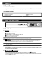
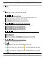
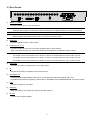
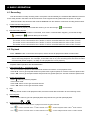
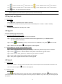
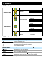
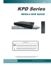
234Z
KPD616
MPEG-4 DVR QUICK
ROHS AND WEEE
All lead-free products offered by the company comply with the requirements of the European law on
the Restriction of Hazardous Substances (RoHS) directive, which means our manufacture processes
and products are strictly “lead-free” and without the hazardous substances cited in the directive.
The crossed-out wheeled bin mark symbolizes that within the European Union the product must be
collected separately at the product end-of-life. This applies to your product and any peripherals
marked with this symbol. Do not dispose of these products as unsorted municipal waste.
Please read this instruction thoroughly before operation and retain it for future reference.
The image shown above may differ from the actual product appearance.
KPD616 Quick _V0.81
1. OVERVIEW
1.1 Product Description
This MPEG-4 multiplex network DVR series combined remote surveillance, burglar prevention, and evidentiary
recording features and is designed to become a simple entry-level system with all necessary functions.
1.2 Package Contents
□ Digital Video Recorder (DVR)
□ Adapter and power cord
□ Manual & quick start
□ Free licensed software AP disc
□ DSUB PIN connector
□ Screws * 4
2. FRONT AND REAR PANELS
PLAY
LIST
LATEST
STOP
1
2
3
4
5
6
7
8
9
SLOW
0
A
B
LIVE
2.1 Front Panel
1)
LED Indication
The following LEDs will be on when:
: When power is connected
: HDD is reading or recording / HDD Full: HDD is full
: Once the alarm or motion is triggered
: When timer recording is activated
Note: If you want to turn off your DVR, please disconnect the power supply.
2)
(USB port)
To quickly backup or upgrade firmware/OSD, you can insert a compatible USB flash drive into this USB port.
Before using the USB flash drive, please use your PC to format the USB flash drive first.
Note: For the list of compatible USB flash drives, please refer to “APPENDIX 2 PIN CONFIGURATION” in
the user manual.
3)
IR receiving zone
If you removed the control panel from the DVR to use as a remote controller, use the remote controller to aim at
this area to control the DVR operation.
4)
(Lock mode) /
(Unlock mode)
To lock the control panel on the DVR, please switch the lock button to the left “
” (lock mode).
If you want to remove the control panel from the DVR to use as a remote controller, please switch the lock button
to the right “
” (unlock mode).
-1-
Note: Due to panel position difference, please place the vertical panel sticker on the removed controller
for operation convenience.
5)
(Menu)
Press this button to enter / exit the quick start menu.
Under the sub-layer of the advanced setting menu,
use this button to confirm the settings and go back to the upper layer.
6)
LIVE
Press this button to stop the playback and return to the live mode.
7)
/
/
/
(Quad display selection)
Under the live or playback mode, press one of these four buttons to select the quad display mode.
: Display Quad 1 mode (4-cut view of CH1, CH2, CH5 and CH6).
: Display Quad 2 mode (4-cut view of CH3, CH4, CH7 and CH8).
: Display Quad 3 mode (4-cut view of CH9, CH10, CH13 and CH14).
: Display Quad 4 mode (4-cut view of CH11, CH12, CH15 and CH16).
8)
/
/
/
(Single channel selection under quad selection mode)
In the quad display mode, press one of these four buttons to select the channel display.
: Display the upper left channel of the selected quad mode.
: Display the upper right channel of the selected quad mode.
: Display the lower left channel of the selected quad mode.
: Display the lower right channel of the selected quad mode.
9)
/
/
/
(16-cut channel display / 9-cut channel display / Quad Sequence / Full Sequence)
Press one of these four buttons to switch the channel display or to activate the sequence mode.
: Display 16-cut display.
: Display 9-cut display.
: Press this button to activate the Quad Sequence mode and press the button again to exit.
: Press this button to activate the Full Sequence mode and press the button again to exit.
10)
1
2
3
4
5
6
/
/
7
8
9
/
0
A
B
(Number buttons for password entering)
Use these four buttons to enter the DVR password.
11)
/
Use these two buttons to select the live or playback sound of the audio channels.
Icon “
” means: Live audio of the 1st audio channel / Icon “
” means: Playback audio of the 1st audio channel
Icon “
” means: Live audio of the 2nd audio channel / Icon “
” means: Playback audio of the 2nd audio channel
Icon “
” means: Live audio of the 3rd audio channel / Icon “
” means: Playback audio of the 3rd audio channel
Icon “
” means: Live audio of the 4th audio channel / Icon “
” means: Playback audio of the 4th audio channel
Icon “
” means: The audio channel is not selected.
Note: If you want to make a video backup with audio, please connect audio cameras to the channels
which support the audio function (CH13, CH14, CH15 and CH16).
-2-
12)
(Key lock)
Press this button to lock keys on the DVR front panel.
(Digital zoom)
13)
Press this button to enlarge the image of the selected channel.
14) ▲ / ▼ / ◄ / ►
Press one of these direction buttons to move the cursor up/down/left/right.
Under DVR menu mode, these direction buttons can use for the following operation:
▲ ▼: Make the selection / Change the settings
◄ ►: Go to the upper layer or sub-layer / Make the selection
15)
Confirm the password entering.
Under the advanced menu, use this button to confirm the settings and go back to the upper layer.
16) LIST
To quick search the recorded files by event list, press this button to show all types of the event lists.
ALARM: List the information of the alarm-trigger-recorded files.
MANUAL: List the information of the manual-recorded files. The DVR will save one recorded file once any recording setting is changed
MOTION: List the information of the motion-trigger-recorded files.
SYSTEM: List the information of the system-recorded files. The DVR system will save one recorded file every one hour.
TIMER: List the information of the timer-recorded files.
17) LATEST
Press this button to playback the latest recorded video.
18) STOP
Press this button to stop playback and return to the live mode.
19) SLOW
Under the playback mode, press this button to slowly playback the recorded file (by 1/4 speed or 1/8 speed).
20) ◄◄ /
/►►
Under the playback mode, press these buttons to fast rewind / pause / fast forward the playback file.
2.2 Remote Controller
If you want to remove the control panel from the DVR to use as a remote controller, please switch the lock button
to the right “
” (unlock mode). Due to the different panel layout, please place the vertical panel sticker on the
controller for operation convenience.
For the detailed instruction, please refer to the remote controller Manual.
-3-
2.3 Rear Panels
1
2
3
4
RS485
IR
5
6
7
EXTERNAL I/O
8
9
11
10
12
13
14
15
16
MONITOR
2
3
4
1
LAN
RI SK OF E LEC TR IC S HO CK
DO NOT OPEN
LINK
ACT.
DC 19V
1)
1
WARNI NG : TO REDUCE THE RISK O F ELECTRIC SHOCK,
DO NOT REMOVE COVER (OR BACK).
NO USER-SERVICEABLE PARTS INSIDE.
REFER SERVICING TO QUALIFIED
SERVICE PERSONNEL.
INPUT (1 ~ 16CH)
Connect to video sources, such as cameras.
Note: The DVR will automatically detect the video system of the camera, please make sure that the
cameras are properly connected to the DVR and power-supplied before the DVR is turned on.
Note: If you want to make a video backup with audio, please connect audio cameras to the channels
which support the audio function (CH13, CH14, CH15 and CH16).
2)
MONITOR
Connect to MAIN monitor for video output.
3)
Audio IN (1 / 2 / 3 / 4)
Connect to audio sources, such as cameras equipped with the audio function.
When users start recording, the audio input will also be recorded with corresponding video channel.
Note: The audio source connected to the “Audio 1” will be recorded with the video of the “CH13”.
The audio source connected to the “Audio 2” will be recorded with the video of the “CH14”.
The audio source connected to the “Audio 3” will be recorded with the video of the “CH15”.
The audio source connected to the “Audio 4” will be recorded with the video of the “CH16”.
4)
Audio OUT
Connect to a monitor or speaker with 1 mono audio output.
5)
IR
Connect the IR receiver extension line for remote control.
6)
EXTERNAL I/O
Insert the supplied 15PIN DSUB to this port for connecting external devices (external alarm, etc).
For detailed I/O port PIN configuration, please refer to “APPENDIX 2 PIN CONFIGURATION” in the user manual.
7)
LAN
Connect to Internet by LAN cable.
8)
LINK ACT.
When your DVR is connected to the Internet, this LED will be on.
9)
DC 19V
Connect to the supplied adaptor.
-4-
3. CONNECTIONS AND SETUP
3.1 Install HDD
Step 1:
Loose the screws on the upper cover and open the upper cover of the DVR.
Step 2:
Screw out the L-shape HDD brackets. Two brackets are used to secure a HDD, and there are 4 of them.
Step 3:
Get a suitable brand HDD and set the HDD mode (Master or Slave).
Note: HDD mode setting rule:
Master if you want to install the HDD to the place near the back panel;
Slave if you want to install the HDD to the place near the front panel.
Step 4:
Attach the bracket to one side of the HDD, and align the screw holes of the bracket with the HDD’s screw holes.
Screw the HDD onto the HDD bracket, two screws for each side. Then, do the same thing to the other side of
the HDD.
Step 5:
Screw the two HDD brackets back to the DVR base.
Step 6:
Connect the HDD to the power connector and IDE BUS (make sure to align the HDD precisely for pin
connection).
For IDE BUS connection:
Connect to the blue IDE BUS connector If the HDD mode is set to Master;
Connection to the gray IDE BUS connector if the HDD mode is set to Slave.
Step 7:
Close the upper cover of the DVR, and fasten all the screws you loosened in Step 1.
3.2 Camera Connection
The cameras must be connected and power-supplied before the DVR is turned on. Connect the camera with the
indicated power supply. And then connect the camera video output to the DVR video input port with a coaxial cable or
RCA lines with BNC connectors (The DVR will automatically detect the video system of the camera).
Note: For detailed DVR video input / output ports, please refer to section “2.3 Rear Panels” at page 4.
For detailed camera operation, please refer to its own manual.
Note: If you want to make a video backup with audio, please connect audio cameras to the channels
which support the audio function (CH13, CH14, CH15 and CH16).
3.3 DVR Power Setup
This device should be operated only with the type of power source indicated on the manufacturer’s label. Connect
the indicated AC power cord to the power adaptor, and plug into an electrical outlet. Power LED “
blue. It takes approximately 10 to 15 seconds to boot the system.
-1-
” will be on as
4. BASIC OPERATION
4.1 Recording
This device offers non-stop recording mode. If the power is off accidentally, the recorded video data will not be lost
and is safely stored in the HDD. The device will return to the original recording status after the power is on again.
When the HDD is full, this device will overwrite 8GB data from the oldest for continuous recording without notice.
1)
Continuous Recording Symbol
When the DVR is properly connected with camera, you can see the sign “
2)
” on the screen.
Event Recording Symbol
When the motion / alarm detection is activated, once motion or external alarm happens, you will see the sign
” (motion) or “
“
” (external alarm) on the screen.
Note: The audio source connected to the “Audio 1” will be recorded with the video of the “CH13”.
The audio source connected to the “Audio 2” will be recorded with the video of the “CH14”.
The audio source connected to the “Audio 3” will be recorded with the video of the “CH15”.
The audio source connected to the “Audio 4” will be recorded with the video of the “CH16”.
4.2 Playback
Press “LATEST” button on the DVR control panel, and the device will playback the latest recorded video.
Note: There must be at least 8192 images of recorded data for playback to work properly. If not, the
device will stop playback. For example, if the IPS is set to 30, the recording time should be at least
273 seconds (8192 images / 30 IPS) for the playback to work properly.
Playback related operations are described below:
1)
Fast Forward (►►) /
Fast Rewind (◄◄)
You can increase the speed for fast forward and rewind on this device. In the playback mode:
Press “►►“ once to get 4X speed forward and press twice to get 8X speed, etc. And the maximum speed is 32X.
Press “◄◄“ once to get 4X speed rewind and press twice to get 8X speed, etc. And the maximum speed is 32X.
2)
Pause ( ) / Image Jog
Press “ ” button to pause the playback.
In the Pause mode:
Press “►►” button once to get one frame forward.
Press “◄◄” button once to get one frame rewind.
3)
Stop
Pressing “STOP” button under playback mode, the screen of this device will return to live monitoring mode.
4)
Slow Playback
Press “SLOW” button to get 1/4X speed playback and press twice to get 1/8X speed playback.
5)
Audio Playback (
/
)
Use these two buttons to select the live or playback sound of the audio channels.
Icon “
” means: Live audio of the 1st audio channel / Icon “
” means: Playback audio of the 1st audio channel
Icon “
” means: Live audio of the 2nd audio channel / Icon “
” means: Playback audio of the 2nd audio channel
-2-
Icon “
” means: Live audio of the 3rd audio channel / Icon “
” means: Playback audio of the 3rd audio channel
Icon “
” means: Live audio of the 4th audio channel / Icon “
” means: Playback audio of the 4th audio channel
Icon “
” means: The audio channel are not selected.
Note: If you want to make a video backup with audio, please connect audio cameras to the channels
which support the audio function (CH13, CH14, CH15 and CH16)
4.3 Key Lock and Unlock
1)
Key Lock On:
Press
button on the DVR control panel to lock keys.
Or set the time-out after which the key lock function is activated (Never / 10 SEC / 30 SEC / 60 SEC).
2)
Key Lock Off:
Enter the DVR password to exit “Key Lock” mode.
4.4 Upgrade
‧ Firmware / Multilanguage OSD Upgrade
1)
Use USB to upgrade firmware or OSD:
Step 1. Format the USB memory device as FAT 32 format first.
Step 2. Get the upgrade files from your distributor and save the upgrade files in your USB flash device
(do not change the file name).
Step 3. In the “
SYSTEM INFO” menu, move the cursor to “UPGRADE”, and press
Step 4. Select “YES”, and press
2)
button to enter.
button again to confirm upgrade.
Use AP software to remotely upgrade firmware or OSD:
Step 1. Save the upgrade files at your PC (do not change the file name) and then login to the AP software.
Step 2. Press “
” button on the AP software control panel to enter the AP upgrade window.
Step 3. Enter the user name, password, IP address and port number of the DVR.
Step 4. Press “Add” to select the provided firmware and OSD files.
Step 5. Then press “Upgrade Firmware” button to start upgrade.
4.5 Search
1)
Search by List
Press “LIST” button on the DVR control panel to show the list for all types of the recorded files. Choose the list
you want to view and press
2)
button to start playback.
Search by Time
In the “
EVENT LOG” menu list, move the cursor to “QUICK SEARCH”, and press
button to enter the
quick search menu. You can search any specific events by time (Year / Month / Day / Hour / Min) and directly play the
file you find.
-3-
5. MAIN MENU
5.1 Menu Configuration
STATUS
RECORD
QUICK START MENU
TIMER
TIMER
DATE
ADVANCE CONFIG
SYSTEM CONFIG
ADVANCED MENU
CHANNEL TITLE
EVENT STATUS
CHANNEL STATUS
IMAGE SIZE
QUALITY
IMAGE PER SECOND
EVENT LOG
BACKUP
DATE
FORMAT
DAYLIGHT SAVING
CAMERA
DETECTION
ALERT
NETWORK
DISPLAY
SERIAL TYPE
BAUD RATE
HOST ID
PASSWORD
RESET DEFAULT
CLEAR HDD
UPGRADE
AUTO KEYLOCK (SEC)
LANGUAGE
VIDEO FORMAT
VERSION
QUICK SEARCH
HDD INFO
EVENT LOG
USB BACKUP
5.2 Menu Operation Instruction
ITEM
QUICK START MENU:
MENU
FUNCTION
View & change the settings of the quick start menu items
Enter / exit the quick start menu
▲▼
Make the selection / Change the setting
◄►
Go to the upper layer or sub-layer / Make the selection
ENTER
ADVANCED MENU:
Confirm the password entering
In the quick start menu, move the cursor to the icon “ ” and press “▼” button
to enter the advanced setting menu.
ENTER
Go to the sub-layer of the advanced menu
MENU
Under the sub-layer of the advanced setting menu, use this button to confirm the
settings and go back to the upper layer.
t NEXT
Move the cursor to this item and press
button to go the next page.
s BACK
Move the cursor to this item and press
button to go the next page.
Other operations in the advanced menu are the same as in the quick start menu.
-4-