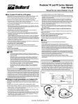
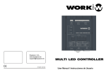
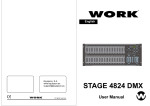
1
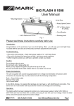
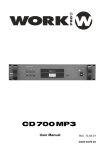
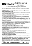
Equipson, S.A.
www.equipson.es
[email protected]
IC 4 PRO
IC 6 PRO
CEILING SPEAKERS SERIES
User Manual / Instrucciones de Usuario
CEILING SPEAKERS
ALTAVOCES DE TECHO
ENGLISH
Page 1
CASTELLANO Página 3
This symbol on the product or on its packaging indicates that this product
shall not be trated as household waste. Instead it shall be handed over to
the applicable collection point for the recycling of electrical an electronic
equipment. By ensuring this product is disposed of correctly, you will help
prevent potential negative consequences for the environment and human
health, which could otherwise be caused by inappropriate waste handling
of this product. The recycling of amterials will help to conserve natural
resources. For more detailed information sabout recycling of this product,
please contact your local city office, your household waste disposal service
or the shop where you purchased the product.
Este símbolo en su equipo o embalaje, indica que el presente producto
no puede ser tratado como residuos domésticos normales, sino que deben
entregarse en el correspondiente punto de recogida de equipos electrónicos
y eléctricos. Asegurándose de que este producto es desechado
correctamente, Ud. está ayudando a prevenir las consecuencias negativas
para el medio ambiente y la salud humana que podrían derivarse de la
incorrecta manipulación de este producto. EL reciclaje de materiales
ayuda a conservar las reservas naturales. Para recibir más información,
sobre el reciclaje de este producto, contacte con su ayuntamiento, su
punto de recogida más cercano o el distribuidor donde adquirió el producto.
IC 4/6 PRO Ceiling Speakers Series
IC 4 PRO
Especificaciones
Respuesta de frecuencia. . . . . . . . . . . . . . . . . . . . . . . . . . . . . . . . . . . . . . . . 80 Hz a 20 kHz
Impedancia . . . . . . . . . . . . . . . . . . . . . . . . . . . . . . . . . . . . . . . . . . . . . . . . . . . 8 ohms (30 W)
Sensibilidad. . . . . . . . . . . . . . . . . . . . . . . . . . . . . . . . . . . . . . . . . . . . . . . . . . . . . . . . . . . . 88 dB
Woofer. . . . . . . . . . . . . . . . . . . . . . . . . . . . . . . .4" cono de polipropileno y suspensión de goma
Tweeter. . . . . . . . . . . . . . . . . . . . . . . . . . . . . . . . . . . . . . . . . . . . . . . .0.75" montaje central.
Dimensiones. . . . . . . . . . . . . . . . . . . . . . . . . . . . . . . . . . . . . . . . . . . . 184 mm diametro x 114 mm prof
Posiciones del transformador . . . . . . . . . . . . . . . . . . . . . . . . . . . . . .70 V(8W, 4W, 2W, 1W, 0.5W)
100 V(8W, 4W, 2W, 1W)
These in-wall, or in-ceiling, speakers are designed to accurately reproduce music, including today's demanding digital signals.
In-wall speakers are designed so that the wall and the space behind it actually become the speaker cabinet. Mounted flush
to the wall, they require absolutely no floor space. The frames and grilles may be painted to blend with any decor. The
discrete, com-pact format is ideal for many applications where traditional speakers would be impractical or impossible.
In-wall speakers may be used independently where space is a consideration, or to bring music to additional rooms in the
house. They can also be used to enhance and enrich subwoofer and surround sound systems, for which they are especially
suited.
Speaker Placement
Once installed, in-wall speakers are not easily moved or repositioned. Take a little extra time to carefully consider a good
speaker location before you begin. Each room is unique, so decide what works best for you. Unlike traditional speakers,
in-walls mount flush and cannot be angled or aimed back into the listening area from the corners of a room. As a general
rule, the speakers should be mounted close to, or above, ear level, and at least one-third of the distance from the corner of
the room to the center of the wall or ceiling in which you will mount them.
1
Allow at least 1 2" of clearance between the cut out and any studs or joists for the mounting hardware to work properly.
A mounting depth of 175 mm measured from the face of the wall is also required. The speaker location and associated
mounting hardware should not conflict with any existing wires or pipes.
Hooking Up The Wires
IC 6 PRO
Especificaciones
Respuesta de frecuencia. . . . . . . . . . . . . . . . . . . . . . . . . . . . . . . . . . . . . . . . 60 Hz a 20 kHz
Impedancia . . . . . . . . . . . . . . . . . . . . . . . . . . . . . . . . . . . . . . . . . . . . . . . . . . . 8 ohms (60 W)
Sensibilidad. . . . . . . . . . . . . . . . . . . . . . . . . . . . . . . . . . . . . . . . . . . . . . . . . . . . . . . . . . . . 88 dB
Woofer. . . . . . . . . . . . . . . . . . . . . . . . . . . . . . .6.5" cono de polipropileno y suspensión de goma
Tweeter. . . . . . . . . . . . . . . . . . . . . . . . . . . . . . . . . . . . . . . . . . . . . . . .0.75" montaje central.
Dimensiones. . . . . . . . . . . . . . . . . . . . . . . . . . . . . . . . . . . . . . . . . . . . 241 mm diametro x 171 mm prof
Posiciones del transformador . . . . . . . . . . . . . . . . . . . . . . . . . . . . . .70 V(50W, 30W, 15W, 5W, 3W)
100 V(50W, 30W, 15W, 5W)
The terminals will accommodate up to 16-gauge speaker wire, which should be used for longer connections (greater than 50
feet of wire). For shorter distances, 18 or 20 gauge speaker wire will be adequate. Leave about two feet of extra wire at the
speaker end to make installation and positioning of the speaker easier. Do not use staples, nails or other metal objects to
secure the speaker wire. The resulting short circuit could affect your system's performance, and could also damage
components in your system, espe-cially the amplifier. You will get the best sound quality and least amount of hum by keeping
the speaker wires away from other electrical wires and cables.
When connecting your in-wall speaker, it is very important to retain the correct polarity. To do this, be sure that the wire
attached to the right power "top" of audio transformer on the speaker connects to the "+", red, positive or hot terminal on the
amplifier. Similarly, the "C", black, negative or ground terminal of audio transformer on the speaker must connect to the
respective "-", black, negative or ground terminal on the amplifier.
Mounting the Speaker
Yes, you will be cutting a hole in the wall. With the right tools and a little extra care and preparation, installing the in-wall
speaker can be both quick and easy. Carefully cut out the hole drawn on the paper template at the perforated edge labeled
“CUT HERE FOR MOUNTING TEMPLATE”. (Note: The inside ring on the template can be used to shield the woofer while
you paint the frame.) Next, position the template (now a border) where you have chosen to mount the speaker, and trace
along the inside edge. Make your cuts along this line. A utility knife will make the cleanest cuts in drywall. A keyhole saw or
an electric jigsaw may also be used. Try to keep the cuts neat, however the frame will overlap the hole to hide any rough
edges. At this point, with the wall open, run the speaker wires into position, and again, leave about two feet of extra wire at
the opening.
Remove the grille from the frame by pressing the quick-turn mounting screws from the back of the speaker into the grille
itself. Remove the thin piece of foam positioned under the grille, which was used to protect the speaker during
transport.
Attach the speaker wires to the speaker. With the grille removed, insert the speaker into the mounting hole. Use a phillips
head screwdriver to turn the screw slowly clockwise. The quick-turn mounting system and frame will sandwich or clamp
around the wall to hold the speaker in place. Do not overtighten. If you are unsure, consult a professional contractor.
Installing The Grille
Selector de potencia de salida
Diseño y especificaciones sujetas a cambio sin previo aviso
IC 4/6 PRO
User Manual/Manual de uso
Página 4
The metal grille, as well as the frame, may be painted to match any room. If you choose to paint them, do so before attaching
the grille to the speaker. The grille is held in place by a friction fit and is difficult to remove once the speaker is installed. If the
grille feels a little loose, or you are concerned about a grille falling from a ceiling installation, we have provided a small
amount of putty, which you can apply (sparingly) to the inside rim of the speaker before you insert the grille. The putty acts
as an additional adhesive between the grille and the frame.
IC 4/6 PRO
User Manual/Manual de uso
Page 1
IC 4/6 PRO Altavoces de Techo
IC 4 PRO
Specifications
Frequency Response. . . . . . . . . . . . . . . . . . . . . . . . . . . . . . . . . . . . . . . . 80 Hz to 20 kHz
Impedance . . . . . . . . . . . . . . . . . . . . . . . . . . . . . . . . . . . . . . . . . . . . . . . . . . . . 8 ohms (30 W)
Sensitivity. . . . . . . . . . . . . . . . . . . . . . . . . . . . . . . . . . . . . . . . . . . . . . . . . . . . . . . . . . . . . 88 dB
Woofer. . . . . . . . . . . . . . . . . . . . . . . . . . . . . . . . . .4" polypropylene cone with rubber surround
Tweeter. . . . . . . . . . . . . . . . . . . . . . . . . . . . . . . . . . . . . . . . . . . . . . . .0.75" center mounted
Dimensions. . . . . . . . . . . . . . . . . . . . . . . . . . . . . . . . . . . . . . . . . 184 mm diameter x 114 mm depth
Posiciones del transformador . . . . . . . . . . . . . . . . . . . . . . . . . . . . . .70 V(8W, 4W, 2W, 1W, 0.5W)
100 V(8W, 4W, 2W, 1W)
IC 6 PRO
Estos altavoces de techo y pared están diseñados para reproducir de manera adecuada la música reproducida, incluyendo l
a actual demanda de música digital. Los altavoces de pared están diseñados de tal manera que el espacio trasero se convierte
en la caja de resonancia del altavoz. Estos altavoces no necesitan una gran profundidad de pared para ser colocados.
Las rejillas y bordes están pintadas en blanco para integrarlo en la decoración. Este formato compacto y discreto es ideal
para multitud de aplicaciones donde el altavoz tradicional no pueda ser colocado y para ambientar habitaciones, salas u
oficinas. Tambien pueden ser usados para realzar los sistemas de sonorización.
Colocación del altavoz
Una vez instalado el altavoz, no es fácil moverlo o recolocarlo. Tómese su tiempo para elegir cuidadosamente el lugar de
instalación. Cada habitación es única, así que decida la mejor ubicación al resultado que desea conseguir. Al contrario que
los altavoces tradicionales, estos altavoces de pared no pueden ser colocados en ángulo o aprovechar su rebote en esquinas
etc. Como norma general, estos altavoces deben ser colocados cerca o a nivel del oido y al menos a una distancia de un
tercio desde la esquina al centro de la habitación.
Deje, al menos, 1.5” de separación entre el corte y elementos como vigas u otros sistemas de techo o pared para poder trabajar
con facilidad a la hora de instalar. Se requiere asimismo una profundidad de al menos 175 mm. La localización del altavoz y
elementos asociados, no debe entrar en conflicto con sistemas de cables o tuberías ya existentes.
Specifications
Frequency Response. . . . . . . . . . . . . . . . . . . . . . . . . . . . . . . . . . . . . . . . 60 Hz to 20 kHz
Conectando los cables
Impedance . . . . . . . . . . . . . . . . . . . . . . . . . . . . . . . . . . . . . . . . . . . . . . . . . . . 8 ohms (60 W)
Sensitivity. . . . . . . . . . . . . . . . . . . . . . . . . . . . . . . . . . . . . . . . . . . . . . . . . . . . . . . . . . . . . 88 dB
Woofer. . . . . . . . . . . . . . . . . . . . . . . . . . . . . . . . . .6.5" polypropylene cone with rubber surround
Tweeter. . . . . . . . . . . . . . . . . . . . . . . . . . . . . . . . . . . . . . . . . . . . . . . .3/4" center mounted
Dimensions. . . . . . . . . . . . . . . . . . . . . . . . . . . . . . . . . . . . . . . . . 241 mm diameter x 171 mm depth
Posiciones del transformador . . . . . . . . . . . . . . . . . . . . . . . . . . . . . .70 V(50W, 30W, 15W, 5W, 3W)
100 V(50W, 30W, 15W, 5W)
Los terminales se conectan a un cable de altavoz de 16 gauge, el cual debe ser usado para conexiones largas (Mayores de
15 m), para conexiones menores los cable 18 o 20 gauge son adecuados. Deje al menos unos 60 cm. de cable para facilitar
el instalación y posicionar el altavoz. No use grapas o clavos para sujetar el cable de altavoz. Usar estos elementos metálicos
podría cortocircuitar los cables y afectar al rendimiento del altavoz, dañando incluso los amplificadores. Obtendrá un mejor
rendimiento con un sonido libre de zumbidos y ruidos si aleja los cables de altavoz de los cables eléctricos.
Cuando conecte el altavoz es importante respetar la polaridad. Para ello asegúrese que el cable marcado como “top” se
conecta al “+” o cable rojo del amplificador. De igual manera el cable “C” negro o negativo, debe conectarse al terminal “-”
, masa o negro del amplificador.
Montando el altavoz
Ahora debe realizar el corte en la pared o techo con la plantilla adjunta y con la herramienta adecuada y tomándose su tiempo.
Corte con cuidado por la linea de puntos marcada como “CUT HERE FOR MOUNTING TEMPLATE” (Nota: el aro interno
puede ser usado para para proteger el altavoz en caso de necesitar pintar el marco). Ahora posicione la plantilla en el lugar
elegido para el montaje. Dibuje el circulo resultante. Haga el corte por esta línea. Puede utilizar un cuchillo, o cualquier tipo
de cortante. Trate de realizar un corte limpio. En este punto, con el hueco realizado, coloque los cables hasta la posición,
dejando al menos unos 40 cm de cable libre.
Retire la rejilla del marco presionando desde la parte trasera del altavoz. Retire la pieza fina de espuma bajo la rejilla, la cual
se usa para proteger el altavoz durante el transporte.
Conecte los cables al altavoz. Con la rejilla quitada, inserte el altavoz en el agujero. Use un destornillador para apretar los
tornillos lentamente. El sistema de fijación y el marco, se insertarán alrededor del agujero hecho, manteniendo el altavoz
en su sitio. No fuerce su fijación.
Power Output selector
Design and specifications are subject to change without notice.
Instalando la Rejilla
La rejilla de metal, así como el marco pueden pintarse para integrarlo en la decoración de la sala. Si elije pintarlo, hágalo, antes
de colocar la rejilla al altavoz. La rejilla se fija con un sistema de fricción con lo cual es dificil de retirar una vez instalado el
altavoz. Si la rejilla pierde adherencia al altavoz o se desprende, es mejor utilizar un poco de masilla en el interior antes de
fijar la rejilla. La masilla actúa como un adhesivo entre la rejilla y el marco.
IC 4/6 PRO
User Manual/Manual de uso
Page 2
IC 4/6 PRO
User Manual/Manual de uso
Página 3