1
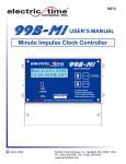
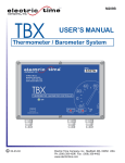
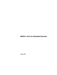
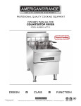
M344
99b-mi
OUTPUT BOARD
Installation Manual
12-04-2009
Electric Time Company, inc. Medfield, MA 02052 USA
Ph: (508) 359-4396 Fax: (508) 359-4482
www.electrictime.com
M344
Pg. 2 of 13
INTRODUCTION
The 99B-MI Clock Controller with relay adapter box is a microprocessor based
master clock that provides completely automatic control of minute impulse
(MI), stepper corrective (SC), dual synchronous motor (DM), single
synchronous motor (STOP) and National Time dual synchronous motor (NAT)
clocks. This manual provides installation instructions for connecting the
various clock types and configuring the 99BMI. Refer to M274 for complete
99BMI operation instructions.
TABLE OF CONTENTS
CTRL-99BMI-MI-115 ............................................................................. 3
CTRL-99BMI-SC ................................................................................... 5
CTRL-99BMI-DM ................................................................................... 7
CTRL-99BMI-STOP ............................................................................... 9
CTRL-99BMI-NAT ................................................................................. 11
SERVICE ............................................................................................... 13
12-04-2009
Electric Time Company, inc. Medfield, MA 02052 USA
Ph: (508) 359-4396 Fax: (508) 359-4482
www.electrictime.com
M344
Pg. 3 of 13
CONNECTING “MI-115 CLOCKS”
(Minute Impulse, 115VAC)
SS HR
MI CLOCK 1
C
G L1 L2 C
1. If the adapter box is not already prewired to the
99BMI clock controller connect L1, L2, C and HR (hour
strike) from the 99BMI to the relay board (18ga
recommended).
TO RELAY CIRCUIT
BOARD
POWER IN
G
2. Connect the power output wiring from the adapter box
to the 99BMI.
L
N
115VAC/60Hz/1A
115 VAC POWER
OUT
1X (NORMAL)
G
N
10X (RESET)
L
G
115VAC/60Hz/5A
N
L
115VAC/60Hz/5A
3. Connect L1, L2 and C movement wiring to L (1X) and
L (10X) and N on the relay board.
For multiple clocks, “Home Run” wiring is required
between each clock and one of the “MI CLOCK” outputs
on 99B-MI
G L1 L2 C
MI CLOCK 1
HOUR STRIKE
G
N
L
115VAC/60Hz/5A
115 VAC BELL
STRIKE
12-04-2009
4. Connect Hour Strike output if equipped. Refer to
99BMI user manual M274 for hour strike configuration
details.
5. Connect 115Vac input power to the “Power In”
location on the relay board.
Electric Time Company, inc. Medfield, MA 02052 USA
Ph: (508) 359-4396 Fax: (508) 359-4482
www.electrictime.com
M344
Pg. 4 of 13
MI-115 CLOCK OPERATION
(Minute Impulse, 115VAC)
Using the relay adapter box with 99BMI controller 115Vac MI clock movements will
function per 99BMI user manual M274. Refer to M274 for all functions including
correcting time, date and clock hand position.
SPECIAL SETUP FUNCTIONS (tech mode)
“L1/L2 Drive Opt:”
! Minute Impulse: For MI style clocks
! None: Turns L1 and L2 function off
! SC Pulsed: Stepper Corrective movements,
L 1/L 2 D rive O p t :
Minu te I m pul s e
minutes corrected every hour, hour corrected
twice a day
! Dual Motor: L1-normal motor, L2-reset motor, L1
& L2 operate on reset
! Dual Motor NAT: L1-normal motor, L2-reset motor,
L2 only on reset
! Dual Motor Stop: L1-normal motor. No reset
motor.
12-04-2009
Electric Time Company, inc. Medfield, MA 02052 USA
Ph: (508) 359-4396 Fax: (508) 359-4482
www.electrictime.com
M344
Pg. 5 of 13
CONNECTING “SC-115 CLOCKS”
(Stepper Corrective, 115VAC)
NOTE: 24Vac Stepper corrective systems do not require
SS HR
MI CLOCK 1
an adapter box. Connect ‘L1’ to movement ‘L’ (line), ‘L2’
C
G L1 L2 C
connects to movement ‘S’ (synch) and ‘C’ connects to ‘N’
(neutral).
TO RELAY CIRCUIT
BOARD
1. If the adapter box is not already prewired to the
99BMI clock controller connect L1, L2, C and HR (hour
strike) from the 99BMI to the relay board (18ga
recommended).
POWER IN
G
L
N
115VAC/60Hz/1A
2. Connect the power output wiring from the adapter box
to the 99BMI.
115 VAC POWER
OUT
1X (NORMAL)
G
N
10X (RESET)
L
G
115VAC/60Hz/5A
G
N
L
115VAC/60Hz/5A
L
S N
3. Connect L (line), S (synch) and N (neutral) movement
wiring to L (1X) and L (10X) and N respectively on the
relay board.
For multiple clocks, “Home Run” wiring is required
between each clock and one of the “MI CLOCK” outputs
on 99B-MI
SC CLOCK 1
HOUR STRIKE
G
N
L
115VAC/60Hz/5A
115 VAC BELL
STRIKE
12-04-2009
4. Connect Hour Strike output if equipped. Refer to
99BMI user manual M274 for hour strike configuration
details.
5. Connect 115Vac input power to the “Power In”
location on the relay board.
Electric Time Company, inc. Medfield, MA 02052 USA
Ph: (508) 359-4396 Fax: (508) 359-4482
www.electrictime.com
M344
Pg. 6 of 13
SC-115 CLOCK OPERATION
(Stepper Corrective, 115VAC)
Using the relay adapter box with 99BMI controller, 115Vac SC clock movements will
function normally through the 99BMI. Some function are not possible with stepper
corrective movements. Refer to M274 to set the time and date.
SPECIAL SETUP FUNCTIONS (tech mode)
“L1/L2 Drive Opt:”
! Minute Impulse: For MI style clocks
! None: Turns L1 and L2 function off
! SC Pulsed: Stepper Corrective movements,
L 1/L 2 D rive O p t :
SC Pulsed
minutes corrected every hour, hour corrected
twice a day
! Dual Motor: L1-normal motor, L2-reset motor, L1
& L2 operate on reset
! Dual Motor NAT: L1-normal motor, L2-reset motor,
L2 only on reset
! Dual Motor Stop: L1-normal motor. No reset
motor.
“Advance Hands?”
! Send 12 Hour : Sends 12 hour pulse, Hour hand
advances to 6:00
! Send Hour: Sends hour pulse. Minute hand
advances to 12:00 position
12-04-2009
A dva n c e H a n d s ?
Send 12 Hour
Electric Time Company, inc. Medfield, MA 02052 USA
Ph: (508) 359-4396 Fax: (508) 359-4482
www.electrictime.com
M344
Pg. 7 of 13
CONNECTING “DM” Clocks
(Dual Motor, 115VAC)
SS HR
MI CLOCK 1
C
G L1 L2 C
1. If the adapter box is not already prewired to the
99BMI clock controller connect L1, L2, C and HR (hour
strike) from the 99BMI to the relay board (18ga
recommended).
TO RELAY CIRCUIT
BOARD
POWER IN
G
2. Connect the power output wiring from the adapter box
to the 99BMI.
L
N
115VAC/60Hz/1A
115 VAC POWER
OUT
1X (NORMAL)
G
N
10X (RESET)
L
G
115VAC/60Hz/5A
N
L
115VAC/60Hz/5A
3. Connect the normal and reset motors to the adapter
box.
For multiple clocks, “Home Run” wiring is required
between each clock and the adapter box
NORMAL
MOTOR
RESET
MOTOR
HOUR STRIKE
G
N
L
115VAC/60Hz/5A
115 VAC BELL
STRIKE
12-04-2009
4. Connect Hour Strike output if equipped. Refer to
99BMI user manual M274 for hour strike configuration
details.
5. Connect 115Vac input power to the “Power In”
location on the relay board.
Electric Time Company, inc. Medfield, MA 02052 USA
Ph: (508) 359-4396 Fax: (508) 359-4482
www.electrictime.com
M344
Pg. 8 of 13
DM CLOCK OPERATION
(Dual Motor, 115VAC)
Using the relay adapter box with 99BMI controller 115Vac Dual Motor clock
movements will function per 99BMI user manual M274. Refer to M274 for all functions
including setting time, date and correcting the clock hands.
SPECIAL SETUP FUNCTIONS (tech mode)
“L1/L2 Drive Opt:”
! Minute Impulse: For MI style clocks
! None: Turns L1 and L2 function off
! SC Pulsed: Stepper Corrective movements,
L 1/L 2 D rive O p t :
Dual Motor
minutes corrected every hour, hour corrected
twice a day
! Dual Motor: L1-normal motor, L2-reset motor, L1
& L2 operate on reset
! Dual Motor NAT: L1-normal motor, L2-reset motor,
L2 only on reset
! Dual Motor Stop: L1-normal motor. No reset
motor.
12-04-2009
Electric Time Company, inc. Medfield, MA 02052 USA
Ph: (508) 359-4396 Fax: (508) 359-4482
www.electrictime.com
M344
Pg. 9 of 13
CONNECTING Single Motor “STOP” Clocks
(Single Motor, 115VAC)
SS HR
MI CLOCK 1
C
G L1 L2 C
1. If the adapter box is not already prewired to the
99BMI clock controller connect L1, L2, C and HR (hour
strike) from the 99BMI to the relay board (18ga
recommended).
TO RELAY CIRCUIT
BOARD
POWER IN
G
2. Connect the power output wiring from the adapter box
to the 99BMI.
L
N
115VAC/60Hz/1A
115 VAC POWER
OUT
1X (NORMAL)
G
L
N
G L
115VAC/60Hz/5A
3. Connect the normal motor to the adapter box.
For multiple clocks, “Home Run” wiring is required
between each clock and the adapter box
NORMAL
MOTOR
HOUR STRIKE
G
N
L
115VAC/60Hz/5A
4. Connect Hour Strike output if equipped. Refer to
99BMI user manual M274 for hour strike configuration
details.
5. Connect 115Vac input power to the “Power In”
location on the relay board.
115 VAC BELL
STRIKE
12-04-2009
Electric Time Company, inc. Medfield, MA 02052 USA
Ph: (508) 359-4396 Fax: (508) 359-4482
www.electrictime.com
M344
Pg. 10 of 13
‘STOP’ CLOCK OPERATION
(Single Motor, 115VAC)
Using the relay adapter box with 99BMI controller 115Vac Single Motor clock
movements will function per 99BMI user manual M274. Refer to M274 for all functions
including setting time, date and correcting the clock hands.
Note: The hands will not move when the hand position does not match the current
time. The Stop function waits up to 12 hours for the hands and current time to match
before resuming normal operation
SPECIAL SETUP FUNCTIONS (tech mode)
“L1/L2 Drive Opt:”
! Minute Impulse: For MI style clocks
! None: Turns L1 and L2 function off
! SC Pulsed: Stepper Corrective movements,
L 1/L 2 D rive O p t :
D u al Mo to r S t op
minutes corrected every hour, hour corrected
twice a day
! Dual Motor: L1-normal motor, L2-reset motor, L1
& L2 operate on reset
! Dual Motor NAT: L1-normal motor, L2-reset motor,
L2 only on reset
! Dual Motor Stop: L1-normal motor. No reset
motor.
12-04-2009
Electric Time Company, inc. Medfield, MA 02052 USA
Ph: (508) 359-4396 Fax: (508) 359-4482
www.electrictime.com
M344
Pg. 11 of 13
CONNECTING NATIONAL TIME “NAT” Clocks
(Dual Motor National Time, 115VAC)
SS HR
MI CLOCK 1
C
G L1 L2 C
1. If the adapter box is not already prewired to the
99BMI clock controller connect L1, L2, C and HR (hour
strike) from the 99BMI to the relay board (18ga
recommended).
TO RELAY CIRCUIT
BOARD
POWER IN
G
2. Connect the power output wiring from the adapter box
to the 99BMI.
L
N
115VAC/60Hz/1A
115 VAC POWER
OUT
1X (NORMAL)
G
N
10X (RESET)
L
G
115VAC/60Hz/5A
N
L
115VAC/60Hz/5A
3. Connect the normal and reset motors to the adapter
box.
For multiple clocks, “Home Run” wiring is required
between each clock and the adapter box
NORMAL
MOTOR
RESET
MOTOR
HOUR STRIKE
G
N
L
115VAC/60Hz/5A
115 VAC BELL
STRIKE
12-04-2009
4. Connect Hour Strike output if equipped. Refer to
99BMI user manual M274 for hour strike configuration
details.
5. Connect 115Vac input power to the “Power In”
location on the relay board.
Electric Time Company, inc. Medfield, MA 02052 USA
Ph: (508) 359-4396 Fax: (508) 359-4482
www.electrictime.com
M344
Pg. 12 of 13
‘NAT’ CLOCK OPERATION
(Dual Motor National Time, 115VAC)
Using the relay adapter box with 99BMI controller 115Vac Dual Motor National Time
clock movements will function per 99BMI user manual M274. Refer to M274 for all
functions including setting time, date and correcting the clock hands.
SPECIAL SETUP FUNCTIONS (tech mode)
“L1/L2 Drive Opt:”
! Minute Impulse: For MI style clocks
! None: Turns L1 and L2 function off
! SC Pulsed: Stepper Corrective movements,
L 1/L 2 D rive O p t :
D u a l M o t o r NAT
minutes corrected every hour, hour corrected
twice a day
! Dual Motor: L1-normal motor, L2-reset motor, L1
& L2 operate on reset
! Dual Motor NAT: L1-normal motor, L2-reset
motor, L2 only on reset
! Dual Motor Stop: L1-normal motor. No reset
motor.
12-04-2009
Electric Time Company, inc. Medfield, MA 02052 USA
Ph: (508) 359-4396 Fax: (508) 359-4482
www.electrictime.com
M344
Pg. 13 of 13
SERVICE
For assistance in troubleshooting problems, or to request service, contact the Electric
Time Company Service Department at the address shown below:
Electric Time Company, inc.
Service Department
97 West Street
Medfield, MA 02052 USA
Ph: (508) 359-4396
Fax: (508) 359-4482
Email: [email protected]
12-04-2009
Electric Time Company, inc. Medfield, MA 02052 USA
Ph: (508) 359-4396 Fax: (508) 359-4482
www.electrictime.com