Download User Manual M209B - Electric Time Company, Inc
Transcript
M209B
TBX
USER’S MANUAL
Thermometer / Barometer System
616TA
04-23-04
Electric Time Company, inc. Medfield, MA 02052 USA
Ph: (508) 359-4396 Fax: (508) 359-4482
www.electrictime.com
M209B
Pg. 2 of 12
TABLE OF CONTENTS
QUICK START GUIDE .......................................................................... 3
INTRODUCTION ................................................................................... 6
SPECIFICATIONS ................................................................................. 6
TERMINAL COMPARTMENT LAYOUT................................................. 7
FEATURES..............................................................................................8
OPERATION........................................................................................... 8
DEVICE ADDRESSES............................................................................9
TROUBLESHOOTING............................................................................ 10
CALIBRATION PROCEDURE................................................................ 11
SERVICE.................................................................................................12
WIRING DIAGRAMS.............................................................................. A-5661
04-23-04
Electric Time Company, inc. Medfield, MA 02052 USA
Ph: (508) 359-4396 Fax: (508) 359-4482
www.electrictime.com
M209B
Pg. 3 of 12
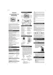
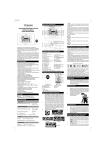
QUICK START GUIDE
1) DISCONNECT 115VAC POWER CIRCUIT BEFORE
MAKING ANY WIRING CONNECTIONS
2) INSTALL ALL THERMOMETER OR BAROMETER
DIALS
! IF POINTERS WERE PROVIDED SEPARATELY, DO NOT
INSTALL THEM YET
! IF POINTERS ARE ALREADY INSTALLED, JUST GO ON
TO STEP (3) BELOW
3) INSTALL TBX CONTROLLER IN ACCESSIBLE
LOCATION (#10 SCREWS RECOMMENDED)
4) MOUNT TEMPERATURE SENSOR ASSEMBLY
(THERMOMETERS ONLY)
TEMP. SENSOR
S
+
-
!
!
!
!
!
!
½”NPT FITTING WITH NUT PROVIDED FOR MOUNTING
50’ CABLE PROVIDED WITH SENSOR ASSEMBLY
CLASS II SIGNAL CABLE - FOLLOW LOCAL CODES
OBSERVE POLARITY AS SPECIFIED
LOCATE SENSOR IN OPEN AIR
DO NOT LOCATE IN DIRECT SUNLIGHT OR NEAR
HEATING OR COOLING EQUIPMENT
SHIELD
5) CONNECT TEMPERATURE SENSOR TO TBX
CONTROLLER
FROM TEMP. SENSOR
04-23-04
Electric Time Company, inc. Medfield, MA 02052 USA
Ph: (508) 359-4396 Fax: (508) 359-4482
www.electrictime.com
M209B
Pg. 4 of 12
QUICK START GUIDE
MOVEMENT
S A
B
+
-
6) CONNECT TBX CONTROLLER TO DIALS
(24VDC - 16AWG RECOMMENDED)
! CONNECT SHIELD TO CONTROLLER ONLY
! CONNECT MULTIPLE DIALS IN PARALLEL
SHIELD
TO CIRCUIT BOARD
ON MOVEMENT
POWER IN
G
N
L
115VAC/60Hz/1A
7) CONNECT DEDICATED 115VAC BRANCH CIRCUIT
TO TBX CONTROLLER
8) TURN ON 115VAC POWER
115 VAC DEDICATED
BRANCH CIRCUIT
! IF YOUR THERMOMETER DIALS WERE PROVIDED
WITH POINTERS ALREADY INSTALLED, SKIP TO STEP
(12)
HOME
9) INSIDE TBX CONTROLLER, PRESS “HOME”
BUTTON ONCE
WAIT
! WAIT AT LEAST 60 SECONDS BEFORE PROCEEDING
TO STEP 9
10) IF POINTER WAS PROVIDED SEPARATELY,
INSTALL POINTER ONTO DIAL POINTING TO
LOWEST READING ON DIAL (-20~F SHOWN)
04-23-04
Electric Time Company, inc. Medfield, MA 02052 USA
Ph: (508) 359-4396 Fax: (508) 359-4482
www.electrictime.com
M209B
Pg. 5 of 12
QUICK START GUIDE
HOME
11) INSIDE TBX CONTROLLER, PRESS “HOME”
BUTTON ONE MORE TIME
12) THERMOMETER WILL AUTOMATICALLY RESET
ITSELF TO CORRECT TEMPERATURE
04-23-04
Electric Time Company, inc. Medfield, MA 02052 USA
Ph: (508) 359-4396 Fax: (508) 359-4482
www.electrictime.com
M209B
Pg. 6 of 12
INTRODUCTION
The TBX Thermometer / Barometer System is comprised of a microprocessor
based controller and a step-motor driven movement that provide accurate,
completely automatic indication of Temperature or Barometric Pressure.
!
!
!
!
Completely automatic operation - No user intervention required
Maintenance free
Automatically resets after power failures to ensure correct readings
For indoor or outdoor use - Protected to Ip67
SPECIFICATIONS
Power Requirements
24VAC/50-60 Hz/1.67A (Plug-in Wall Transformer Provided)
Accuracy
+/- 1.5 ~F
Inputs
Temperature Sensor
! 3 Position Screw Terminal Connection
! 2 Terminals = Sensor Signal
! 1 Terminal = Shield Wire
Barometer Sensor
! Factory installed directly onto PC Board
Outputs
Thermometer / Barometer Control Signal
! 5 Position Screw Terminal Connection
! 2 Terminals = 24VDC
! 2 Terminals = RS-485 Communication
! 1 Terminal = Shield Wire
**Controls up to (2) Thermometers or Barometers total
Communication
RS-232
! Factory programming and setup (DB9 Connector)
RS-485
! Auxiliary communication port (3 Position Screw Terminal)
04-23-04
Electric Time Company, inc. Medfield, MA 02052 USA
Ph: (508) 359-4396 Fax: (508) 359-4482
www.electrictime.com
M209B
Pg. 7 of 12
POWER INPUT
(24VAC PLUG-IN
WALL TRANSORMER
PROVIDED)
TEMPERATURE
SENSOR INPUT
MOVEMENT CONTROL
SIGNALS
Terminal Compartment Layout
04-23-04
Electric Time Company, inc. Medfield, MA 02052 USA
Ph: (508) 359-4396 Fax: (508) 359-4482
www.electrictime.com
M209B
Pg. 8 of 12
FEATURES
1) LED’s
! POWER: Illuminates to Indicate Input Power is OK
! HEART BEAT: Blinks to indicate processor is functioning properly
! TEMP SENS: Indicates Temperature Sensor is connected
! BARO SENS: Indicates Barometer Sensor is installed on PC Board
! 1 - 16: Indicate RS-485 Device Address of connected movements
(See Table 1 - Pg. 9)
2) “HOME” Button
! Press once to send movement to its home index position
! Press again to resume normal operation
! Typically used to send movement to “home” position before installing pointer
3) “FULL SCALE” Button
! Press once to send movement to its full-scale reading
! Press again to resume normal operation
! Typically used to verify that movement is operating normally
OPERATION
The TBX Controller is setup and calibrated at the factory to provide years of
maintenance-free, accurate temperature / barometric pressure indication. After
installing a Thermometer or Barometer per the setup instructions provided, the unit
operates as follows:
! TBX reads Temperature Sensor or Barometric Pressure Sensor
! TBX converts reading to a known angular pointer position on display dial
! TBX sends command signal (via RS-485) to movement to drive pointer to correct
position
! TBX repeats this process continually to constantly update pointer position as
required
! After power outage, TBX will command movement to reindex (go to “HOME”
position) and then bring pointer back to correct position to ensure accuracy of
display
04-23-04
Electric Time Company, inc. Medfield, MA 02052 USA
Ph: (508) 359-4396 Fax: (508) 359-4482
www.electrictime.com
M209B
Pg. 9 of 12
DEVICE ADDRESSES
Any Thermometer / Barometer movement that is connected to the TBX
Controller will have a unique address such that the TBX Controller can send different
commands (via RS-485) to specific movements depending upon their address. In
this way, one TBX Controller can control a Thermometer and Barometer
simultaneously (or two Thermometers with different temperature scales, etc.). The
status LED’s inside the TBX indicate what addresses are being used by movements
that are connected to the controller. Not only does this indicate that a movement is
connected (helpul when troubleshooting) but it also tells what type of movement is
connected. Using the following table it is possible to determine what type of
movement is connected to the control based upon its address.
Address
Type of Movement
1
Customizable
2
Customizable
3
Customizable
4
Customizable
5
HMI Thermometer
6
HMI Thermometer
7
B28 Thermometer
8
B28 Thermometer
9
A
B
C
D
0
HMI Barometer
HMI Barometer
B28 Barometer
B28 Barometer
C1 Thermometer
C1 Thermometer
Table 1
04-23-04
Electric Time Company, inc. Medfield, MA 02052 USA
Ph: (508) 359-4396 Fax: (508) 359-4482
www.electrictime.com
M209B
Pg.10 of 12
TROUBLESHOOTING
“MY THERMOMETER / BAROMETER IS NOT CORRECT”
! Pointer still moves, but readings shown are not correct
1) Send the Pointer to “HOME” position
!
!
!
!
Inside TBX Controller, press “HOME” button once
Look at dial: Pointer should point to lowest reading on dial and stop (ex. -20~F)
If Pointer is NOT pointing to lowest reading on dial, it must be adjusted manually
Remove pointer from movement shaft and follow instructions in “Quick Start
Guide” for proper setup of Thermometer / Barometer systems
! If Pointer IS pointing to lowest reading on dial, see “Calibration Procedure” on
Page 11 to calibrate the thermometer
“MY THERMOMETER / BAROMETER DOESN’T MOVE”
1) Check AC Power Input
!
!
Inside TBX Controller, is POWER LED illuminated?
If not, have an electrician check circuit breakers or building electrical supply
2) Check Temperature Sensor (for Thermometer Systems only)
!
!
!
!
!
Inside TBX Controller, is Temperature Sensor connected?
If not, reconnect sensor and hit “HOME” button once to re-index the thermometer
WAIT 60 Seconds, then hit “HOME” button again to resume operation
Is Pointer showing correct temperature?
If not, contact Electric Time Company for service
3) Is movement(s) connected to TBX Controller?
!
!
!
Inside TBX Controller, are any address LED’s illuminated (numbers 1-16)?
If not, check all wiring connections to movement
If all wiring connections are OK, contact Electric Time Company for service
04-23-04
Electric Time Company, inc. Medfield, MA 02052 USA
Ph: (508) 359-4396 Fax: (508) 359-4482
www.electrictime.com
M209B
Pg. 11 of 12
TROUBLESHOOTING
CALIBRATION PROCEDURE
If the thermometer or barometer is operating, but does not indicate the correct reading,
the following calibration procedure can be used to set the thermometer/barometer to the
correct reading
CAUTION: The following calibration procedure requires opening the TBX Controller
while it is powered. Although the supply voltage to the controller is typically only
24VAC or 24VDC, this procedure should only be performed by a qualified technician
or electrician.
! With the thermometer operating normally, remove the cover to the TBX Controller
Housing
! At the top edge of the circuit board near the middle of the board is a vertical row of
2-pin headers (identified as JP4 on the circuit board) and labeled THERM, BARO,
CLEAR, & PARK
! There is a small black jumper located in the PARK position
! Move this jumper to the THERM or BARO position to enter calibration mode for
either a Thermometer or Barometer respectively
! With the jumper in place, locate the adjustment potentiometer (identified as R39
on the circuit board) and labeled ADJUST
! Using a small screw driver, slowly turn the ADJUST potentiometer
! The pointer on the Thermometer / Barometer dial will move as the potentiometer
is turned
! Turn the potentiometer until the pointer indicates the correct temperature or
barometeric pressure as required
! When the pointer indicates the correct reading on the dial, remove the jumper
from the calibration position and return it to the PARK position for storage
04-23-04
Electric Time Company, inc. Medfield, MA 02052 USA
Ph: (508) 359-4396 Fax: (508) 359-4482
www.electrictime.com
M209B
Pg. 12 of 12
SERVICE
For assistance in troubleshooting problems with your TBX Controller, or to request
service, contact the Electric Time Company Service Department at the address shown
below:
Electric Time Company, inc.
Service Department
45 West Street
Medfield, MA 02052 USA
Ph: (508) 359-4396
Fax: (508) 359-4482
Email: [email protected]
REVISION HISTORY
12-11-03
04-23-04
04-23-04
Revision A - Manual for new TBX System
Revision B - Changed enclosure for easier wiring
- added “Time movements” to addresses 1-4
- Changed movement addresses.
Electric Time Company, inc. Medfield, MA 02052 USA
Ph: (508) 359-4396 Fax: (508) 359-4482
www.electrictime.com
2
1
B
B
MOVEMENT WIRING
(4) WIRE + SHIELD
(16AWG RECOMMENDED)
(A) - WHITE
(B) - GREEN
(+) - RED
(-) - BLACK
24VAC 50/60-HZ 1.67A
(PLUG-IN TRANSFORMER
PROVIDED)
A
NOTES:
- TEMPERATURE SENSOR TO BE
MOUNTED IN OPEN AIR, OUT OF
DIRECT SUNLIGHT, AND AWAY
FROM HEATING AND COOLING
EQUIPMENT
- ADDITIONAL THERMOMETERS
OR BAROMETERS TO BE WIRED IN
PARALLEL
TEMPERATURE SENSOR WIRING
(2) WIRE + SHIELD
(50' PROVIDED; 300' MAX)
(+) - RED
(-) - BLACK
ENCL-TBX
UNLESS OTHERWISE SPECIFIED:
ALL DIMENSIONS IN INCHES
TOLERACES ON DECIMAL DIMENSIONS:
.X `.031
.XX `.01
NONE
APPROVALS
DRAWN
.XXX `.005
DO NOT SCALE DRAWING
MATERIAL
ENGINEER
THA
THA
DATE
company, inc
7-13-2004
TITLE
FINISH
NONE
medfield, ma
WIRING DIAGRAM
CTRL-TBX
TREATMENT
NONE
2
1/2" NPT
SIZE SCALE:
A
NONE
DWG. NO.
A-5661
M:\INVENTOR\DRAWINGS\A-5661.idw
1
REV.
SHEET 1
A
Medfield, MA 02052 USA
Ph: (508) 359-4396 Fax: (508) 359-4482
www.electrictime.com


