1
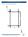
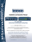
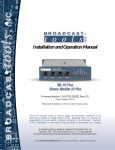
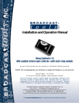
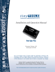
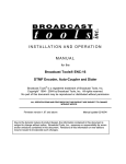
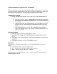
INC
®
PROBLEM SOLVED
Installation and Operation Manual
Mixer Buddy
Manual update: Manual update: 03/28/2012
No part of this document may be reproduced or distributed without permission.
ALL SPECIFICATIONS AND FEATURES FOR THIS PRODUCT ARE SUBJECT TO
CHANGE WITHOUT NOTICE
Due to the dynamic nature of product design, the information contained in this
document is subject to change without notice. Broadcast Tools, Inc., assumes no
responsibility for errors and/or omissions contained in this document. Revisions
of this information or new editions may be issued to incorporate such changes.
Broadcast Tools® is a registered trademark of Broadcast Tools, Inc.
tiny TOOLS™ is a trademark of Broadcast Tools, Inc.
All Sentinel® labeled products are registered trademarks of Broadcast Tools, Inc.
Copyright® 1989 - 2012 by Broadcast Tools, Inc. All rights reserved.
No part of this document may be reproduced or distributed without permission.
Visit www.broadcasttools.com for important product update information.
Mixer Buddy Installation and Operation Manual
Table of Contents
Section Title
Page #
Introduction . . . . . . . . . . . . . . . . . . . . . . . . . . . . . . . . . . . . . . . . . . . . . 3
Safety Information . . . . . . . . . . . . . . . . . . . . . . . . . . . . . . . . . . . . . . . . 3
Who to Contact for Help . . . . . . . . . . . . . . . . . . . . . . . . . . . . . . . . . . . 3
Product Overview . . . . . . . . . . . . . . . . . . . . . . . . . . . . . . . . . . . . . . . . 4
Inspection . . . . . . . . . . . . . . . . . . . . . . . . . . . . . . . . . . . . . . . . . . . . . . . 4
Installation . . . . . . . . . . . . . . . . . . . . . . . . . . . . . . . . . . . . . . . . . . . . . . 4
Surge Protection . . . . . . . . . . . . . . . . . . . . . . . . . . . . . . . . . . . . . . . 4
UPS Standby Power System . . . . . . . . . . . . . . . . . . . . . . . . . . . . . 4
Microphone Insert connections. . . . . . . . . . . . . . . . . . . . . . . . . . . . 4
Monitor audio connections . . . . . . . . . . . . . . . . . . . . . . . . . . . . . . 5
On-Air light relay . . . . . . . . . . . . . . . . . . . . . . . . . . . . . . . . . . . . . . 6
Monitor mute programming . . . . . . . . . . . . . . . . . . . . . . . . . . . . . . 6
Operation . . . . . . . . . . . . . . . . . . . . . . . . . . . . . . . . . . . . . . . . . . . . . . . 6
Specifications . . . . . . . . . . . . . . . . . . . . . . . . . . . . . . . . . . . . . . . . . . . . 7
Counter-top and/or turret mounting instructions . . . . . . . . . . . . . . . . . 7
Warranty. . . . . . . . . . . . . . . . . . . . . . . . . . . . . . . . . . . . . . . . . . . . . . . . 8
Fractional Schematic . . . . . . . . . . . . . . . . . . . . . . . . . . . . . . . Appendix
Connector label . . . . . . . . . . . . . . . . . . . . . . . . . . . . . . . . . . . Appendix
Front panel layout . . . . . . . . . . . . . . . . . . . . . . . . . . . . . . . . . Appendix
Counter-top and/or turret mounting template . . . . . . . . . . . . Appendix
WEBSITE:
Visit our web site for
product updates and
additional information.
CONTENTS
e-mail: [email protected] voice: 360.854.9559 fax: 866.783.1742
2
Mixer Buddy Installation and Operation Manual
INTRODUCTION
Thank you for your purchase of a Broadcast Tools® Mixer Buddy is a four
channel microphone and monitor controller (referred to as the Mixer Buddy
throughout this manual). We’re confident that this product will give you many years
of dependable service. This manual is intended to give you all the information needed to install and operate the Mixer Buddy.
SAFETY INFORMATION
Only qualified technical personnel should install the Mixer Buddy. Any
attempt to install this device by a person who is not technically qualified could result
in a hazardous condition to the installer or other personnel or damage to the Mixer
Buddy or other equipment. Please ensure that proper safety precautions have been
taken before installing this device. If you are unfamiliar with this type of equipment,
please contact a properly qualified engineer to handle the installation and setup of
the Mixer Buddy.
Broadcast Tools, Inc., is unable to support NON-Broadcast Tools software, hardware or NON-Broadcast Tools computer/hardware/software problems. If you experience
these problems, please research your hardware/software instruction manuals or contact the
manufacturers technical support department.
CAUTION!
Broadcast Tools®
Products, as with any
electronic device, can
fail without warning.
Do not use this product
in applications where a
life threatening condition
could result due to failure.
NOTE:
This manual should be
read thoroughly before
installation and operation.
WHO TO CONTACT FOR HELP
If you have any questions regarding your product or you need assistance, please contact your distributor from whom you purchased this equipment.
If you would like more information about Broadcast Tools® products, you may
reach us at:
WEBSITE:
Visit our web site for
product updates and
additional information.
Broadcast Tools, Inc.
131 State Street
Sedro-Woolley, WA 98284-1503 USA
Voice: 360.854.9559
Fax: 866.783.1742
Internet Home Page: www.broadcasttools.com
E-mail:
[email protected]
THANK YOU FOR CHOOSING
BROADCAST TOOLS® BRAND PRODUCTS!
INTRODUCTION
e-mail: [email protected] voice: 360.854.9559 fax: 866.783.1742
3
Mixer Buddy Installation and Operation Manual
Product Overview
Mixer Buddy, continuing in the Console Controller Two and Five traditions, provides four channels of microphone control, monitor source selection and monitor
muting, allowing popular “Live Music” audio mixers to be used in a broadcast
and/or production environment. Mixer Buddy adds five important functions to the
mixer: (1) It provides convenient On/Off control of up to four microphones, (2) It
mutes the monitor audio when a microphone is in use, (3) It allows the user to monitor either the mixers program audio or an external sources, such as off-the-air audio,
(4) It allows the user to adjust the monitor level locally, and (5) It provides control
of "On The Air" studio warning lights.
Inspection
Please examine your Mixer Buddy carefully for any damage that may have been sustained during shipping. If any damage is noted, please notify the shipper immediately and retain the packaging for inspection by the shipper. The package should
contain the Mixer Buddy, this manual and/or CD, 7.5 to 12.0 VDC ONLY
@ >200ma wall transformer. Manuals may also be downloaded from our web site.
Installation
The Mixer Buddy interfaces to external equipment through an assortment of jacks
and connectors. The removable terminals accommodate wire sizes from 16 - 28
AWG solid or stranded wire. Before installing a wire, remove the euroblock screw
terminal plug and turn each capture screw fully counterclockwise. Strip each conductor to a length of 0.25” and insert the conductor fully into the terminal. Turn the
capture screw fully clockwise to secure the conductor.
CAUTION! Installation of the Mixer Buddy in high RF environments should be
performed with care. The station ground should be connected to the designated
chassis ground terminal using a 20 to 24-gauge wire.
Surge Protection
The Mixer Buddy has built-in resistance to voltage changes; we recommend that you
use a power surge protector or line conditioner on the incoming AC line. Lightning
strikes and/or other high voltage surges may damage your Mixer Buddy and connected equipment if it is not properly protected. For lightning protection devices,
check out www.polyphaser.com and www.itwlinx.com.
UPS Standby Power System
We recommend that you connect your Mixer Buddy to a UPS system. A UPS helps
minimize the risk to the Mixer Buddy and provides power during a power outage.
INSTALLATION
e-mail: [email protected] voice: 360.854.9559 fax: 866.783.1742
4
Mixer Buddy Installation and Operation Manual
Microphone Insert Connections
Mixer Buddy utilizes the mixer’s “microphone channels process insert” facility to
switch the mixer’s microphone line level audio on or off. Up to four microphones
can be independently controlled via the Mixer Buddy’s front panel pushbutton
switches.
1. Connect your microphones to your mixer’s microphone inputs.
2. Connect the mixer’s process insert circuit to Mixer Buddy using the four
Microphone Channel Inserts ¼” TRS (tip-ring-sleeve) jacks on the rear panel.
The Mixer Buddy’s ¼” TRS connections should be wired as follows:
TIP: From mixer’s microphone preamp output.
RING: To mixer’s microphone channel return input.
SLEEVE: To mixer ground.
In most cases ¼” TRS ONLY patch cords can used to connect the mixer’s microphone inserts to the Mixer Buddy’s microphone insert connections. Appropriate
patch cords can be purchased online from sources such as: Broadcast equipment
dealers, Amazon.com, Hosa Technology, Monster Cable and Radio Shack.
Monitor Audio Connections
Mixer Buddy can provide monitor mute functionality for monitor audio routed
through the Mixer Buddy. Monitor audio can be muted when selected microphones
are in use.
1. Connect the mixer’s unbalanced (RCA) stereo monitor outputs to the Mixer
Buddy’s mixer monitor output connection jacks. The red connector (top) is the
right channel and the white connector (bottom) is the left channel.
2. Connect the EXTernal sources (air monitor, etc) unbalanced (RCA) stereo outputs to the Mixer Buddy’s “EXT” monitor output connection jacks. The red connector (top) is the right channel and the white connector (bottom) is the left
channel.
NOTE:
If you require the ability
to switch headphone
monitoring between the
mixer’s program and
stations air (EXT) signal, we recommend
using the Broadcast
Tools HPA-2.
This
would allow the headphone monitoring of
two different sources.
WEBSITE:
Visit our web site for
product updates and
additional information.
3. Connect the unbalanced stereo line level input on your monitor amp to the monitor amp input jacks on the Mixer Buddy. The red connector (top) is the right
channel and the white connector (bottom) is the left channel.
CAUTION! Do not connect directly to the high-power speaker outputs of a monitor amplifier.
INSTALLATION
e-mail: [email protected] voice: 360.854.9559 fax: 866.783.1742
5
Mixer Buddy Installation and Operation Manual
On-Air Light Relay
Mixer Buddy also provides a means of controlling “On the Air” studio warning
lights, switching the lights on whenever any microphone is in use. Low voltage (less
than 30 vdc @ 900ma) warning signs may be controlled directly from the Mixer
Buddy’s “On-Air Light Relay”.
CAUTION! Do not connect directly to 115 volt AC circuits.
To switch 115 volt AC warning light circuits, we recommend the (not provided)
Mid-Atlantic, p/n: RLM-15-1C. The Mixer Buddy interfaces to the Mid-Atlantic
RLM-15-1C via the normally open and common terminals of the Mixer Buddy’s onair light relay. Run a wire between the Mixer Buddy’s N.O. (normally open) contact terminal and one of the Mid-Atlantic RLM-15-1C control terminals. Connect a
second wire between the Mixer Buddy’s on-air light relay’s C (common) terminal
and the other control terminal on the RLM-15-1C. Set the activation switch on the
Mid-Atlantic RLM-15-1C to the normally open position.
NOTE: If you require the on-air warning light(s) to flash, we suggest using a
SSAC flasher (p/n: FS126RC) module (not provided) between the 120 volt output
of the Mid-Atlantic RLM-15-1C and on-air warning light.
Monitor Mute Programming
Mixer Buddy can be programmed to mute the monitor system when selected microphones are in use. Select the microphones that will activate the monitor mute function using the “MONITOR MUTE SELECT” DIP switches on the rear of the unit.
There is a switch for each microphone channel. Example: If DIP switch ONE is in
the ON position (default), the monitor audio will mute when microphone channel
ONE is ON.
OPERATION
Plug the supplied external DC power supply in to the POWER jack on the rear of
the Mixer Buddy.
NOTE: The Mixer Buddy accepts DC voltages from 7.5 to 12 volts DC ONLY,
center positive.
The microphones are turned ON or OFF via the front panel pushbutton switches.
The LED below each button will illuminate indicating that the selected microphone
channel is ON. The monitor system will mute whenever the selected microphones
are ON. Tally lights will be active whenever any microphone channel is ON.
Two different monitor sources may be selected using the monitor select switch,
along with two led’s to display which source is being monitored. The monitor level
control may be used to adjust the monitor level. Note: The monitors and microphone on/off functions will still operate even if the Mixer Buddy is not powered-up.
Power is required to activate the monitor mute and operate the on-air light relay, as
well as illuminate the front panel LED’s.
INSTALLATION
e-mail: [email protected] voice: 360.854.9559 fax: 866.783.1742
6
Mixer Buddy Installation and Operation Manual
Specifications
Microphone On/Off control:
Line level, unbalanced, ¼” TRS jacks
Monitor I/O line level:
Unbalanced, RCA jacks
Monitor mute programming:
Dip switch, user selectable for each microphone channel.
On-Air light relay:
SPDT 30vdc @ 900 ma.
Power Requirement:
7.5 to 12.0 VDC only @ up to 1 amp, center positive.
2.1mm ID x 5.5mm OD coaxial connector. Surge protected.
Domestic power supply supplied.
Approvals:
Power supply, UL, CE Optional.
_________________________________________________________________________
NOTE: A template for counter-top and/or turret mounting is provided in the
appendix. If mounting of the Mixer Buddy external to the plastic case is required,
follow the steps below:
CAUTION! Be aware that ample clearance is required for the rear panel
connectors.
1. Remove all connections from the Mixer Buddy.
2. Remove the four Allen-head screws from the top.
3. Carefully remove the Mixer Buddy from the plastic case
4. Utilizing the supplied template, cut a hole in the counter-top and/or turret.
5. Install the Mixer Buddy into the hole.
6. Purchase appropriate screws to secure the Mixer Buddy in the new location.
7. Re-connect all cables and check operation.
WEBSITE:
Visit our web site for
product updates and
additional information.
SPECIFICATIONS
e-mail: [email protected] voice: 360.854.9559 fax: 866.783.1742
7
Mixer Buddy Installation and Operation Manual
LIMITED WARRANTY
The term “Buyer” as used in this document refers to and includes both (but only) (a) any person or entity who acquires such an item for
the purpose of resale to others (i.e., a dealer or distributor of an item), and (b) the first person or entity who acquires such an item for
such person’s or entity’s own use.
Broadcast Tools warrants to each Buyer of any item manufactured by Broadcast Tools that the item will be free from defects in materials and workmanship at the time it is shipped by Broadcast Tools if the item is properly installed, used and maintained.
EXCLUSIVE REMEDIES
If Broadcast Tools is notified, in writing, of a failure of any item manufactured by Broadcast Tools to conform to the foregoing Limited
Warranty within one (1) year following the date of the Buyer’s acquisition of the item, and if the item is returned to Broadcast Tools in
accordance with Broadcast Tools’ instructions for confirmation by inspection of the defect (which at Broadcast Tools’ election may
include, without limitation, a requirement that the Buyer first obtain a Return Authorization number from Broadcast Tools, that the Buyer
furnish proof of purchase in the form of an invoice and/or receipt, and that the Buyer prepay all freight charges associated with any return
of the item to Broadcast Tools using such freight service as Broadcast Tools reasonably may specify), Broadcast Tools will repair or
replace the defective item, or will refund the purchase price paid by the Buyer for the item. Broadcast Tools shall have the exclusive
right to choose between these alternative remedies.
NO OTHER WARRANTIES OR REMEDIES
TO THE MAXIMUM EXTENT PERMITTED BY APPLICABLE LAW, BROADCAST TOOLS AND ITS SUPPLIERS DISCLAIM ALL OTHER
WARRANTIES, EITHER EXPRESS OR IMPLIED, INCLUDING BUT NOT LIMITED TO IMPLIED WARRANTIES OF MERCHANTABILITY OR FITNESS FOR A PARTICULAR PURPOSE; AND THE FOREGOING ALTERNATIVE REMEDIES SHALL BE EXCLUSIVE OF
ALL OTHER REMEDIES. THIS LIMITED WARRANTY GIVES YOU SPECIFIC LEGAL RIGHTS. YOU MAY HAVE OTHER RIGHTS,
WHICH VARY FROM STATE/JURISDICTION TO STATE/JURISDICTION.
NO LIABILITY FOR CONSEQUENTIAL DAMAGES
TO THE MAXIMUM EXTENT PERMITTED BY APPLICABLE LAW, NEITHER BROADCAST TOOLS NOR ANY OF ITS SUPPLIERS
SHALL HAVE ANY LIABILITY FOR ANY SPECIAL, INCIDENTAL, INDIRECT, CONSEQUENTIAL OR PUNITIVE DAMAGES WHATSOEVER (INCLUDING, WITHOUT LIMITATION, ANY DAMAGES FOR LOST PROFITS, BUSINESS INTERRUPTION, LOSS OF DATA OR
INFORMATION, COST OF CAPITAL, CLAIMS OF CUSTOMERS, OR ANY OTHER PECUNIARY LOSS) ARISING OUT OF THE USE
OF OR THE INABILITY TO USE ANY ITEM SUPPLIED BY BROADCAST TOOLS, EVEN IF BROADCAST TOOLS HAS BEEN
ADVISED OF THE POSSIBILITY OF SUCH DAMAGES HAVE ANY LIABILITY FOR ANY SPECIAL, INCIDENTAL, CONSEQUENTIAL,
EXEMPLARY OR PUNITIVE DAMAGES. THIS LIMITATION OF LIABILITY APPLIES WHETHER A CLAIM IS ONE ALLEGING
BREACH OF A CONTRACT OR WARRANTY, NEGLIGENCE OR OTHER TORT, FOR THE VIOLATION OF ANY STATUTORY DUTY,
THE FAILURE OF ANY LIMITED OR EXCLUSIVE REMEDY TO ACHIEVE ITS ESSENTIAL PURPOSE, OR ANY OTHER CLAIM OF
ANY NATURE. BECAUSE SOME STATES AND JURISDICTIONS DO NOT ALLOW THE EXCLUSION OR LIMITATION OF LIABILITY
FOR INCIDENTAL OR CONSEQUENTIAL DAMAGES, THIS LIMITATION MAY NOT APPLY TO YOU.
Broadcast Tools, Inc.
131 State Street
Sedro-Woolley, WA 98284 • USA
360.854.9559 voice • 866.783.1742 fax
[email protected] e-mail
www.broadcasttools.com website
LIMITED WARRANTY
e-mail: [email protected] voice: 360.854.9559 fax: 866.783.1742
8
Mixer Buddy Installation and Operation Manual
APPENDIX
e-mail: [email protected] voice: 360.854.9559 fax: 866.783.1742
9
Mixer Buddy Installation and Operation Manual
CONNECTOR LABEL
APPENDIX
e-mail: [email protected] voice: 360.854.9559 fax: 866.783.1742
10
Mixer Buddy Installation and Operation Manual
FRONT PANEL LAYOUT
APPENDIX
e-mail: [email protected] voice: 360.854.9559 fax: 866.783.1742
11
Mixer Buddy Installation and Operation Manual
COUNTER-TOP and/or TURRET MOUNTING TEMPLATE
APPENDIX
e-mail: [email protected] voice: 360.854.9559 fax: 866.783.1742
12