1
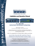
INC
®
Installation and Operation Manual
SS 4.1 III
Four Input, Single Output Stereo Switcher/Router
Manual Update: 02/13/07
Due to the dynamic nature of product design, the information contained in this
document is subject to change without notice. Broadcast Tools, Inc., assumes no
responsibility for errors and/or omissions contained in this document. Revisions
of this information or new editions may be issued to incorporate such changes.
Broadcast Tools® is a registered trademark of Broadcast Tools, Inc.
Copyright„ 1989 - 2007 by Broadcast Tools, Inc. All rights reserved.
No part of this document may be reproduced or distributed without permission.
Visit www.broadcasttools.com for important product update information.
SS 4x1 III Installation and Operation Manual
Table of Contents
Section Title
Page #
Introduction . . . . . . . . . . . . . . . . . . . . . . . . . . . . . . . . . . . . . . . . . . . . . 3
Safety Information . . . . . . . . . . . . . . . . . . . . . . . . . . . . . . . . . . . . . . . . 3
Who to Contact for Help . . . . . . . . . . . . . . . . . . . . . . . . . . . . . . . . . . . 3
Product Description . . . . . . . . . . . . . . . . . . . . . . . . . . . . . . . . . . . . . . . 4
Applications . . . . . . . . . . . . . . . . . . . . . . . . . . . . . . . . . . . . . . . . . . . . . 4
Front Panel Description . . . . . . . . . . . . . . . . . . . . . . . . . . . . . . . . . . . . 4
Rear Panel Description . . . . . . . . . . . . . . . . . . . . . . . . . . . . . . . . . . . . 5
Installation Guidelines . . . . . . . . . . . . . . . . . . . . . . . . . . . . . . . . . . . . . 6
Specifications . . . . . . . . . . . . . . . . . . . . . . . . . . . . . . . . . . . . . . . . . . . 10
Warranty . . . . . . . . . . . . . . . . . . . . . . . . . . . . . . . . . . . . . . . . . . . . . . . 11
CONTENTS
e-mail: [email protected] v o i c e : 360.854.9559 fax: 360.854.9479
2
SS 4x1 III Installation and Operation Manual
INTRODUCTION
Thank you for your purchase of a Broadcast Tools® SS 4.1 III, Four Input,
Single Output Stereo Switcher/Router (referred to as the SS 4.1 III throughout
this manual). We’re confident that this product will give you many years of
dependable service.
This manual is intended to give you all the information needed to install and
operate the Broadcast Tools® SS 4.1 III, Four Input, Single Output Stereo
Switcher/Router.
CAUTION!
Broadcast Tools®
Products, as with any
electronic device, can
fail without warning.
Do not use this product
in applications where a
life threatening condition
could result due to failure.
SAFETY INFORMATION
Only qualified personnel should install Broadcast Tools® products. Incorrect or
inappropriate use and/or installation could result in a hazardous condition.
WHO TO CONTACT FOR HELP
NOTE:
This manual should be
read thoroughly before
installation and operation.
If you have any questions regarding your product or you need assistance, please contact your distributor from whom you purchased this equipment.
If you would like more information about Broadcast Tools® products, you may
reach us at:
Broadcast Tools, Inc.
131 State Street
Sedro-Woolley, WA 98284-1540 USA
Voice: 360 . 854 . 9559
Fax: 360 . 854 . 9479
Internet Home Page: www.broadcasttools.com
E-mail:
[email protected]
WEBSITE:
Visit our web site for
product updates and
additional information
THANK YOU FOR CHOOSING
BROADCAST TOOLS® BRAND PRODUCTS!
INTRODUCTION
e-mail: [email protected] v o i c e : 360.854.9559 fax: 360.854.9479
3
SS 4x1 III Installation and Operation Manual
PRODUCT DESCRIPTION
The SS 4.1 III passively switches or routes a variety of electrical signals to a destination. The SS 4.1 III selects any one of 4 stereo inputs to a single stereo output.
The SS 4.1 III provides PASSIVE switching through gold contact relays. The passive
switching means that the unit can route a signal in both directions (any one of 4
stereo inputs to a single destination, or a single source to any one of 4 destinations).
Due to the passive nature of the switching, any input level and impedance can be
used. Inputs may be balanced or unbalanced, while output levels, impedance, distortion, noise and balancing will match that of the selected input. In addition to their
normal use with audio signals, the unit can also be used to switch digital signals and
telephone lines.
The SS 4.1 III is controlled by means of front panel switches, contact closures, 5-volt
TTL/CMOS logic levels and/or a multi-drop serial port.
The SS 4.1 III has several unique features. The Power-Up feature allows the user to
select which of any source is active at power up, including the last source selected.
Audio mute allows the user to turn off the audio output when activated. A Step Input
provides a means of stepping though each source, including MOH Station Selection. A
Serial Port allows communication and operation from a computer’s serial port. Source
number one is configured by default to route audio to the output in the case of loss of
power to the unit. Non-selected sources are terminated with 10K W, load resistors.
APPLICATIONS
Some of the applications of the SS 4.1 III; Studio selection and routing; Audio processing select; Exciter input select; Remote broadcast input selection; STL source
selection; Automation source selection; Multiple station Music On-Hold and/or PA
switching; EAS audio switching; ISDN or Phone hybrid feed selection; IFB selection;
Satellite audio channel switching and console monitor inputs and outputs selection.
FRONT PANEL DESCRIPTION
Source Switches:
Each switch represents an input to be routed to the switcher’s output. High quality tactile switches will give the user years of dependable service. Each switch has an associated LED indicator, which will illuminate when that particular source is routed to the
output. When a source is selected, the previous source will be deselected, (interlocked). The front panel is also equipped with a MUTE switch. This switch turns off
the audio output.
LEDs:
LED indicators will illuminate when the desired channel is selected. The Pwr/Ser
LED displays valid power and serial data activity. The mute LED denotes when
audio is off.
DESCRIPTION
e-mail: [email protected] v o i c e : 360.854.9559 fax: 360.854.9479
4
SS 4x1 III Installation and Operation Manual
REAR PANEL DESCRIPTION
The rear panel contains the inputs, outputs and remote control interfacing connectors. Audio inputs, outputs and remote control connections are pluggable screw terminals. A RJ-11 modular jack is provided for the multi-drop serial port.
Power:
Connect the 2.1mm coaxial type power connector into the unit and the 9 VAC @ 1
amp wall transformer into a 120 Vac 50-60 Hz power source. The front panel
Pwr/Ser LED indicates when power is applied to the unit. (CE 220 Vac 50-60 Hz
wall transformer OPTIONAL)
Audio Signal Connector:
The SS 4.1 III is supplied with Pluggable Screw terminals (Euro) and Mating connectors. Channel and polarity designators can be found on the chassis, as viewed
from the rear.
“Remote” Control Connector:
Pluggable Screw terminals (Euro) and mating connectors are provided for connection to equipment, which will remotely control the SS 4.1 III. Pulsing the “MUTE”
input to ground (low) would turn off the output of the SS 4.1 III until a front panel
source switch is pressed, a remote control input is activated or the unit is powered
up. Pulsing the “STEP” input to ground will step the unit one source for each low
to high transition on this input. Automatic sequence may be accomplished by holding the step input low for two seconds. The unit will now step to each source every
50 seconds. The step input is helpful in freeing up valuable remote control channels.
This feature may also be used to sequence through multiple station air monitor signals for program on-hold feed.
WEBSITE:
Visit our web site for
product updates and
additional information
DESCRIPTION
e-mail: [email protected] v o i c e : 360.854.9559 fax: 360.854.9479
5
SS 4x1 III Installation and Operation Manual
INSTALLATION GUIDELINES
It is recommended that all cables connected to the SS 4.1 III be looped through ferrite cores to suppress RF. Surge protection with RF filtering such as the Tripp Lite
“ISOBAR 4” is also suggested for the power transformer. The purchase of an inexpensive uninterruptible power supply (UPS) will provide back up in case of power
outages.
The SS 4.1 III is simple to install. Connections are via pluggable screw terminals.
Installation of the SS 4.1 III consists of seven steps:
1.
2.
3.
4.
5.
6.
7.
Inspection
Removal of the source termination resistors, if applicable
Bench test and option set-up
Mount the unit in a rack (RA-1), desktop or wall
Connect your equipment to the unit
Label the front panel switches
Serial operation, if applicable
STEP 1: INSPECTION
Please examine your SS 4.1 III carefully for any damage that may have been sustained during shipping. If any is noted, please notify the shipper immediately.
Retain the packaging for inspection by the shipper. The package should contain the
SS 4.1 III, this manual, 9 VAC @ 1 amp transformer, reversed modular cable, 9-pin
(S9) D-Sub adapter and audio and remote control mating connectors.
STEP 2: SOURCE TERMINATION RESISTOR REMOVAL
Input sources that are not selected are terminated with a 10K W. If you do not want
this load applied across the deselected sources, it may be removed from each channel. Each channel has a pair of resistors.
EXAMPLE: Channel 1, relays K1 A&B switches the signal; R15 & R21 are the
load resistors. As delivered, all channels are configured with these resistors
installed. To remove the load resistors from a channel, locate via the schematic the
proper resistors for that channel, cut its leads and discard the resistors.
CAUTION!
Installation of the SS
4.1 III in high RF environments should be
performed with care.
Shielded cable is suggested for all control,
audio inputs and outputs. All shields should
be tied to the “CH
GND” terminal on
each channel. The station ground should be
connected to the chassis ground screw (CH1)
located behind J1 as
viewed from the rear.
For lightning protection, check out
www.polyphaser.com
and www.itwlinx.com.
WEBSITE:
Visit our web site for
product updates and
additional information
STEP 3: BENCH TEST and OPTIONS
Place each unit on a workspace and connect power to the unit. Check to see if LED
#1 (Switch 1) and the Pwr/Ser LED are lit (Source one is the power-up factory
default). Connect an audio source to stereo input one and a monitoring device to the
output. Verify that audio is present. Repeat the process until each channel’s operation has been verified.
INSTALLATION
e-mail: [email protected] v o i c e : 360.854.9559 fax: 360.854.9479
6
SS 4x1 III Installation and Operation Manual
DIP (SW - 6) Switch Functions
Unit ID SW6-1
SW6-2
ID 0 *
OFF
OFF
ID 1
ON
OFF
ID 2
OFF
ON
ID 3
ON
ON
Baud Rate SW6-3
2400
ON
9600 * OFF
19200
OFF
38400
ON
* = Factory setting
SW6-4
OFF
OFF
ON
ON
SW6-5
OFF = Last source selected *
ON = Power up selection
SW6-6
OFF = Normal operation *
ON = Act as a SS 2.1 switcher/Router
Input selection at power-up may be determined by holding down the desired channels push button until all LED’s flash. Factory power-up default is source # 1.
STEP 4: MOUNTING
Mount the unit in a rack or desktop, allowing adequate airflow for cooling.
STEP 5: CONNECT YOUR EQUIPMENT
The SS 4.1 III interfaces to your equipment (sources and loads) through the rear
panel pluggable screw terminals. Follow the legends for the desired audio input,
output and remote control connections, which appear on the rear side of the chassis.
Remove each screw terminal, strip each conductor, and insert the conductor into the
terminal and screw down the capture screw. The terminals accommodate wire sizes
from 16 - 28 AWG solid or stranded wire.
STEP 6: LABEL SWITCHES
Write the source descriptions under each source switch, if desired.
INSTALLATION
e-mail: [email protected] v o i c e : 360.854.9559 fax: 360.854.9479
7
SS 4x1 III Installation and Operation Manual
STEP 7: SERIAL OPERATION
The supplied reversed modular cable and 9-pin (S9) D-sub adapters may be connected to the SS 4.1 III’s rear panel modular connector. Plug in the D-sub adapter
into your computer’s serial port. Plug the supplied wall transformer into a source of
117 vac and the cable end of the transformer into the power receptacle on the SS 4.1
III. The protocol is as follows: 2400, 9600, 19200, 38400, 8N1. Flow control
should be set to NONE, emulation to ANSI and the mode should be set to DIRECT
TO COMx (x = the available com port). The default is 9600, 8,N,1.
Commands:
The start of string character may be either a * (asterisk) or _ (underscore) character.
The second character of the string is the unit (u) number, 0 to 3.
The third character is the input (i) number, 1 thru 4 or M.
The third character may also be used to save a power up channel when SW6-5 is ON.
*ui
_ui
i = input 1 thru 4 or M to mute the output
i = Input 1 thru 4 or M to mute the output
*uS
_uS
Save current input on power up
Save current input on power up.
Examples:*04
This string would turn on channel 4 on unit 0
_04
This string would turn on channel 4 on unit 0
STEP 7: SERIAL OPERATION Continued
Serial: Pin out of the RJ-11 modular/(S9) D-Sub adapter is shown below.
RJ-11
Adapter.
Pin Number.
4
DB-9 Female. Pin
Number.
3
Product’s point of
view Function
Name.
RS-232 Receive
3
2
RS-232 Transmit
2
5
Ground
WEBSITE:
Visit our web site for
product updates and
additional information
Modular connectors point of view.
INSTALLATION
e-mail: [email protected] v o i c e : 360.854.9559 fax: 360.854.9479
8
SS 4x1 III Installation and Operation Manual
Remote Control Connector:
The front panel functions are brought out through the rear panel “REMOTE” connector TB 4, providing a means of controlling the SS 4.1 III from a remote point.
The digital inputs may be connected to any remote pair of switch contacts, such as
external relays, switches, open-collectors or 5-volt logic signals.
Status:
The status signals are supplied through the “Remote” control connector as individual open collectors. The open collectors may be used to provide status to a remote
control point to indicate which source is selected. The status output for the selected output will go low, providing a return for an LED indicator, TTL/CMOS logic
or relay. External pull-up resistors may be required in some installations.
Rear Panel Connectors
TB 1 --> TB 2
Input x – Left
Input x – Left
TB 3
Output – Left
TB 4
Open
Collector 1
Input 1
EVEN Inputs
Top Row
Chs
Input x – Right Input x + Right
Gnd
Input x + Left
Chs
Input x – Right Input x + Right
Gnd
ODD Inputs
Bottom Row
Input x + Left
Output + Left
Output
Chs
Gnd
Top Row
Output – Right Output + Right
Open Collector Outputs Top Row
Open
Open
Open
Ground
Collector 2 Collector 3 Collector 4
Input 2
Input 3
Input 4
Mute
Remote input selection Bottom Row
Ground
Step
INSTALLATION
e-mail: [email protected] v o i c e : 360.854.9559 fax: 360.854.9479
9
SS 4x1 III Installation and Operation Manual
SPECIFICATIONS
Inputs/Outputs:
Any input level and impedance can be used. Inputs
may be balanced or unbalanced. Output levels,
impedance, distortion, noise and balancing will match
that of the selected input.
Switching Method:
Passive. Sealed relays utilizing 2-form-C bifurcatedcrossbar silver alloy with gold overlay contacts
Logic:
Flash microprocessor, non-volatile memory
Operation Control:
Front Panel - Momentary switches.
Remote - Momentary closure to ground or 5 Volt
TTL/CMOS Logic levels.
Serial - RS-232c, 6P4C reversed modular cable with
9- pin (S9) D-Sub adapter, 2400, 9600, 19200, 38400
/ 8,N,1
Status:
Front Panel - Indicator LED.
Remote - Open collector outputs, 12 vdc, limit current
to 50ma per output. Pull-ups may be required.
Interfacing:
Audio& Remote Control - Pluggable screw terminals
(Euro).
RS-232 - 4C6P Modular. All mating connectors,
reversed modular cable and (S9) adapter supplied.
Power Requirements:
9 Vac, 1 amp. 120 Vac 50-60 hz transformer. (CE 240
Vac 50-60 Hz optional)
Physical Dimensions:
5.50” x 6.50” x 1.55” (WDH)
Weight:
2.0 lb.
WEBSITE:
Visit our web site for
product updates and
additional information
SPECIFICATIONS
e-mail: [email protected] v o i c e : 360.854.9559 fax: 360.854.9479
10
SS 4x1 III Installation and Operation Manual
LIMITED WARRANTY
The term “Buyer” as used in this document refers to and includes both (but only) (a) any person or entity who acquires such an item for
the purpose of resale to others (i.e., a dealer or distributor of an item), and (b) the first person or entity who acquires such an item for
such person’s or entity’s own use.
Broadcast Tools warrants to each Buyer of any item manufactured by Broadcast Tools that the item will be free from defects in materials and workmanship at the time it is shipped by Broadcast Tools if the item is properly installed, used and maintained.
EXCLUSIVE REMEDIES
If Broadcast Tools is notified, in writing, of a failure of any item manufactured by Broadcast Tools to conform to the foregoing Limited
Warranty within one (1) year following the date of the Buyer’s acquisition of the item, and if the item is returned in to Broadcast Tools in
accordance with Broadcast Tools’ instructions for confirmation by inspection of the defect (which at Broadcast Tools’ election may
include, without limitation, a requirement that the Buyer first obtain a Return Authorization number from Broadcast Tools, that the Buyer
furnish proof of purchase in the form of an invoice and/or receipt, and that the Buyer prepay all freight charges associated with any return
of the item to Broadcast Tools using such freight service as Broadcast Tools reasonably may specify), Broadcast Tools will repair or
replace the defective item, or will refund the purchase price paid by the Buyer for the item. Broadcast Tools shall have the exclusive
right to choose between these alternative remedies.
NO OTHER WARRANTIES OR REMEDIES
TO THE MAXIMUM EXTENT PERMITTED BY APPLICABLE LAW, BROADCAST TOOLS AND ITS SUPPLIERS DISCLAIM ALL OTHER
WARRANTIES, EITHER EXPRESS OR IMPLIED, INCLUDING BUT NOT LIMITED TO IMPLIED WARRANTIES OF MERCHANTABILITY OR FITNESS FOR A PARTICULAR PURPOSE; AND THE FOREGOING ALTERNATIVE REMEDIES SHALL BE EXCLUSIVE OF
ALL OTHER REMEDIES. THIS LIMITED WARRANTY GIVES YOU SPECIFIC LEGAL RIGHTS. YOU MAY HAVE OTHER RIGHTS,
WHICH VARY FROM STATE/JURISDICTION TO STATE/JURISDICTION.
N O L I A B I L I T Y FOR CONSEQUENTIAL D A M A G E S
TO THE MAXIMUM EXTENT PERMITTED BY APPLICABLE LAW, NEITHER BROADCAST TOOLS NOR ANY OF ITS SUPPLIERS
SHALL HAVE ANY LIABILITY FOR ANY SPECIAL, INCIDENTAL, INDIRECT, CONSEQUENTIAL OR PUNITIVE DAMAGES WHATSOEVER (INCLUDING, WITHOUT LIMITATION, ANY DAMAGES FOR LOST PROFITS, BUSINESS INTERRUPTION, LOSS OF DATA OR
INFORMATION, COST OF CAPITAL, CLAIMS OF CUSTOMERS, OR ANY OTHER PECUNIARY LOSS) ARISING OUT OF THE USE
OF OR THE INABILITY TO USE ANY ITEM SUPPLIED BY BROADCAST TOOLS), EVEN IF BROADCAST TOOLS HAS BEEN
ADVISED OF THE POSSIBILITY OF SUCH DAMAGES HAVE ANY LIABILITY FOR ANY SPECIAL, INCIDENTAL, CONSEQUENTIAL,
EXEMPLARY OR PUNITIVE DAMAGES. THIS LIMITATION OF LIABILITY APPLIES WHETHER A CLAIM IS ONE ALLEGING
BREACH OF A CONTRACT OR WARRANTY, NEGLIGENCE OR OTHER TORT, FOR THE VIOLATION OF ANY STATUTORY DUTY,
THE FAILURE OF ANY LIMITED OR EXCLUSIVE REMEDY TO ACHIEVE ITS ESSENTIAL PURPOSE, OR ANY OTHER CLAIM OF
ANY NATURE. BECAUSE SOME STATES AND JURISDICTIONS DO NOT ALLOW THE EXCLUSION OR LIMITATION OF LIABILITY
FOR INCIDENTAL OR CONSEQUENTIAL DAMAGES, THIS LIMITATION MAY NOT APPLY TO YOU.
Broadcast Tools, Inc.
131 State Street
Sedro-Woolley, WA 98284 • USA
360.854.9559 voice • 360.854.9479 fax
[email protected] e-mail
www.broadcasttools.com website
LIMITED WARRANTY
e-mail: [email protected] v o i c e : 360.854.9559 fax: 360.854.9479
11