1
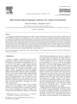
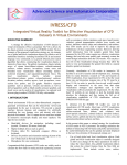
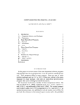
Advances in Engineering Software 32 (2001) 295±315 www.elsevier.com/locate/advengsoft Object-oriented virtual environment for visualization of ¯exible multibody systems T.M. Wasfy, A.K. Noor* Center for Advanced Computational Technology, Mail Stop 201, NASA Langley Research Center, University of Virginia, Hampton, VA 23681, USA Accepted 4 August 2000 Abstract An object-oriented event-driven virtual environment (VE) for viewing the simulation results of ¯exible multibody systems (FMS) is developed. The VE interfaces with the following output devices: immersive stereoscopic screen(s) and stereo speakers; and a variety of input devices including, head tracker, wand, joystick, mouse, microphone, and keyboard. The VE incorporates the following types of primitive software objects: user-interface objects, support objects, geometric entities, and ®nite elements. Each object encapsulates a set of properties, methods, and events that de®ne its behavior, appearance, and functions. A ªcontainerº object allows grouping many objects into one object, which inherits the properties of its ªchildrenº objects. The VE allows real-time viewing and ª¯y-throughº of photo-realistic models, vibrational mode-shapes, and animation of the dynamic motion of FMS. An application of this VE is presented for visualization of the dynamic analysis results of a large deployable space structure Ð NASA's Next Generation Space Telescope. Published by Elsevier Science Ltd. Keywords: Virtual environment; Flexible multibody systems; Finite elements 1. Introduction 1.2. Major components of a virtual environment 1.1. De®nition of a virtual environment In order for a VE to mimic the real environment it must be able to couple the sensory output of the environment to the real-time actions (navigation) of the user(s). Recent review articles [2,3] and a book [4] provide an overview of the current research on coupling the visual output (for recognition, tracking of moving objects, distance judging, search, and size estimation), auditory output (for recognition and sound localization), and kinesthetic/haptic output, with the user's navigation (¯y-through and manipulation of objects) in the VE. The studies reviewed conclude that, in order to achieve a ªrealisticº VE (a VE in which the user is fully immersed and feels as if he/she is actually ªpresentº), the following capabilities are needed: Virtual or synthetic environments (VEs) are three-dimensional, computer generated environments that occur in realtime as manipulated by the user [1]. A VE is a projection of either some real environment, a fairly realistic environment that does not exist, or an unreal environment (e.g. for entertainment and games). VEs provide a natural interface between humans and computers by arti®cially mimicking the way humans interact with their physical environment. A VE includes facilities for interfacing with humans through output of sensory information and input of commands. Output facilities include an immersive stereoscopic display and stereo sound. Input facilities include a hand-held 3D navigation device such as a wand, joystick, or 3D mouse; a 2D navigation device such as a mouse or a touch pad; a haptic feedback device such as gloves; devices for position and orientation tracking of parts of the user's body (such as the head and hands); a microphone for voice commands; and a keyboard. * Corresponding author. Tel.: 11-757-864-1978; fax: 11-757-864-8089. E-mail address: [email protected] (A.K. Noor). 0965-9978/01/$ - see front matter. Published by Elsevier Science Ltd. PII: S 0965-997 8(00)00091-0 ² high-resolution (minimum 1280 £ 1028 24-bit color, ¯icker and ghosting free, stereoscopic display; ² frame rate of at least 15 frames/s; ² head tracking; ² large ®eld-of-view (FOV) . 408; ² light source based-rendering; ² photo-realistic textures; ² consistency (the object's position and appearance are predictable, as like in a real environment); ² no disturbance from the real-world environment; 296 T.M. Wasfy, A.K. Noor / Advances in Engineering Software 32 (2001) 295±315 ² navigation tool that allows accurate direction pointing and ¯y-through or walk-through in the environment. In addition, the following capabilities are not essential, but can enhance the realism of the VE: ² Recognizing the actions of the user such as touching or clicking an object. Many VEs have included standard graphical user interface objects such as buttons, dials, menus, and checkboxes [3]. ² Generating secondary motion effects where a user's motion and actions in the VE generate motion of other objects in the environment. This also includes computational steering, where the user can change the parameters of the model in the VE and watch the simulation respond to that change [5,2,6]. In Ref. [7] lumped masses, springs, a simpli®ed ¯uid dynamics model, and collision detection were used to model leaves, clothing, a ¯exible ¯oor mat, and stepping in a puddle. In that reference two-way, one-way, and hybrid coupling were used between the primary motion and the secondary motion objects. As expected, two-way coupling requires much more computational power than the one-way or hybrid coupling approaches. For practical real-life systems computational steering was only achieved when the model was grossly simpli®ed. For example, in Ref. [8] a virtual molecular simulation system with computational steering was developed. Real-time simulation was obtained for a model of up to 450 atoms. They conclude that a massively parallel computer is required for the simulation of 10,000 atoms. Today's computers do not have enough speed to simulate, in real-time, the dynamics of 10 4 ±10 7 DOF systems, which is the size of practical models. ² Stereo realistic sound effects which can help the user localize the sound producing objects. ² Two way natural language communication, including voice commands. The VE can feature an intelligent, voice-enabled virtual assistant, which can respond to the user's speech [9]. ² Support for haptic feedback devices such as gloves and a pressure sensitive joystick with force feedback. ² Tracking multiple points on the user's body. This allows the user to use multiple parts of his body (e.g. hands, head, and legs) to interact with the VE. It also allows displaying realistic ªavatarº for the user, which closely mimics the user's actual movement. 1.3. Brief review of previous VE applications and studies Several applications of VEs have been reported in the literature in engineering, medicine, and entertainment. In engineering, VEs have been used for: ² Visualization of 3D models of engineering systems (e.g. geographic information systems for agriculture, geology, ² ² ² ² ² ² ² ² urban planning, and telecommunications [10,11]; architectural visualization and walkthrough [12]). Visualization of numerical and experimental simulation results (e.g. automotive crash visualization [13,14]; ¯uid ¯ow visualization for automotive and aerospace applications [15±17]). Computational steering and simulation-based design (e.g. molecular simulation for material characterization [8]; visualization and computational steering for a tractor lift arm [5]; landing gear modeling [4]). Solid modeling [19±21]. Virtual product development including design and virtual prototyping (e.g. automotive assembly and design [4]; robotics modeling and design [20]). Virtual manufacturing and factory simulation [4]. Tele-collaboration. Tele-presence [18]. Training and education [22]. Most of the aforementioned VE studies use an objectoriented approach to represent the various virtual objects, which simulate the behavior of the real objects. In an objectoriented paradigm, each object ªencapsulatesº a set of properties (data), which determines its appearance and behavior. The objects are polymorphic, which means that objects of different types can contain or respond to the same function without regard to the object type. The objects are persistent, which means that they behave in a natural predictable way. Also, their properties can be modi®ed, they can be deleted, and new objects can be added. In addition, different objects can be grouped together into one ªgroup objectº. The last characteristic allows a hierarchical, directed, tree-type representation of the VE. The group object can be transformed (translated, rotated, and scaled) as one entity. This hierarchical object-oriented representation (including the transformation hierarchy) is called the ªscene graphº [23]. Several general-purpose toolkits, based on the scene-graph approach [24], have been developed for construction and display of VEs. Among the toolkits that enable the development of custom VE applications are: SGI's Inventor [25], SGI's IRIS Performer 2.0 [26], WorldToolKit (WKT) from Sense8 [27], MR Toolkit [28], muse SDK [29], Karma VI [11] for GIS visualization, and Lego Toolkit [30]. These toolkits consist of a collection of C/C11 functions and classes for interfacing with the various hardware components and navigation in the VE. The Virtual Reality Modeling Language 2.0 (VRML 2.0) [31] is a ®le format speci®cation for scene-graph description of VEs on the internet. VRML includes a set of primitive geometry, grouping, sensor, interpolator, texture map, and lights objects that allow construction of dynamic interactive multimedia VEs. 1.4. Application of VEs to ¯exible multibody systems A ¯exible multibody system (FMS) is a group of interconnected rigid and deformable solid bodies (or T.M. Wasfy, A.K. Noor / Advances in Engineering Software 32 (2001) 295±315 297 LCD Shuttered Glasses with Stereo Receiver Output Devices Speakers Support Computer Ethernet Port Microphone Stereoscopic Display Stereo Emitter Display Computer Ethernet Port Keyboard Input Devices Support Computer Ethernet Port Mouse / Touch Pad Head Tracking Receiver Wand Gloves Wand Tracking Receiver Tracking Emitters Fig. 1. Schematic diagram of the VR system hardware. components), each of which may undergo large 3D motions. Typical connections between the components include: revolute, spherical, prismatic, and planar joints, gears, and cams. The bodies can be connected in closedloop con®gurations (e.g. linkages) and/or open-loop (or tree) con®gurations (e.g. manipulators). A large number of practical devices and systems can be modeled as an FMS. These include: ground, air, and space transportation vehicles (automobiles, trains, airplanes, and spacecraft); manufacturing equipment; machines; manipulators and robots; mechanisms; articulated earth-bound structures (such as cranes and draw bridges); articulated space structures (such as deployable satellites, space telescopes, and space stations); microelectro-mechanical systems (MEMS), and bio-dynamical systems (human body and animals). Physics-based techniques for modeling the dynamics of FMS generate the time histories of quantities of interest in design and control of these systems such as motion, strain, stress, and internal forces. In addition, the models can also generate the frequency response of the FMS including mode shapes and natural frequencies. The majority of high-®delity physics-based models of large FMS are based on the ®nite element method. Solid shell, beam, and truss elements are used to model the various ¯exible components. FMSs naturally lend themselves to the objectoriented as well as the scene-graph representation [32,20]. VEs can be used to visualize geometric and ®nite element models of FMS as well as dynamic simulations of the motion of the FMS calculated using physics-based simulation codes. Users can move around the model of the FMS while it is moving, and look at it from any position or angle. The ªclose to real-lifeº visualization allowed by the VE helps to quickly attain a better understanding of the FMS and its dynamic response. Typical ways of displaying an FMS in a VE include any combination of the following: ² photo-realistic rendering of the FMS in its ®nal environment; ² ®nite element mesh of the FMS with exploded elements and/or element boundaries; ² animation of the motion of the FMS; ² shading of the FMS using a scalar response quantity such as a stress/strain component, strain energy density, and displacement component, etc.; ² animated mode shapes; ² 2D or 3D graphs of time histories of response quantities of interest. A user interface inside the VE allows the user to control the way the model is displayed. Typical user actions include controlling the animation speed, setting shading parameters and selecting the shading variable, loading a model, moving objects (e.g. light sources and model parts), selecting natural frequencies and mode shapes, selecting graph variables, etc. 1.5. Objectives and scope of the present study The objective of the present study is to describe an objectoriented, scene-graph toolkit Ð IVRESS (Integrated Virtual-Reality Environment for Synthesis and Simulation) Ð which is speci®cally designed for visualization of FMS ®nite element simulation results. The Cave Automatic Virtual Environment (CAVE) facility at NASA Langley Research Center is used for demonstrating the effectiveness of this toolkit. IVRESS can be used to construct a ªrealisticº VE which supports the aforementioned ways of viewing FMS and their simulation results. Unlike other VE development toolkits that consist of a set of C/C11 298 T.M. Wasfy, A.K. Noor / Advances in Engineering Software 32 (2001) 295±315 with other computers. Fig. 1 shows a schematic diagram of the hardware con®guration of a typical VR facility that was used in conjunction with IVRESS. A typical VR facility, the CAVE, is shown in Fig. 2. The following output facilities were used: Fig. 2. CAVE facility. functions and classes, IVRESS is a stand-alone program. An object-oriented scripting language, IVRESS script, allows describing the various objects and writing custom event handling routines. Custom objects can be added to IVRESS by writing C/C11 code for the object and linking that code to IVRESS either dynamically (using a dynamic link library), or statically (by linking with IVRESS object ®les). Four types of ªmodularº objects are used to de®ne the FMS components, the data used for displaying the deformation, motion, and mode shapes of the FMS, as well as the user interface. These are: user-interface (UI) objects, support objects, geometric entities, and ®nite elements. Each object has a set of properties and methods that determine its appearance, behavior, and actions. Also associated with each object is a set of ªeventsº that are triggered when certain conditions, initiated by the user or the passage of time, are met. UI objects provide the functionality in the VE. Typical UI objects include buttons, check boxes, slider bars, text boxes, labels, graphs, tables, light sources, and selection tools. The scene-graph capability is enabled by using the ªcontainerº object, which is a special type of UI object that can contain ªchildrenº objects. Children objects are displayed using the homogeneous geometric transformation of the ªparentº container. Children objects can be other UI objects (including other containers), geometric entities, and ®nite elements. Support objects contain information that can be referenced by other objects. Typical support objects include material properties, time-history data, and mode-shape data. Geometric entities represent the geometry of the physical components of the FMS. Finite elements represent the numerical model of the physical components of the FMS. 2. Hardware of the virtual-reality facilities A review of the input (navigation) and output (display) devices of virtual-reality (VR) systems is presented in Ref. [2]. A VR system includes output and input facilities for interfacing with users, computers for generating the VE, and facilities for communication ² Immersive stereoscopic displays. Stereoscopic viewing is achieved by displaying the correct perspective view of the model for both eyes of the user. This can be achieved by using LCD shuttered glasses which are synchronized with the screen refresh rate. When the correct perspective view for the right eye is displayed, the left eye is blackened, and vice versa. An infrared emitter, which is linked to the display output signal, sends the screen refresh trigger signal to infrared receivers in the glasses to shutter them. A refresh rate above 72 Hz. (usually 96 Hz.) will result in a ¯icker free stereoscopic display. This technique is used in the CAVE and ImmersaDesk. Stereoscopic display can also be achieved by using head-mounted displays. These consist of two small LCD screens which display the correct perspective view for each eye. In order to achieve a high level of immersion, one or more large ¯at or curved screens, which allow an FOV larger than 458, are used. For example, in the CAVE, four ¯at 3 £ 3 m2 screens arranged as a cubical room (one front screen, two side screens, and a ¯oor or a ceiling screen) are used (FOV , 90±1808). In the ImmersaDesk, one ¯at 2 m screen is used (FOV , 458), and in the VisionDome one hemispherical 5±10 m diameter screen is used (FOV , 90±1808). ² Two or four speakers. The speakers can be used to output spoken messages, sound effects, and data soni®cation. The following input facilities were used: ² A position and orientation tracking device for tracking the position and orientation of the user. This can be achieved by using six or more ®xed electromagnetic or ultrasonic emitters and a receiver placed on the part of body to be tracked. The data from the receiver indicates the distance between the receiver and each emitter which is triangulated to obtain three position coordinates and three orientation angles of the receiver. Tracking receivers are usually placed on the stereo glasses for head tracking in order to calculate the correct perspective view, as well as a hand-held ªwandº for navigating and pointing in the VE. ² Tracked 3D navigation and selection device such as the wand. The wand has a pressure sensitive 2D joystick that can be used to control the speed and direction of motion. Also, the wand has two or more buttons that can be programmed to perform special functions. ² 2D navigation device such as a mouse, touch pad, or joystick. ² Microphone for voice commands. ² Keyboard. T.M. Wasfy, A.K. Noor / Advances in Engineering Software 32 (2001) 295±315 User Interface Objects 299 Support Objects Geometric Entities Finite Elements Container Nodal Coordinates Boundary Rep. Solid Observer Virtual Material Box, Cone, Sphere. Truss, Beam, Shell, Solid 3-D Selection Physical Property Surface 2-D Selection (Pointer) Physical Material Line, Poly-line Picture Buffer Arc, Circle Color Key Data Point Light Graphical Objects FE Data Button Check Box Controllers/Actuators Joints Hinge Joint Prismatic Joint Prescribed Motion Constraints Variable Font Label Text Box 2-D Graph 3-D Graph Picture Dial Table Color Key Fig. 3. The four types of objects. Typically, three computers are used: a display computer, a support computer for sound input/output, and a support computer for tracking and navigation (Fig. 1). The display computer is either an SGI Onyx station with an In®nite Reality 3 multi-pipe rendering engine or a Pentium III PC with an open-GL accelerated graphics card. The sound support computer is a Pentium III PC with a stereo digital sound card. The tracking and navigation support computer is also a Pentium III PC with interface boards for the tracking system and optional haptic-feedback gloves. Communication between the three computers is achieved by using a standard Ethernet connection. 3. Features of the object-oriented VE Fig. 3 shows the objects that can be used in the VE. These can be divided into four categories: UI objects, support objects, geometric entities, and ®nite elements (see Tables 1±4 for descriptions of the various available objects), and are described subsequently: ² UI objects (Table 1) provide various functions in the VE. Typical UI objects include container, button, check box, dial, and graph. The container is a special type of object that is used to group ªchildrenº objects. Typical uses of these objects include displaying information to the user in the VE as well as allowing the user to input data or commands in the VE. ² Support objects (Table 2) contain data that can be referenced by other objects. For example, a ®nite element refers to a nodal positions list, a physical material, and a material color support object. Operations such as arithmetic (addition, multiplication, and division) and logical (and, or, not,¼), can be performed on support objects. ² Geometric entities (Table 3) represent the geometry of the physical components of the multibody system. Typical geometric entities include boundary-representation solid, box, cone, and sphere. ² Finite elements (Table 4) represent the numerical model of the physical components of the multibody system. Typical ®nite elements include beam, shell, and solid elements. In addition, the scripting language, ªIVRESS-scriptº, can be used to customize the VE for the multibody system application. An IVRESS script ®le consists of subroutines and objects. Each subroutine has a name, a list of input/output parameters, and a main body of script commands. The script is interpreted and executed one command at a time. All objects have the same basic structure. Each object de®ned in the script ®le has a name and may be followed by a list of properties and property values. Property values that are not explicitly de®ned are set to a default value. Also, each object is automatically assigned a unique reference number. The object can be referenced either by its name or reference number. Each object has properties that 300 T.M. Wasfy, A.K. Noor / Advances in Engineering Software 32 (2001) 295±315 Table 1 UI objects Table 1 (continued) UI object Description Container The container is a special type of UI object that is used to group ªchildrenº objects. Children objects are displayed using the homogeneous 4 £ 4 geometric transformation matrix of the ªparentº container. Other UI objects (including other containers, geometric entities, and ®nite elements can be children objects. Each multibody system component is represented by a container that holds geometric entities for representing the geometry of the component and ®nite elements for representing the numerical model of the component. A ªshapeº property for the container determines its shape appearance. It can be set to 2D form, box, room, or noshape. Observer The observer is used to de®ne the viewer's head position and orientation. The observer object is controlled by using the wand. The user points the wand in the direction he wants to move, then uses the pressure sensitive joystick to control the speed of motion in that direction. Also, by holding a function key on the wand and using the pressure sensitive joystick, the user can rotate around the axis of the wand. 3D selection tool The 3D selection tool is used to select, move, and touch objects in the VE. The 3D selection tool is controlled using the wand. The object consists of a selection bounding box and two perpendicular vectors, indicating the current spatial orientation of the wand. The user points the wand in the direction he wants the selection box to move (the direction vector) and then uses the pressure sensitive joystick to control the speed of motion in that direction. Once the selection bounding box touches an object, a touch event for that object is triggered which, in turn, executes an associated subroutine. Also, a click event is triggered when the selection box is touching the object and the user clicks the ®rst wand function key. 2D selection tool Light Similar to the 3D selection tool, the 2D selection tool is used to select, move, touch, and click on objects. The 2D selection tool consists of a selection bounding box which can only move in a plane. The motion of the 2D selection tool can be controlled using the wand's joystick, a mouse, or a touch pad. Light sources can be de®ned in the VE. The properties of a light source include position, spot direction, spot angle, color, and intensity. Geometric entities and ®nite elements of the multibody system are rendered using the active light sources. UI object Description Button The button is used to perform prede®ned functions which are triggered by user generated events including clicking and touching the button using a 2D or 3D selection tool. The button changes its appearance when it is touched. The button appearance properties include color, shape, and texture picture. Check box The user toggles the check box on and off by clicking on it using a selection tool. Label The label displays single or multi-line text. Text box The text box displays single or multi-line editable text. 2D and 3D graphs The graph object displays static or animated time-dependent plots. The graph reads its data from a FE data support object. Picture Displays a single picture or multiple pictures (movies). The picture reads the image data from an image data support object. Standard image and movie formats are supported. Dial The dial points to a speci®ed dial position in a continuous range. The dial object can be used as a slider bar by dragging the dial pointer to change the position of the dial. Linear and rotary dials can be displayed. Table The table is a spreadsheet object used for displaying or editing text in a 2D tabular form. Color key The color key is a bar which displays the mapping between the value of a shading variable and the shading color. The color key data is read from a ªcolor key dataº support object. determine its state and behavior, methods which are functions that it can perform, and events that are triggered when certain conditions are met. Common properties of UI objects include translation, orientation, scale, foreground material color name, background material color name, and visibility. Common properties of geometric entities include names of the material color, physical material, and image texture support objects. Common properties of ®nite T.M. Wasfy, A.K. Noor / Advances in Engineering Software 32 (2001) 295±315 Table 2 Support objects Support object Description Geometric property This support object has the following properties: Shell thickness. Beam cross-sections and moments of inertia. Physical material This support object has the following properties: Material type (linear, isotropic, orthotropic, general,¼). Values for the material parameters: Young's modulus, Poisson ratio, density, thermal conductivity,¼. Material color Contains the color information which includes: ambient color, diffuse color, specular color and, shininess. Image Stores a single picture or a series of pictures (a movie). An image object has the following properties: Red, green, blue, and transparency intensities for each pixel. Horizontal and vertical pixel size of the image. Number of pictures (1 for a still image and .1 for a movie). Font Connectivity and control-point positions for each character. Nodal positions Stores a list of nodal positions. This support object has the following properties: The total number of nodes N. A list of 3 £ N ¯oating point values. Each three of these numbers correspond to the position coordinates of a node. FE data For storing ®nite element vectors such as nodal positions, velocities, and accelerations; nodal values (stress, strain, displacement,¼), element values (stress, strain¼), other response quantities of interest (relative angles, internal force and torque, controller actions,¼). It can store time-independent, time-dependent, or frequency dependent data. Variables This support object can store either single values or arrays of values. The data type for these variables include variant, string, integer, single-precision ¯oat, and real. Color key data Contains a list of colors and corresponding normalized values between 0 and 1, which are used for shading a model using a response variable. Texture map Contains texture parameters for mapping an image texture on a geometric entity. These include: name of the image support object, algorithm for wrapping the picture on the geometric entity, rotation, and repetition of the picture. elements include names of the physical material, material color, and nodal positions support objects, as well as the element nodal connectivity. Common methods of all objects include: Draw and Check-events. The container methods 301 invoke the methods of all the children nodes. For example, the container Draw method invokes all Draw methods of all the objects contained within, including other containers. Typical events include Touch, Press, and Click. For example, the Touch event is invoked when a selection tool touches the object. The Click event is invoked when a selection tool is touching the object and the user clicks on the ®rst wand button. An event is triggered by calling a subroutine associated with that event. The subroutine name consists of the object name concatenated with an underscore and the event name (e.g. object-name_event-name). IVRESS can read and write ®le formats for geometry data (e.g. VRML 2.0 [31], Open Inventor [25], DXF [33], and LightWave [34]), ®nite element information (e.g. MSC/ NASTRAN [35], MSC/DYTRAN [36], ABAQUS [37], and DIS [38]), pictures (e.g. Bitmaps, PNG, JPEG, and GIF), movies (e.g. MPEG and AVI), and user interfaces (e.g. VRML 2.0) ®les. In addition, IVRESS has facilities for voice commands and communication with other computers. A ¯ow chart of a typical execution sequence is shown in Fig. 4. When IVRESS is executed, an initial container called ªWorldº is created. Then a default script ®le is loaded. Inside the script ®le an entry-point command is used to de®ne the starting subroutine. The starting subroutine executes the following functions: ² ² ² ² ² ² ² open the raster display; set display parameters; load true-type fonts; load other included script ®les; place objects in appropriate containers; run the initialization subroutines; start the display loop. All root containers should be placed inside the ªWorldº container using the ªAddº container method. The Draw and Check-events methods for the ªWorldº container are called during the display loop at each frame update. These in turn call the Draw and Check-events methods for all objects inside ªWorld.º 4. Application of the VE to multibody systems After starting the VE, the user can load a multibody system simulation. A typical simulation script consists of six main steps. Step 1. Create a root container (for example, MBS) for the multibody system and place it in the World container. Step 2. Create UI objects such as graphs, dials, checkboxes, buttons, and containers (for organizing and grouping other UI objects) for displaying custom data for the multibody system. Those objects are also placed in MBS. 302 T.M. Wasfy, A.K. Noor / Advances in Engineering Software 32 (2001) 295±315 Table 3 Geometric entities Table 4 Finite elements Geometric entity Description Finite element Description Solids Box De®ned by its center point and three dimensions (width, length, and height). Solid (brick) Eight-noded solid brick element. Cone De®ned by its center point, top radius, bottom radius, and height. A cylinder is a special case of a cone with equal top and bottom radii. Shell (brick) Sphere De®ned by its center point and radius. Eight-noded shell element. The top shell surface is de®ned by the ®rst four nodes and the bottom surface by the last four nodes. The normal to the shell surface is the vector connecting the two surfaces. Truss Two-noded truss element. Beam Three-noded beam element. Zero-length spring Used to impose an equal position constraint on two nodes. It is used to de®ne hinge joints. Prismatic joint De®ned by two nodes which de®ne the path of the joint and a third node which is restricted to move on that path. Point mass De®ned by the value of the point mass at a node. Rotary actuator De®ned by the direction of the rotation axis, and three nodes corresponding to the actuator action points. Linear actuator De®ned using two nodes corresponding to the actuator action points. Indexed-face De®ned by a list of position coordinates and set connectivities. In addition, a list of normals and texture coordinates can also be speci®ed. These lists are stored as variables, arrays and supportobjects of an appropriate type and referenced by the indexed-face set using their names. If the indexed-face set forms a set of unintersecting closed surfaces, it represents a ªboundary-repº solid. Extrusion De®ned by using a closed curve for de®ning the cross-section and a path curve for de®ning the extrusion path of the cross-section. Surfaces Elevation surface De®ned by the length and width of the surface, the number of nodes along the length and width, and a list of elevation values. Curves Point Surface De®ned by a 2D ordered matrix of nodes. 3Dface De®ned by either three (triangle) or four (polygon) 3D points. Polyline An ordered list of 3D points that are connected by straight line segments to form the polyline. Line Two 3D points connected by a straight line segment. Spline An ordered list of 3D control points de®ne a Bezier spline. Circle De®ned by its center, radius, and a normal vector to the plane of the circle. Arc De®ned by its center, starting point, arc angle, and a normal vector to the plane of the arc. Ellipse De®ned by its center, two radii, a normal vector to the plane of the ellipse, and a vector in that plane de®ning the direction of the ®rst radius. A 3D point. Step 3. Load the multibody system data ®le. This ®le includes the following objects: ± FE nodal positions support objects (see Table 2). ± Physical material support objects (see Table 2). ± Material color support objects (see Table 2). ± Finite-elements (see Table 4). Each ®nite element has the following properties: names of the nodal positions, physical material, material color support objects, and element nodal connectivity. ± Geometric entities (see Table 3). ± Containers. Each container is a component of the multibody system. Each container groups a number of ®nite elements and corresponding geometric entities, which form the multibody system component (see Fig. 5). All of the root containers should be placed inside the MBS container. The motion of the geometric entities can be interpolated from the motion of the corresponding ®nite elements. Step 4. Load time history and/or modal FE data support objects. These support objects hold the position (velocity or acceleration) vs. time or frequency, or selected parameters (e.g. stresses, strains, internal forces,¼) for the nodes of the multibody system. The properties of these objects include the total number of variables N, the number of time steps S, and the value of each variable at each time step. Step 5. Set the ®le POSITION_FILE property of the MBS container to the name of an appropriate FE data support object. Although the container does not have a property ªPOSITION_FILE,º the children ®nite elements have that property. Setting that property for the container sets it for all children objects inside that container. Set the SHADE_FILE property of the MBS container to the name of an appropriate FE data support object. Also, in the case of displaying mode shapes, set the MODES_FILE property of the MBS container to the name of an appropriate FE data support object. Also, set the FILE property for the graphs to the name of an appropriate FE data support object. Step 6. Create a subroutine to handle the draw event of MBS called MBS_DRAW. In the case of displaying a motion animation, a function to set the support object T.M. Wasfy, A.K. Noor / Advances in Engineering Software 32 (2001) 295±315 Define "World" container Loaddefault script file Run entry point subroutine Open raster display Set display parameters 303 Script file Objects Definitions - Names - Initial properties Subroutines Definitions - Name - Parameter list - Body Entry-point Subroutine Load true-type fonts Load included script files Place objects in appropriate containers Run other initialization subroutines Display loop Draw World object Check-event for World object Fig. 4. IVRESS execution ¯ow chart. pointer to the next nodal positions is called. Linear interpolation is used to obtain the positions at any arbitrary time between stored time steps. 5. Visualization capabilities The object-oriented approach allows simultaneous viewing of multiple models in the same VE. Each model can be loaded into its own container. A virtual model of the multibody system can be viewed in the following ways: ² A detailed geometric model including surface textures, transparency, and light sources. ² The ®nite element mesh including the element edges and exploded elements in order to delineate the element boundaries. ² Animation of the motion of the ®nite element model and the geometric model. The motion of the geometric model is interpolated from the motion of the underlying nodes of the FE model. The FE nodal positions at each time instant are obtained from a FE data support object. Linear interpolation between two successive node positions is used to obtain the node position at any arbitrary time in between. ² Shading of the ®nite element model using a scalar response quantity such as: a stress/strain component, combined stress/ strain, strain energy density, displacement component, and combined displacement, etc. The FE data support object is used to store the time history of the scalar response quantity. ² 2D and 3D graphs of time histories of response quantities. ² 2D and 3D static graphs of response quantities. ² Viewing animated mode shapes of the FE model shaded using the displacement or strain/stress magnitudes. The following tools for enhancing the visualization experience are provided in IVRESS: ² The ªobserverº object interfaces with the ªwandº in order to allow the user to naturally move and rotate in 3D so that he can examine the model from any angle. ² The 3D selection tool can be used to move the various components of the multibody system which allows viewing hidden parts of the model. The 3D selection tool is also used to interact with the menu and with various UI objects. ² Multiple observers can be de®ned. For each observer a 3D selection tool is de®ned. The user can switch between observers by clicking a function key on the wand. This can be used to de®ne an observer for the menu and an observer for the model such that when the user is examining the model the menu is not hindering his view and vice versa. 6. Case study: application to the NGST The foregoing object-oriented VE was used to view the dynamic simulation results of a large deployable space 304 Finite Element #1 Ref. to Properties { Finite Element #n Ref. to Geometric Entity #1 Ref. to Geometric Entity #n Ref. to Physical Material Support Object Physical Material Support Object Material Color Support Object Material Color Support Object Physical Property Support Object Physical Property Support Object Texture Map Support Object Texture Map Support Object Material Color Support Object Material Color Support Object Nodal Positions Support Object Nodal Positions Support Object Ref. to Image Support Object Ref. to Image Support Object Fig. 5. Object representation of a component of a ¯exible multibody system. Container Object #1 Container Object #n T.M. Wasfy, A.K. Noor / Advances in Engineering Software 32 (2001) 295±315 Container Object (Component of a Flexible Multibody System) T.M. Wasfy, A.K. Noor / Advances in Engineering Software 32 (2001) 295±315 305 Fig. 6. Rendered model of the NGST: (a) VRML model; (b) FE model; and (c) exploded elements view for the FE model. structure Ð NASA's NGST (Fig. 6). The NGST is designed as a deployable structure in order to ®t in the shroud of the launch vehicle. The NGST's components can be folded and unfolded either by using mechanical joints (e.g. revolute, prismatic and spherical) or by in¯ation. Low hysteresis joints and actuators, along with actuators for active shape control, are used to maintain the precise shape of the structure. The NGST has an aperture diameter of 8 m, which is 10 times the collecting area of the Hubble Space Telescope (HST) and mass of about 3100 kg, which is 28% of the mass of the HST [39,40]. It will be passively cooled to 708K by shading it from the sun using a large in¯atable sunshield. The NGST primary mirror, secondary mirror, and isolation truss are deployed using revolute and prismatic joints, along with rotary and linear actuators. The attitude control system (ACS) is composed of four reaction wheels mounted on revolute joints in a pyramid con®guration. These provide the torque necessary for orienting the NGST. The attitude is sensed using gyros and a star-tracker camera. The ACS can maintain pointing accuracy of 0.4 arcs [40]. Detailed dynamic numerical simulations were performed using the DIS code [38] for the vibrational response, attitude control, and deployment of the NGST [41]. The vibrational response was evaluated by converting the time domain vibrational response of the NGST to the frequency domain using an FFT algorithm. In the attitude control simulation, the four reaction wheels along with a proportional-derivative (PD) tracking attitude controller were used to rotate the structure 58 around the Y-axis. In the deployment simulation, PD controllers placed on 306 T.M. Wasfy, A.K. Noor / Advances in Engineering Software 32 (2001) 295±315 (a) MainMenu File Display Open Background Close Lights Views Animation -8⋅ Side 1 Shading Range: Min Tools Properties Max -4⋅ Side 2 Save Color Key Top 1 -1⋅ Exit Graphs Top 2 Pause Model Front 1⋅ Explode Elms. Back 4⋅ Elms. Edges Primary Mirror 8⋅ Isolation Truss Slider for Speed Control. Events Shading Key #1 Shading Key #2 Shading Key #3 WandControl Model View Model Select Menu View Menu Select (b) Fig. 7. (a) User's Menu; and (b) Menu tree. the deployment actuators are used to adjust the position of the space support module, isolation truss, primary mirror, and secondary mirror. The present VE is used for the visualization of the geometric and FE models of the NGST as well as the aforementioned dynamic simulation results. A menu system is designed using the UI objects in order to allow changing the viewing parameters inside the VE. 6.1. Menu The menu allows changing the viewing parameters/settings T.M. Wasfy, A.K. Noor / Advances in Engineering Software 32 (2001) 295±315 Table 5 Main components of the NGST structure Module Sub-module Description Optical telescope assembly (OTA) OTA reaction structure The reaction structure is a shell structure that represents the main frame of the OTA. Secondary mirror conical mast X Center rings X Space support module (SSM) In¯atable sunshield Primary mirror The primary mirror is composed of eight petals. Each petal is composed of two layers, 4 cm apart. Each layer is 2 mm thick Beryllium shell. Each petal is connected to the OTA supporting structure through revolute joints. Rotary actuators along with PD controllers, located at each revolute joint, are used to deploy the primary mirror petals. In the deployed con®guration, the petals are latched together and to the supporting structure. Secondary mirror The secondary mirror is connected to the conical mast through longerons which are mounted on prismatic joints. A linear actuator along with a PD controller allows deployment of the secondary mirror. Once the secondary mirror is deployed latches are engaged to hold the longerons in the ®nal deployed position. Integrated science instrument (ISIM) This module comprises the science instruments of the NGST along with its supporting structure. Support module This module contains all the power, controls (including attitude control), and communication systems of the NGST. It contains the reaction wheels and the thrusters. Also, the sunshield is mounted on this module. Attitude Control System The ACS is inside the SSM. Attitude control is achieved using four reaction wheels mounted in a pyramid con®guration. The inertia of each wheel is 0.0948 kg m 2. The maximum angular velocity of a wheel is 100 rev/s. A simpli®ed beam type model of the in¯atable sunshield is used. Model 307 308 T.M. Wasfy, A.K. Noor / Advances in Engineering Software 32 (2001) 295±315 Table 5 (continued) Module Isolation truss Sub-module Description Model The purpose of the isolation truss is to thermally isolate the cold ISIM from the warm SSM and sunshield. This is a deployable truss, which is deployed using revolute joints, rotary actuators and PD controllers. The truss is mounted on a connection disk that is connected to the ISIM. Linear actuators inside the VE. The menu system consists of containers with the shape property set to ªformº. A main container is used to hold the entire menu system. Children containers are used to hold the sub-menus. Each menu can consist of UI objects such as buttons, check boxes, slider bars, and pictures. A script routine is associated with the object's events. For example, the ªclickº event for a check box can execute a function to change a display property. The user utilizes the menu by clicking, touching, or dragging the various UI objects with the 3D or 2D selection tools. A picture of the menu system used with the NGST application is shown in Fig. 7a and the menu tree structure is shown in Fig. 7b. Fig. 8. The total power spectrum plot for the NGST primary mirror and two typical mode shapes of the NGST primary mirror shaded using the total vibration amplitude. T.M. Wasfy, A.K. Noor / Advances in Engineering Software 32 (2001) 295±315 309 Fig. 9. The total power spectrum plot for the NGST and two typical mode shapes shaded using the total vibration amplitude. 6.2. NGST model Fig. 6 shows a rendered model of the NGST. The model is rendered by using: ² light sources; ² ambient, specular, and diffuse material colors; ² image textures mapped on the components' surfaces. A VRML geometric model is shown in Fig. 6a. The ®nite element model is shown in Fig. 6b. Fig. 6c shows the ®nite element model with the ®nite elements exploded in order to delineate the individual elements. Table 5 lists the main components of the NGST. Each component is a container. These components include sub-components which are also containers. The components of the NGST are connected via revolute joints, prismatic joints, and latches, which are also placed inside containers. The observer object enables the use of the wand to examine the NGST model from any angle and scale in the VE. 310 T.M. Wasfy, A.K. Noor / Advances in Engineering Software 32 (2001) 295±315 Reaction wheels Finite Element Model Revolute joints (a) Attitude control system pyramid assembly (b) Finite element model of the attitude control system Fig. 10. Attitude control system. Fig. 11. (a) A snapshot of the VE display at the end-of the attitude control maneuver rendered using light sources. (b) Time history of the command slew. (c) Slew error at the reaction wheel pyramid. (d) Slew error at the OTA conical mast. (e) Reaction wheel angular velocity. T.M. Wasfy, A.K. Noor / Advances in Engineering Software 32 (2001) 295±315 311 Fig. 12. A snapshot of the VR display with some components moved to reveal the components underneath. 6.3. Vibrational response The vibrational response was generated by applying a short duration disturbance force on the structure. An FFT algorithm is then applied to the time history of the subsequent motion of all the FE nodes. The resulting frequency response of the nodes gives the mode shapes at discrete frequencies. The total amplitude of vibration A at a preselected frequency f is given by: A f N X i1 mi x2i1 1 x2i2 1 x2i3 where N is the total number of nodes in the model, mi is the mass of the ith node, and xij is the modal displacement of node i in direction j. Fig. 8 shows two typical mode shapes of the primary mirror along with the total power spectrum plot for the vibration of the primary mirror of the NGST as they are displayed in the VE. The mirror is shaded using the nodal values of A. A mode shape is animated using the following formula: xij t x0ij 1 S cos at xij f 2 x0ij where t is the global time, f is the selected frequency, x0 is the initial position of the node, S is the scale factor for plotting the mode shape, and a is a time scale factor. The values for xij f and x0ij are stored in a response data support object. A slider bar allows selection of the frequency and corresponding mode shape. The user selects the frequency by dragging the slider pointer using the 3D selection tool. Figs. 8 and 9 show, respectively, two typical mode shapes of the primary mirror of the NGST and of the entire NGST structure along with the total power spectrum. 6.4. Attitude control simulation The NGST attitude control system (ACS) is composed of four reaction wheels that provide the torque necessary for orienting the NGST around three axes in space. This allows an extra degree-of-freedom, which can be used to minimize the mean wheel speed. The reaction wheels are mounted in a pyramid con®guration (Fig. 10a). The attitude is sensed using gyros and a star-tracker camera [40]. A PD controller is used for attitude control of the NGST. The pyramid structure of the ACS is modeled using beam and truss elements (Fig. 10b). The reaction wheels are also modeled using beam and truss elements, along with lumped masses to account for wheel inertia. Each reaction wheel is connected to the pyramid structure using a revolute joint. A rotary actuator along each revolute joint provides the wheel torque. Each wheel can rotate at a speed of up to 100 rev/s. An attitude control maneuver of 58 around the inertial Y-axis was simulated using DIS. The total time for the maneuver is 312 T.M. Wasfy, A.K. Noor / Advances in Engineering Software 32 (2001) 295±315 Fig. 13. Snapshots of the NGST during the deployment maneuver rendered using light sources. 70 s. A constant acceleration/deceleration slew angle pro®le is selected. The rise time is 35 s and the fall time is 35 s with zero dwell time. The attitude is measured at the reaction wheel pyramid assembly such that the attitude control actuators and the sensors are collocated. Initially, all reaction wheels are at rest. The sampling frequency for attitude measurement is 10 Hz. Fig. 11 shows a snapshot at the end of this maneuver. The ®gure also shows time history plots of the command slew, the slew error at the reaction wheel pyramid assembly, the slew error at the OTA conical mast, and the angular velocity of the two active reaction wheels. Note that only two reaction wheels are active during this maneuver. The torque applied to the two active wheels and the resulting angular velocity pro®les of the two wheels are almost the same. The other T.M. Wasfy, A.K. Noor / Advances in Engineering Software 32 (2001) 295±315 313 Fig. 14. Simultaneous viewing of motion and response time history plots. two wheels remain at almost rest. In Fig. 12, the 3D selection tool was used to grab some of the NGST components and move them in order to better reveal the components underneath. 6.5. Deployment simulation The simulation starts with all the deployable compo- nents of the NGST in the retracted position (Fig. 13a). Deployment is performed in 120 s. and involves adjusting the sunshield angle (angle between SSM and OTA), then deploying the isolation truss, primary mirror, and secondary mirror. These steps are executed in the following order: ² Step 1. The sunshield angle is adjusted from time 0 to Fig. 15. Snapshot of the NGST during the deployment maneuver shaded using strain energy density. 314 T.M. Wasfy, A.K. Noor / Advances in Engineering Software 32 (2001) 295±315 time 40 s. Two revolute joints along with two linear actuators are used to perform this motion. ² Step 2. The isolation truss is deployed from time 40 to time 70 s. A revolute joint along with a rotary actuator at the mid-point of each of the isolation truss members are used to deploy the isolation truss. ² Step 3. The primary mirror is deployed from time 70 to time 100 s. Each primary mirror petal is attached to the main structure using two revolute joints. A rotary actuator located at the center of the petal axis is used to deploy the petal. ² Step 4. The secondary mirror is deployed from time 100 to time 120 s. The secondary mirror is mounted on eight prismatic joints. A linear actuator is used to deploy the secondary mirror. Acknowledgements PD tracking controllers are used to control the linear and rotary deployment actuators. A constant acceleration/deceleration trajectory for the motion of all deployable components is selected with a zero dwell time. Fig. 13 shows snapshots of the deployment motion of NGST rendered using light sources. Fig. 14 shows the user's view of the VE during deployment of the NGST. The ®gure shows a snapshot of the NGST along with time history plots of the trajectory for some of the deployment joints and the user's menu. Fig. 15 shows a snapshot of the NGST during deployment shaded using strain energy density. References 7. Concluding remarks An object-oriented event-driven VE for viewing the simulation results of FMS is developed. The VE incorporates the following types of primitive objects: UI objects, support objects, geometric entities, and ®nite elements. Each object encapsulates a set of properties, methods, and events which completely de®ne its behavior, appearance, and function. A container object allows grouping of many objects into one object and this object inherits the properties of its ªchildrenº objects. The VE interfaces with the VR facilities-human input and output devices. The output facilities include stereoscopic screen(s) and stereo speakers. The input devices include head tracker, wand, joystick, mouse, microphone, and keyboard. The VE allows real-time viewing of photo-realistic models, pre-computed mode-shapes, and pre-computed dynamic motion of FMS. The application of the VE to the visualization of the dynamic response of a large deployable space structure, the NGST, is described. A detailed ®nite element model for the NGST is constructed. Each component of the model is a container object, which includes ®nite elements (trusses, beams, shells, and solids), geometric entities, as well as other containers. The vibrational response (mode shapes), attitude control, and deployment, for the NGST were computed using a ¯exible multibody dynamics ®nite element code, DIS, and then were displayed in the VE. The present research is supported by NASA Cooperative Agreement NCC-1-263. The IVRESS and DIS codes were provided by Advanced Science and Automation Corp. The authors would like to thank Gary Mosier of NASA Goddard Space Flight Center for providing information about the NGST structure; Jeanne Peters of the University of Virginia for her assistance in performing the computer simulations; Steve Irick of NASA Langley Research Center for providing the geometric VRML model of the NGST; and Richard McGinnis, Larry Matthias, and Jim Frenzer of the Distributed Active Archive Center (DAAC) at NASA Langley Research Center, for the use of the DAAC CAVE facility. [1] Mills S, Noyes J. Virtual reality: an overview of user-related design issues revised paper for special issue on virtual reality user issues in interacting with computers. Interacting with Computers 1999;11:375±86. [2] Nash E, Edwards G, Thompson J, Bar®eld W. A review of presence and performance in virtual environments. International Journal of Human±Computer Interaction 2000;12(1):1±41. [3] Stanney KM, Mourant RR, Kennedy RS. Human factors issues in virtual environments: a review of the literature. Presence: Teleoperators and Virtual Environments 1998;7(4):327±51. [4] Dai F, editor. Virtual-reality for industrial applications. Berlin: Springer, 1998. [5] Ryken MJ, Vance JM. Applying virtual reality techniques to the interactive stress analysis of a tractor lift arm. Finite Elements in Analysis and Design 2000;35:141±55. [6] Ginsberg M. In¯uences, challenges, and strategies for automotive HPC benchmarking and performance improvement. Parallel Computing 1999;25(12):1459±76. [7] O'Brien JF, Zordan VB, Hodgins JK. Combining active and passive simulations for secondary motion. IEEE Computer Graphics and Applications 2000;July/August:86±96. [8] Suzuki A, Kamiko M, Yamamoto R, Tateizumi Y, Hashimoto M. Molecular simulations in the virtual material laboratory. Computational Materials Science 1999;14:227±31. [9] Tarau P, Bosschere K, Dahl V, Rochefort S. LogiMOO: an extensible multi-user virtual world with natural language control. The Journal of Logic Programming 1999;38:331±53. [10] Losa A, Cervelle B. 3D topological modeling and visualization for 3D GIS. Computers and Graphics 1999;23:469±78. [11] Germs R, Maren GV, Verbree E, Jansen FW. A multi-view VR interface for 3D GIS. Computers and Graphics 1999;23:497±506. [12] Nomura J, Sawada K. Virtual reality technology and its industrial applications. Control Engineering Practice 1999;7:1381±94. [13] Schulz M, Ertl T, Reuding T. From high-end VR to PC-based VRML viewing: supporting the car development process by adapted virtual environments. Proceedings of IATED CGIM'98, Halifax, Nova Scotia, Canada, May 1998. [14] Kuschfeldt S, Holzner M, Sommer O, Ertl T. Ef®cient visualization of crash-worthiness simulations. IEEE Computer Graphics and Applications 1998;18(4):60±5. [15] Bryson S. Virtual reality in scienti®c visualization. Communications of the ACM 1996;39(5):62±71. [16] Bryson S, Johan S, Schlecht L. An extensible interactive visualization framework for the virtual windtunnel. Proceeding of IEEE VRAIS'97, 1997. [17] Wesche G. Three-dimensional visualization of ¯uid dynamics on the T.M. Wasfy, A.K. Noor / Advances in Engineering Software 32 (2001) 295±315 [18] [19] [20] [21] [22] [23] [24] [25] [26] [27] [28] [29] responsive workbench. Future Generation Computer Systems 1999;15(4):469±75. Halme A, Suomela J, Savela M. Applying telepresence and augmented reality to teleoperate ®eld robots. Robotics and Autonomous Systems 1999;26(2/3):117±25. Gao S, Wan H, Peng Q. An approach to solid modeling in a semiimmersive virtual environment. Computers and Graphics 2000;24:191±202. Ferretti G, Filippi S, Maffezzoni C, Magnani G, Rocco P. Modular dynamic virtual-reality modeling of robotic systems. IEEE Robotics and Automation Magazine 1999;Dec.:13±23. Deering M. The HoloSketch VR sketching system. Communications of the ACM 1996;39(5):54±61. Brown J. Enabling educational collaboration. Computers and Graphics 2000;24:289±92. Foley J, van Dam A, Feiner S, Hughes J. Computer graphics: principles and practice. 2nd ed. Reading, MA: Addison-Wesley, 1990. Green M, Malliday S. A geometric modeling and animation system for virtual reality. Communications of the ACM 1996;39(5):46±53. Strauss P, Carey R. An object-oriented 3D graphics toolkit. Proceedings of Siggraph'92, Chicago, IL, 26±31 July 1992. p. 341±9. Eckel G. IRIS performer programmer's guide, Silicon Graphics, Inc., 1997. WorldToolKit Reference Manual, Sense8 Corporation, 1998. Shaw C, Green M, Liang J, Sun Y. Decoupled simulations in virtual reality with the MR toolkit. ACM Transactions on Information Systems 1993;11(3):287±317 (http://www.cs.ualberta.ca/~graphics/ MRToolkit.html). muSE Software Development Environment 2000, MUSE Technologies, Inc., 2000. 315 [30] Ayers MR, Zeleznik RC. The lego interface toolkit. Proceedings of the ACM Symposium on User Interface and Software Technology (UIST), 1996. [31] ISO/IEC 14772-1: Virtual reality modeling language (VRML97), The VRML Consortium Incorporated, 1997. [32] Kunz DL. An object-oriented approach to multibody systems analysis. Computers and Structures 1998;69:209±17. [33] AutoCAD 2000 DXF Reference, AutoDESK Corp., 2000. [34] LightWave 3D Object File Format, NewTek Corp., 1996±1999. [35] MSC/NASTRAN User's Manual Version 67, The MacNealSchwendler Corporation, 1991. [36] MSC/DYTRAN User's Manual Version 4.0, The MacNeal-Schwendler Corporation, 1997. [37] ABAQUS/Standard User's Manual Version 5.7, Hibbit, Karlsson & Sorensen, Inc., 1997. [38] Dynamic interactions simulator (DIS) User's Manual Version 1.1, Advanced Science and Automation Corporation, 2000. [39] Mosier G, Femiano M, Kong H, Bely P, Burg R, Redding D, Kissil A, Rakoczy J, Craig L. An integrated modeling environment for systemslevel performance analysis of the next generation space telescope, Space Telescopes and Instruments V, SPIE vol. 3356, 1998. [40] Mosier G, Femiano M, Kong H, Bely P, Burg R, Redding D, Kissil A, Rakoczy J, Craig L. Fine pointing control for a next generation space telescope, Space Telescopes and Instruments V, SPIE vol. 3356, 1998. [41] Wasfy T, Noor AK. Multibody dynamic simulation of the next generation space telescope using ®nite elements and fuzzy sets. Computer Methods in Applied Mechanics and Engineering 2000 (in press).