1
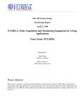
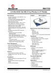
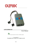
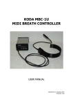
User's Manual version 1.0.6 http://LP.FutureSwTech.com Introduction LatencyPro is designed to be used as a test and diagnostic tool for those developing wireless display technologies. [The picture above is a real picture with a wired display, hence the low latency] The wireless display technology is the replacement of the VGA or HDMI cable with a wireless link. It is the goal and desire of all to achieve the lowest latency possible without sacrificing the quality of the display. If the latency is too high, interactive use of the display will be very difficult. LatencyPro is an instrument which can be used to measure the latency of a wireless display. This is accomplished by using two sensors, one on the local display and the second on the wireless display in clone or duplicate mode. When there is a transition from dark to light, the sensor will note the time, and the difference between the time of sensor1 and sensor0 will be the latency. This instrument can also measure how closely the audio and video on the wireless display are synchronized. This is accomplished by playing a sound at the time of the transition from black to white. In this case, the LatencyPro will detect the sound as well as the transition from dark to light on the screen. If the audio is detected before the screen transition occurs, the audio/video synchronization (AV sync) will be reported as a negative number. If the audio occurs after the screen transition, the AV sync will be reported as a positive number. It should be noted that TV's will sometimes add latency in order to be able to play the video smoothly. So, if you are attempting to measure latency introduced by a wireless display adapter, you should use a low latency monitor as the display device for your device under test. In fact there is an inherent latency for wired HDMI, so measuring the latency between a wired low latency monitor and the same model monitor for the wireless display will give the most accurate results for the wireless display adapter. Trademarks are the property of their respective owners. Parts LatencyPro 2 light sensors (one black wire, one white wire for convenience) and GearTie's 1 Stereo RCA male to 1/8th inch stereo phone plug (for AV sync measurement, not needed for latency measurement) 1 USB cable (for power and serial data collection) Ground loop isolator. May be needed in-line with the audio cable for measuring audio/video synchronization. First time use Sensor placement With your wireless display operational, make sure your display topology is in duplicate or clone mode. Use the GearTie's to hold sensor0 over the local screen, and sensor1 over the wireless display. Use your creativity but here is an example of how this can be done. The next image shows that if you flex the sensor past the point where it will sit when placed on the display, the GearTie will have a spring effect, lightly pressing the sensor against the screen. Naturally something similar can be done on the wireless display [TV]. You can place the sensors over the LatencyPro software application to facilitate the white/black transitions or you can simply use any black/white windows to trigger a latency measurement. A command window can be used for the black and the notepad app without text can be used for white if you like. If you place them both under the sensor and then click on one of them on the task bar, it will alternate the two windows causing a white/black transition. The LatencyPro has been designed to trigger on a black to white transition. The two sensors have been provided with different color wire for your convenience. This will make it easier for you to know which sensor to place on your local display and which to place on your wireless display. You can use either black or white for either sensor interchangeable, but once you calibrate your LatncyPro (next section), you will get the best results by continuing to plug the same color sensor into the sensor0 and sensor1 jacks. Software/Firmware/Drivers A Microsoft Windows based software application is available to help you get the most out of your LatencyPro. You can download this software as well as drivers and firmware updates from the LatencyPro download page. http://LP.FutureSwTech.com/#downloads Firmware Firmware can be updated from a Windows computer. Download the firmware update from the website, unzip the folder and run the update.bat file with the COM?? port as a parameter. The firmware is updates using avrdude from winavr which was included with the Arduino software package. Drivers Drivers are optional if simply looking at the onboard LCD display. However if you wish to collect data for statistical analysis, each data point can be collected and visualized using the build in serial terminal option and graph view, or by using a COM port terminal program such as putty. Software LatencyPro.exe is the application and there is no installation. Preferences are stored in the registry, and can be removed if you no longer wish to use the software. The registry key to delete is: HKEY_CURRENT_USER\Software\Future Software Technologies\LatencyPro Upon launching LatencyPro.exe, if you see the following notice spanning the entire width of you screen warning you that Windows has protected you, click the 'More info' link to allow the application to run. This should only occur the first time you copy the LatencyPro application to a new computer. On clicking the 'More info' link, you will probably see something like the following. On clicking the button which says 'Run anyway', the application will appear as two separate windows shown below. The first window shown is the control panel and the second is the latency sensor trigger. The trigger window can be resized for your convenience. As is states, you computer should be in clone or duplicate mode to measure latency. The faster display will be the laptop display or a wired monitor. The slower display will be the wireless display. In clone mode the same trigger window will appear on both display's but the wireless one will be update later than the wired display. The difference in time between the two displays, which we call the latency, is what we will be measuring. Upon clicking the play button, the text will disappear and the interior of the trigger window will alternate between black and white. The measurement is triggered when the sensor detects a change from black to white. To measureAV sync, you will need to check the 'Audio ping' box and plug the audio cable into the line or speaker output of the monitor or TV and then connect the other end to the Audio jack on the LatencyPro. If your unit (Hardware version1.0) was shipped with a ground loop isolator, you may need to use it in-line with the audio cable. The cable provided is intended to plug into the red/white RCA jacks on the back of a TV. If you will be using a 1/8th inch headphone jack, you may need to provide your own cable. When the 'Audio ping' is checked, a short tone is played when the trigger changes from black to white. If the audio cable is plugged into the LatecyPro it will be monitoring both the video and the audio and can then measure the difference in time between the black/white screen switch and the audio ping. This will be displayed in milliseconds, with a negative number meaning the audio played ahead of the video change. If the 'Test mode' box is checked, the trigger window will appear as follows. This provides a way to test your LatencyPro in a more controlled environment with known latency and AV sync values. The right hand side of the 'Test mode' trigger window lags the left side by one second. So if you place the sensors as suggested, your readings show a latency close to 1000 milliseconds. If testing AV sync, the value should be a relatively small number, but will vary from one monitor or TV to another. [A wired AV sync result of your remote display can be used as an offset or adjustment to add or subtract from your wireless test results.] WARNING: If you have the audio cable plugged into the LatencyPro, you must have the audio ping enabled otherwise, it will keep waiting for the ping and will not report the latency. For discussion on the 'Open terminal and graph' option, see the section on Data collection. Calibration Your LatencyPro has been initialized with sensor threshold values but for best results, it can easily be calibrated with your sensors and the brightness of your displays. There are two methods of calibrating your LatencyPro. The first one, Auto calibration, triggered from the LatencyPro application, is by far preferred and is orders of magnitude easier to perform. Auto calibration To perform auto calibration, you must have the drivers installed and have the LatencyPro connected to the computer running the LatencyPro application. Then place the sensors in the recommended locations, plug in the audio cable (of course make sure that you can play audio) an then click the 'Auto calibrate' button. The calibration will take about one second and the results will be saved on the LatencyPro for future use. However, considering how easy it is to calibrate, it is recommended that calibration be performed before each use, for beast results. The auto calibration actually does even more than the manual calibration, by calibrating the audio noise threshold, and the audio ping level. Manual calibration To enter calibration mode, press the 'calibrate' button as you power on your LatencyPro (plug the USB cable into a computer or USB hub). After the welcome screen, the display will inform you that you have entered calibration mode. Simply follow the directions on the LatencyPro, pressing the 'calibrate' button to record the white/black samples for each sensor on their respective screens. Calibrating... Release button After releasing the button, the display should read: Place sens 0 on white then press Place the sensor that is plugged into the sensor0 jack on something white on your local display, then press the calibrate button. Place sens 0 on black then press Place the sensor that is plugged into the sensor0 jack on something black on your local display, then press the calibrate button. Place sens 1 on white then press Place the sensor that is plugged into the sensor1 jack on something white on your local display, then press the calibrate button. Place sens 1 on black then press Place the sensor that is plugged into the sensor1 jack on something black on your local display, then press the calibrate button. This procedure will record the readings for your individual sensors based on the brightness and darkness of each of your displays. The readings will be stored in the memory of your LatencyPro and will be used in calculating the transitions. If you switch the roles of your black/white wire sensors, or your display brightness is very different from when you last calibrated, you should calibrate your LatencyPro again. Data collection If Arduino drivers have been installed (see driver downloads), and 'Open terminal and graph' is checked, LatencyPro has been designed to automatically open a serial terminal to receive the data. If the serial terminal does not open when pressing the play button, it is most likely because a COM port with the work "Arduino" does not exist or it cannot be opened. If it exists and can be opened, you will see a window as show below. From it, you can copy and paste the text and save it as a *.csv file. Each time you press the start button, the previously opened terminal will be closed and a new one will be opened. If you do not save it, any data in the previous terminal will be lost. If for some reason you wish to use your own serial terminal software such as putty (http://www.putty.org/), uncheck the option 'Open terminal and graph' and you will be able to connect and receive the serial data using the following parameters. Data collection allows you to capture every latency [and AV Sync] reading, for statistical or visual analysis. You can discover the COM port number of your device by looking in the device manager under 'Ports (COM & LPT).' Your device should appear as 'Arduino Uno (COM??).' You can set the COM parameters as follows: baud: 115200 data bits: 8 stop bits: 1 parity: none flow control: none The LatencyPro software has been further enhanced to provide a simple graphical view of the data. The plot will not scroll if data is collected over a long period of time. When it reaches the right edge, it will scroll around and begin overwriting oldest data. If this wraparound occurs, the serial terminal will still contain all the data logged. Debugging Debug mode is for advanced users. It will dump sensor readings and timestamps to the serial port. This could be useful if you feel your sensors are not working correctly. To benefit from debug mode, you will need to have the USB/serial port drivers installed and have a serial port terminal to see the data (see data collection). A lot of data will be streaming over the COM link, so performance of the LatencyPro device might be affected. So as to minimize the effect of streaming data over the COM port, the data is collected in a circular buffer and then only the last 200 points are dumped once a number is reported. To enter this mode, press and hold the debug button as the LatencyPro is powering up. If you see the word debug appear on the screen after the welcome/version screen, then you know you have entered debug mode and you can release the button. The second use of the debug button is to press it at any time whether in debug mode or not and all sensor data will be dumped to the COM port. This may be useful because data may not be logged unless the sensors are triggered. In this case, even in debug mode, press the debug button and you should receive a lot of sensor readings. This option is available even when you are not in debug mode, but remember that it may affect the performance in obtaining the actual measurements. Trouble shooting If you have the audio cable plugged into the LatencyPro, you must have the audio ping enabled otherwise, it will keep waiting for the ping before it reports the latency. If the audio level is not loud enough, it may affect the LatencyPro's ability to pick up the ping in a timely manner. Play with your audio volume to find the optimum level for performance, without being too loud and annoying.