1
ACT-DMCIII OPERATION MANUAL
1.
Desktop Machining Center DMC-III System Description
Advanced Control Tech, GPK Group Inc. is proud to introduce the next generation of its
truly desktop CNC machine, the DMC-III system. The system contains a standard Windows
PC with ACTMach3 software and a DMC-III milling machine. Monitor, keyboard and
mouse are not included. The user can select their own according to their preferences. The
system also includes a toolbox containing the following items for turnkey operation:
2 pairs of easy to use clamp sets,
Few selected collets and milling bits,
Tool change wrenches,
Wrench and sockets for moving axes manually,
4 handlebars for moving the machine.
Printer port cable and power line cables.
The DMC-III is a full function 3-axis CNC milling machine with support for an optional 4th
rotational axis expansion. It is a compact design with a built-in CNC controller in a single
piece of equipment.
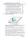
The system will come in a wooden crate. To unpack the system, please remove the screws at
the bottom of the crate. The wooden box can then be separated from the pallet. The machine
is bolted on the pallet. Remove the nuts and attach the 4 provided handlebars to the machine
on both sides for moving the machine.
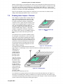
1.1
CNC controller
The CNC controller for DMC-III is compacted in a single box located behind the gantry of
the X axis. The controller box includes the power supply and electronic boards for the 3-axis
motion control and brushless motor control for the spindle driver. A 120V regular household
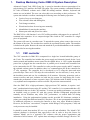
power line is plugged into the controller box. A parallel port is located in the controller box
to be connected to the PC. The controller box also provides power supply and PC control to
the optional coolant system. In addition, there is a communication port in the controller for
4th axis expansion. The controller box is developed by ACT using the latest and most
powerful chips. There are 5 CPU chips for each controller: one for each axis (3 axes), one for
the brushless motor and one for coordination of all motions. Necessary protection such as
current overflow and optic isolation are built into the system for long lasting life. It also
matches the performance of more expensive large CNC machines with its ability to carry out
very sophisticated computation to realize real time 3D precision contour motions.
Since the DMC-III is a high performance, high precision CNC machine, it requires “realtime” synchronization between the PC and the CNC controller. It is recommended that a PC
is dedicated for the use of this CNC machine. To ensure top quality performance, we provide
an installed, ready to operate PC with this system. Because background programs that
normally run on Windows may affect CNC performance, we turned them off during
installation. Using the predetermined settings on this provided PC eliminates variation in
printer port voltage that different brand PCs may have. We do not recommended installation
of additional programs or accessing the Internet as they may affect Windows behavior.
However, for the users’ convenience, Computer Aided Design (CAD) programs, CAM, and
word processors may be installed.
It should be noted that modern PCs are very powerful and affordable. The Mach3 CNC
software platform is developed from open-source code in order to keep the license fee
minimal. Mach3 can be a powerful CNC software with the proper organization and
utilization of all its features. ACT exploits these advantages to build a strongly effective CNC
controller at an affordable price. Its performance is comparable to major CNC controllers for
larger machines.
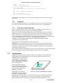
1.2 DMC-III Mechanical System
The machine frame and the T slot table are built with cast iron for rigidity and lasting life.
Precision ball screws and linear guide rails are used for all 3 axes. The machine is gantry
designed along the X axis. The tool can move in both the X and Z axes while the T slot table
moves along the Y axis in order to maximize the size of the working area. The travel distances
for X, Y, and Z axes are 12”, 8”, and 6”. A clamping system developed by ACT works with
the T slot table to allow users to secure their work piece(s) without using a vise. All parts in
the Z axis are built from precision aluminum alloy 6061 making it strong and light weight.
The machine is calibrated to ensure the alignment accuracy of the 3 axes are within 0.001” for
the entire working area. The spindle motor is a high torque, variable speed (1,500 rpm to
12,000 rpm) brushless motor. The standard ER16 collet is used which allows the user to
secure tool bits up to 10 mm in diameter. Finally, to eliminate motor vibrations, a timing belt
is used to connect the motor driver and the spindle.
1.3
CNC software
To make operation easier for our users, we modified the original Mach3 software to be used
strictly with the DMC-III hardware. This modified version of the software is called
“ACTMach3”. Chapters 1 to 6 of this manual describe the DMC-III machine and the
operation of ACTMach3. Chapter 7 and beyond are general descriptions of G codes from the
Mach3 manual.
You are advised to join one or both of the online discussion for Mach3. Links to join are at
www.machsupport.com ACT has spent a great deal of effort to simplify the Mach3 program
and make it easy to use. By reading the first 6 chapters of this manual, the user shall be very
familiar with the system. Since all of the interfaces are graphic displays, the user can spend
time to play with the CNC software while DMC-III is powered off.
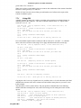
1.4 System Set up and Installation
The DMC-III system setup is simple and easy:
Step 1: Set up the PC by connecting the power to the PC rear panel and plug in the necessary
connections for the mouse, keyboard and monitor.
Step 2: Connect one end of the 25-pin connector to the PC parallel port and the other end to the
DMC-III controller box, located at the back of the machine.
Step 3: Make sure the DMC-III power switch is in the OFF position (O=OFF I=ON) and connect
the power cord to the DMC-III Machine.
Step 4: Turn on the PC. When Windows is ready, start the ACT MACH3 mill program.
Caution: Always turn on the PC before turn on the machine and turn off the machine before turn off
the PC. Since the Window booting process can send voltages to cause the spindle turning.
Step 5: Turn on the DMC-III power switch. Music will play indicating that the machine is on.
Step 6: Once the system is powered on, click the red “RESET” button.” The button and the light on
the machine will turn green showing that the system is ready to operate. The first thing the
user must do is to click “Ref All Home” button. The machine will slowly move to find the
origins.
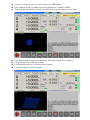
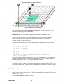
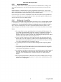
Step 7: click “Load G-code.” A test program called “roadrunner” can be loaded. You will see that the
toolpaths are located outside of the machine boundary (the white dash line is the machine
boundary). If you do not see the white dash line, please click “Display Mode”.
Step 8: Now, we need to move the toolpaths into the machine boundary. Use arrow keys to move the
X and Y axes to the lower left corner and page-down to move the Z axis. Then click the “X”,
“Y” and “Z” letter to set the new zero position.
Step 9: Click “regenerate toolpath.” It will redraw the toolpath and make sure it is within the machine
boundary. Then you can click “start” to run the program. Before running the program, make
sure the entire table is free of obstacles.
Note: If you move the tool outside of the machine boundary by accident, you will hear the click
sound from the motor, please reverse the motion such that the tool is within the boundary. You
need to reference all home to recalibrate the position before doing any precision machining.
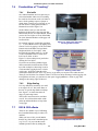
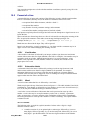
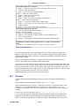
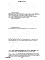
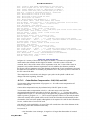
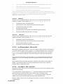
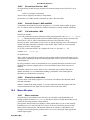
DMC-III Controller Connector Panel
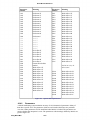
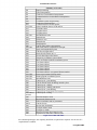
1.5 System specification
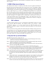
DMC-III Specifications
Travel Distance X, Y, Z
Table Size W x D
T slot width
Number of T slots
Machine Dimension W x D x H
Gantry clearance from table
Motion support
Driver Screw
Motor driver
Motion resolution
Machine repeatability
Position accuracy in the entire
machining area
Slew rate X, Y, Z
Spindle
Spindle driver motor
Spindle speed
Spindle motor to spindle
Coolant system
4th rotation axis
Total weight
12” x 8” x 6”
22” x 20”
7/16” or 11mm
5
27” x 30” x 31” *1
6.25” *2
HIWIN 20mm linear guide rail with double blocks
and final machining in pairs for each axis
Preload 20mm ball screw with zero backlash
Micro step motor with ACT optimal digital
controller *3
2 microns
0.0001”
0.001”
60”/m, 60”/m, 60”/m
Standard ER11 with ¼” diameter or ER16 with 3/8”
diameter max tool bit
Brushless DC motor with 1/3 HP
Variable 1,500 to 12,000 rpm directly controlled by
CNC program
Pulley with timing belt to isolate any motor vibration
to the spindle
Ready can be controlled by CNC program
Ready to expand with communication port
260 lb (400 lb for the complete system shipping
weight)
It is a single piece machine, all power and control units, except PC, are built-in.
*2 It is only a little more than z travel distance. Since we provide the special designed work piece(s)
holding devices for blocks and thin plate, all work piece(s) can be secured directly on the T slot table,
user does not need a vise to hold the work piece.
*3 This micro step controller was developed by ACT. We guarantee no step missing in normal
operation. We have tested the machine at full speed (rapid rate) in all axes continuously for many
hours at a time; the motors did not get hot at all, nor was there any loss of position. There are 5 micro
processors in each controller, one for each of the 3 axis, one for the spindle motor and one for the
coordination of all motions. The electronic system is thoroughly tested for temperature variations and
vibrations for reliability and long life.
*1
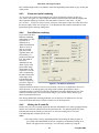
1.6 Windows XP System Optimization Guide
The PC we provided has been installed with the Windows XP operating system. The system has been
optimized for the best performance of the DMC-III machine during this installation. The user does not
have to change the Windows setup. However, in case the system setup has been changed, the user
should make sure that the system does not access the Internet. Additionally, the following functions
must be disabled:
1. Automatic Updates
1. Right click “My Computer” and select “Properties”
2. Click “Automatic Updates” tab.
3. Uncheck “Keep my computer updated.”
4. Click OK.
2. Remote Assistance
1. Right Click “My Computer” and select “Properties”
2. Click “Remote” tab.
3. Uncheck "Allow Remote Assistance Invitations”
4. Click OK.
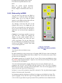
1.7
Machine Power Off sequence
Step 1: Click the RESET button located on the lower left side of the screen. This will
disable the machine and turn the RED light on, RDY led flashing
Step 2: Turn machine power off (make sure to do this before exiting the program)
Step 3: Exit from ACTMach3 software program
Step 4: Log off or shut down from Windows system
1.8 Safety Rules for using CNC machine
Any machine tool is potentially dangerous. Computer controlled machines are potentially more
dangerous than manual ones. It is recommended that the user spends some time to play with the
software before turning on the DMC-III power switch. We designed the machine to be very reliable
and easy to operate, however, ACT accepts no responsibility for any damage or injury caused by
improper use of the machine. It is your responsibility to ensure safety of operation.
The following rules are recommended for safety:
Wear safety glasses
Make your workshop “kid-proof”
Keep work area clear
Keep away from turning spindle and tools
Make sure your program toolpath display is within the machine boundary before running the
program (see Display mode)
Dry run your program before running the actual parts
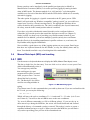
2.
2.1
DMC-III CNC machining systems
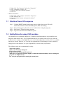
Parts of a machining system
This chapter will introduce you to terminology used in the rest of
this manual and allow you to understand the purpose of the
different components in a numerically controlled milling system.
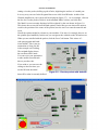
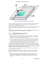
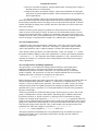
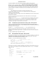
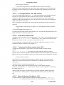
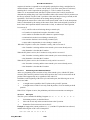
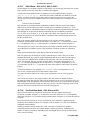
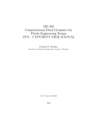
The main parts of a system for a numerically controlled mill are shown in figure 1.1
Figure 2.1 - Typical NC machining system
The designer of a part generally uses a Computer Aided Design/Computer Aided
Manufacturing (CAD/CAM) program or programs on a computer (1). The output of
this program, a part program, is often called "G-code" and is transferred by a network
or a USB memory stick (2) to the Machine Controller (3). The machine Controller is
responsible for interpreting the part program to control the tool which will cut the
work-piece to a designed part. The axes of the Machine (5) are moved by screws,
racks or belts which are powered by servo motors or stepper motors. The signals from
the Machine Controller are amplified by the Drives (4) so that they are powerful
enough and suitably timed to operate the motors.
The Machine Controller (3) can control starting and stopping of the spindle motor
(and the motor speed), all axes motion, turn coolant on and off and will check that a
part program or Machine Operator (6) is not trying to move any axis beyond its limits.
Because the commands of a G-code program can request complicated coordinated
movements of the machine axes, the Machine Controller has to be able to perform a
lot of calculations in "real-time" (e.g. cutting a helix requires a lot of trigonometric
calculation). Historically this made it an expensive piece of equipment.
2.2 How DMC-III fits in
The DMC-III system provides completed functions of (3), (4) and (5) in Fig. 2.1.
DMC-III system contains a PC and a milling machine. The CNC software package
and the Windows system are installed in the PC. The CNC software developed by
ACT is based on modification of the Mach3 program. ACT licensed Mach3 program
and simplified it into one user friendly system. The PC and CNC controller built into
the milling machine provide the combined functions of (3) and (4), as shown in Fig.
2.1. The PC will perform part of function (3) with graphic display. The CNC
controller performs the rest part of function (3) and the completed function (4).
3.
CNC Software Overview
The CNC software is modified by ACT using the Mach3 software platform. We
simplified the display and made it easy to use. The display screens look like most of
the expensive large CNC machines. The following screen will be displayed when
user opens the ACTMill software installed in the PC.
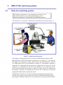
3.1
Display Screens
As you can see, most of the CNC operation functions are in this screen and you
are ready to try out all of these functions. The black window in the screen will
display the actual tool moving. The “Display mode” will display the boundary of
the machine. It will be much easier for the user to play with the software and see
how the tool moves in the screen with the machine powered off.
3.2.1 Types of object on screens
You will see that the Program Run screen is made up of the following:
Buttons (e.g. Reset, Stop Alt-S, etc.)
DROs or Digital Readouts. Anything with a number displayed will be a
DRO. The main ones are, of course, the current positions of the X, Y, Z, A,
B & C axes.
LEDs (in various sizes and shapes)
G-code display window (with its own scroll bars)
Toolpath display (blank square on your screen)
There is one important type of control that is not on the Program Run screen:
MDI (Manual Data Input) line
Buttons and the MDI line are your inputs.
DROs can be displays or can be used as inputs. The background color changes
when you are inputting.
The G-code window and Toolpath displays are informational. You can,
however, manipulate both of them (e.g. scrolling the G-code window,
zooming, rotating and panning the Toolpath display)
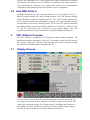
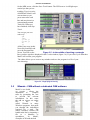
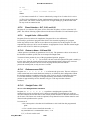
The ACTMach3 is simplified into 4 screen buttons as shown in the Fig.3.3.
They are Run Program Alt-1, MDI Alt-2, ToolPath Alt4 and Tool Offsets Alt5.
Figure 3.3 - The screen selection buttons
3.2.2 Using buttons and shortcuts
On the standard screens most buttons have a keyboard hotkey. It is shown after the
name on the button itself or in a label near it. Pressing the named key when the screen is
displayed is the same as clicking the button with the mouse. You might like to try using
the mouse and keyboard shortcuts to turn on and off the spindle, to turn on Flood
coolant and to switch to the MDI screen. Notice that letters are sometimes combined
with the Control or Alt keys. Although letters are shown as uppercase (for ease of
reading) do not use the shift key when using the shortcuts.
In a workshop it is convenient to minimize the times when you need to use a mouse.
The arrow keys can be used to move the X and Y axes and page up and page down is
used to move the Z axis up and down. It is noted that the left and right arrow keys
logically move the tool to the left and right. The up and down arrow keys move the
table forward and backward where the table moves in opposite direction of the arrow
direction. It is because that the Y direction is defined as the tool moving direction. The
tool moves relative to the table in the opposite direction.
If a button does not appear on the current
screen then its keyboard shortcut is not
active.
There are certain special keyboard
shortcuts which are global across all
screens. Chapter 5 shows how these are set
up.
3.2.3 Data entry to DRO
You can enter new data into any DRO by
clicking on it with the mouse, clicking its
hotkey (where set) or by using the global
hotkey to select DROs and moving to the one
that you want with the arrow keys.
Try entering a feed rate like 45.6 on the
Program Run screen. You must press the
Enter key to accept the new value or the Esc
key to revert to the previous one. Backspace
and Delete are not used when inputting to
DROs.
Caution: It is not always sensible to put your
own data into a DRO. For example the
display of your actual spindle speed is
computed by Mach3. Any value you enter
will be overwritten. You can put values into
the axis DROs but you should not do it until
you have read Chapter 7 in detail. This is not
a way of moving the tool!
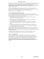
3.3
Jogging
Figure 3.4 - Jog controls
(use Tab key to show and hide
this)
You can move the tool relative to any
place on
the table manually by using various types of Jogging. DMC-III moves the tool along the
X and Z axes and the machine table moves along Y axis. We will use the words "move
the tool" here for simplicity.
The jogging controls are of a special “fly-out” screen. This is shown and hidden by using
the Tab key on the keyboard. Figure 3.4 gives a view of the fly-out. Pressing Tab key again
will make the fly-out disappear.
You can use the keyboard for jogging. The arrow keys are set by default to give you
jogging on the X and Y axes and Pg Up/Pg Dn jogs the Z axis. You can re-configure
these keys (see Chapter 5) to suit your own preferences. You can use the jogging keys on
any screen with the Jog ON/OFF button on it.
In figure 3.4 you will see that the Step LED is shown lit. The Jog Mode button toggles
between Continuous and Step modes:
In Continuous mode the chosen axis will jog for as long as you hold the key down. The
speed of jogging is set by the Slow Jog Percentage DRO. You can enter any value from
0.1% to 100% to get whatever speed you want. The Up and Down screen buttons beside
this DRO will alter its value in 5% steps. If you depress the Shift key then the jogging will
occur at 100% speed whatever the override setting. This allows you to quickly jog to near
your destination and the position accurately.
In Step mode, each press of a jog key will move the axis by the distance indicated in the
Step DRO. You can set this to whatever value you like. Movement will be at the current
Feed rate. You can cycle through a list of predefined Step sizes with the Cycle Jog Step
button.
Overview of ACTMach3
Rotary encoders can be interfaced (via the parallel port input pins) to Mach3 as
Manual Pulse Generators (MPGs). It is used to perform jogging by turning its knob
when in MPG mode. The buttons marked Alt A, Alt B and Alt C cycle through the
available axes for each of the three MPGs and the LEDs define which axis is currently
selected for jogging.
The other option for jogging is a joystick connected to the PC games port or USB.
Mach3 will work with any Windows compatible "analog joystick" (so you could even
control your X axis by a Ferrari steering wheel!). The appropriate Windows driver
will be needed for the joystick device. The 'stick is enabled by the Joystick button and,
for safety, must be in the central position when it is enabled.
If you have a joystick with throttle control, then this can be configured either to
control the jog override speed or the control the feed rate override (see Chapter 5).
Such a joystick is a cheap way of providing very flexible manual control of your
machine tool. In addition, you can use multiple joysticks (strictly Axes on Human
Interface Devices) by installing manufacturer's profiler software or, even better, the
KeyGrabber utility supplied with Mach.
Now would be a good time to try all the jogging options on your system. Don't forget
that there are keyboard shortcuts for the buttons, so why not identify them and try
them. You should soon find a way of working that feels comfortable.
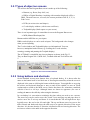
3.4
Manual Data Input (MDI) and teaching
3.4.1 MDI
Use the mouse or keyboard shortcut to display the MDI (Manual Data Input) screen.
This has a single line for data entry. You can click on it to select it or use press Enter
which will automatically select it.
You can type any valid line
that could appear in a part
program and it will be executed
when you press Enter. You can
discard the line by pressing
Esc. The Backspace key can be
used for correcting mistakes in
Figure 3.4 - MDI data being typed
typing.
If you know some G-code commands then you could try them out. If you are not familiar with
the G code, you can try the following:
G00 X1.6 Y2.3
Which will move the tool to coordinates X = 1.6 units and Y = 2.3 units. (it is G zero
not G letter O). You will see the axis DROs move to the new coordinates.
Try several different commands (or G00 to different places). If you use the up or
down arrow keys during the MDI line, the screen will scrolls backward and forward
through the history of commands you have entered. This makes it easier to repeat a
command without having to re-type it. When you select the MDI line you will notice
a fly-out box providing you a preview of the remembered text.
A MDI line (or a block of G-code) can have several commands on it, and they will be
executed in the "sensible" order as defined in Chapter 10. It is not necessarily from left
to right. For example setting a feed rate by G-code such as F2.5 will take effect before
any feed speed movements even if the F2.5 appears in the middle or even at the end of
the line (block). If you are in doubt about the order to be executed in each line, try to
type several separate MDI command lines.
3.4.2 Teaching
Mach3 can remember a sequence of lines that you enter using MDI and write them to a
file. This can then be run again and again as a G-code program.
Overview of ACTMach3
On the MDI screen, click the Start Teach button. The LED next to it will light up to
remind you that you are
teaching. Type in a series
of MDI lines. Mach3 will
execute them as you
press return after each
line and store them in a
conventionally named
Teach file. When you
have finished, click Stop
Teach.
You can type your own
code or try:
g21
f100
g1 x10 y0
g1 x10 y5
x0
y0
All the 0 are zeros in this.
Next click Load/Edit and
go to the Program Run
Figure 3.5 - In the middle of teaching a rectangle
screen. You will see the
lines you have typed are displayed in the G-code window (figure 3.6). If you click Cycle Start then
Mach3 will execute your program.
The editor allows you to correct any mistakes and save the program in a file of your
own choosing.
Figure 3.6 - Taught program running
3.5
Wizards - CAM without a dedicated CAM software
Mach3’s use of addon screens
allows the
automation of
complex
tasks by prompting the user
to provide the relevant
information. In this sense
the add on screens are rather
like
the
socalled Wizards in many
Windows programs that guide
you through the information
required for a task. The
classic Windows Wizard will
handle tasks line by importing a
file to a database or
spreadsheet.
In
Mach3,
examples of Wizards include
Figure 3.7 - Table of Wizards from Wizard menu
Overview of ACTMach3
cutting a circular pocket, drilling a grid of holes, digitizing the surface of a model part.
It is easy to try one out. In the Program Run screen click Load Wizards. A table of the
Wizards installed on your system will be displayed (figure 3.7). As an example, click on
the line for Circular pocket, which is in the standard Mach3 release, and click Run.
The Mach3 screen currently displayed will be replaced by the one shown in figure 3.8.
This shows the screen with some default options. Notice that you can choose the units to
work in, the position of the centre of the pocket, how the tool is to enter the material and
so on.
Not all the options might be relevant to your machine. You may, for example, have to set
the spindle speed manually. In this case you can ignore the controls on the Wizard screen.
When you are satisfied with the pocket, click the Post Code button. This writes a Gcode part program and loads
it into Mach3. This is just an
automation of what you did
in the example on Teaching.
The toolpath display shows
the cuts that will be made.
You can revise your parameters
to take smaller cuts and such
then re-post the code.
If you wish to, you can save the
settings so the next time you
run the Wizard, the initial
Figure 3.8 - Circular pocket with defaults
data will be what is currently defined.
Figure 3.9 - Circular Pocket with values set and code posted
Overview of ACTMach3
When you click Exit, you will be returned to the main Mach3 screens so you can
run the Wizard-generated part program. This process will often be quicker than
reading the description here.
Figure 3.10 - The result of Circular Pocket ready to run
3.6
Running a G-code program
Now it is time to input and edit a Part Program. You will normally be able to edit
programs without leaving Mach3 but, as we have not yet configured it to know which
editor to use, it is easiest to set up the program outside of Mach3.
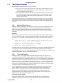
Use Windows Notepad to enter the following lines into a text file and save it
in a convenient folder (My Documents perhaps) as spiral.tap
You must choose All Files in the Save As Type drop-down or Notepad will append
.TXT to your filename and Mach3 will not be able to find it.
g20 f100
g00 x1 y0 z0
g03 x1 y0 z-0.2
g03 x1 y0 z-0.4
g03 x1 y0 z-0.6
g03 x1 y0 z-0.8
g03 x1 y0 z-1.0
g03 x1 y0 z-1.2
m00
If
start
from
position, y will
limit
i-1
i-1
i-1
i-1
i-1
i-1
j0
j0
j0
j0
j0
j0
home
exceed
Again all "0" are zeros in this. Don't forget to press the Enter key after m00. Use the
File>Load G-code menu to load this program. You will notice that it is displayed in the
G-code window. On the Program Run screen you can try the effect of the Start Cycle,
Pause, Stop, and Rewind buttons and their shortcuts. As you run the program you may
notice that the highlighted line moves in a peculiar way in the G-code window. Mach3
reads ahead and plans its moves to avoid slowing down the toolpath . This look ahead
is reflected in the display and when you pause. You can go to any line of code scrolling
the display so the line is highlighted. You can then use Run from here.
Overview of ACTMach3
Note: You should always run your programs
from a hard drive not a floppy drive or USB
"key". Mach3 needs high-speed access to the
file, which it maps into memory. The program
file must not be read-only.
3.7
Toolpath display
3.7.1 Viewing the toolpath
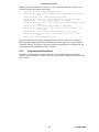
The Program Run screen has a blank square on it
when Mach3 is first loaded. When the Spiral
program is loaded, you will see it change to a
circle inside a square. You are looking straight
down onto the toolpath for the programmed part
(i.e. in Mach3Mill you are looking perpendicular
to the X-Y plane).
Figure 3.11 Toolpath from Spiral.txt
The display is like a wire model of the path the tool will follow placed inside a clear
sphere. By dragging the mouse over the window you can rotate the "sphere" to see the
model from different angles. The set of axes in the top left hand corner show you what
directions X, Y and Z are. So if you drag the mouse from the center in an upwards
direction the "sphere" will turn showing you the Z axis and you will be able to see that
the circle is actually a spiral cut downwards (in the negative Z direction). Each of the
G3 lines in the spiral program above draws a circle while simultaneously lowering the
tool 0.2 in the Z direction. You can also see the initial G00 move which is a straight
line.
You can, if you wish to, produce a display like the conventional isometric view of the
toolpath. A few minutes of "play" will soon give you confidence in what can be done.
Your display may be a different color from what is shown in figure 3.11. The colors can
be configured. See hapter 5.
3.7.2 Panning and Zooming the toolpath display
The toolpath display can be zoomed by dragging the cursor in its window with the Shift
key depressed.
The toolpath display can be panned in its window by dragging the cursor in the
window with the Right mouse button held.
Double-clicking the toolpath window restores the display to the original perpendicular
view with no zoom applied.
Note: You cannot Pan or Zoom while the machine tool is running.
3.8 Other screen features
Finally it is worth browsing through some of the other Wizards and all the screens.
As a small challenge you might like to see if you can identify the following useful features:
A button for estimating the time that a part program will take to run on the actual
machine tool
The controls for overriding the feed rate selected in the part program
DROs which give the extent of movement of the tool in all axes for the loaded part
program
A screen that lets you set up information like where you want the Z axis to be
placed
to keep X and Y from hitting clamps etc.
4.
Basic Machining Operations
After properly following the setup steps in section 1-2:
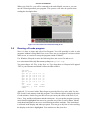
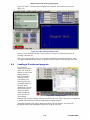
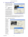
Start the program and enter the main screen.
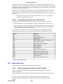
Before pressing the Reset button (located at the lower left of the screen) , the Ready indicator
shows Red status (Not Ready). Unit indicator shows in mm unit (Default setting).
After pressing the Reset button, the Ready indicator shows Green status (Ready).
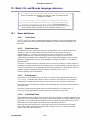
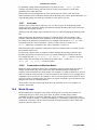
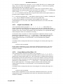
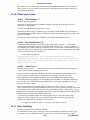
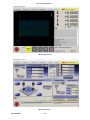
Main Screen
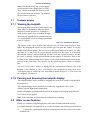
Click Load G-code button to load a G code file.
Make sure Ready indicator is Green
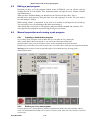
After loading program
Notice that Toolpath is outside the machine limits (Dashed line indicates machine boundaries)
Click RefAllHome to let machine locate Home positons
Wait for X/Y/Z DRO automatically set ZERO
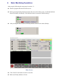
Use arrow keys to move X and Y positions to workpiece ORIGIN position.
Notice X and Y DRO show its displacement form machine HOME
You need to clear this value to set the workpiece as ZERO origin
Click character X and Y of DRO respectively (Function to set DRO to ZERO)
Then click RegenToolpath , You can click SoftLimits to prevent jogging over the limits
Click DisplayMode to toggle between display limits and toolpath of the workpiece.
Use mouse left key to rotate the toolpath,
Use Shift-mouse left key to zoom in and out toolpath
Use mouse right key to PAN toolpath
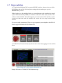
4.1 Home switches
ACT professional desktop CNCs use optical HOME switches, whenever the user clicks
RefAllHome, the tool bit will slowly move along each axis and stop at a precise
Machine Zero position.
When jogging over the machine limits, to prevent damage to the machine the control
system will automatically STOP, the indicator will turn to Red status, and the CNC
software will be disabled. When this happens, you need to turn off the machine, use the
wrench tool that came with the machine and wrench the axis away from the limit
sensors.
For prevent such circumstance, When ever you regenerate your toolpath or after Ref All
Home, toggle Soft Limits ON (Red Status ON)
ACT MACH3 will automatically stop the axis movement when jogging near the machine
limits.
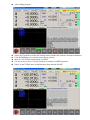
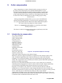
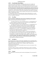
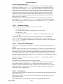
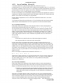
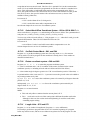
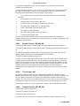
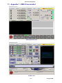
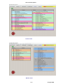
Screen image of G-code program Roadrunner.tap
Sample file locate at C:\Mach3\GCode\roadrunner.tap
5.
Hole-making
Learning objectives
Learning canned cycles (or Fixed cycles) for hole making
Identify the G-code used to program the canned cycle
Understanding initial and retract planes
The machine should behave as follows when the canned cycle is called:
Rapidly move to X & Y start location and then Z
Perform the hole making operation
Cancel the canned cycle
Return to a predetermined location and stop the cycle
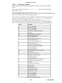
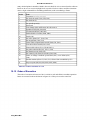
G-code for canned cycles
1.
2.
3.
4.
5.
6.
G80
G81
G82
G83
G90
G91
Cancel the canned cycle
Standard drilling cycle
Drill with timed dwell
Peck drilling cycle
Absolute dimensioning mode
Incremental dimensioning mode
When using hole making cycles, it is important to understand initial and retract plane.
These two planes are used to control vertical tool movement within the drill cycle and
between the multiple holes
1. G98 Return tool to initial plane
2. G99 Return tool to retract plane
G98 is used when extra clearance is needed to avoid collisions between the workpiece and
the tool. When using G98, a safe level should be selected but not so high as to waste time
with excessive tool movement.
G99 will cause the tool to return only to the retract plane at the end of each cycle or between
the holes, and is the preferred method for hole making when there are no obstructions or
clearance problems, especially when numerous holes are to be drilled.
If you need the extra clearance, return to initial plane (G98) to be safe. Otherwise, use return
to retract plane (G99) for fast tool retraction and making numerous holes when there are no
obstructions.
Sample program
N10
N20
N30
N40
N50
N60
N70
N80
N90
N100
N110
N120
N130
N140
N150
N160
G20 G40 G49 G54 G80 G90 G98
T01
M03 S2000
M08
G00 X2.0 Y0.0
G01 Z-2.0 F20.0
G99 G82 X2.0 Y0.682 Z-4.3 R-3.8 P2.0 F3.0
Y0.832
X3.0 Y0.84
Y0.69
G80
M05
M09
G00 X1.181 Y1.5
G00 Z-1.0
M30
Drill 4 holes retract to Z-3.8 between holes and depth 0.5” pause 2 sec before tool retraction.
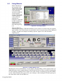
6.3
Using Wizards
Mach3 Wizards are
an extension to the
Teach facility which
allows you to define
some machining
operations using one
or more special
screens. The Wizard
will then generate Gcode to make the
required cuts.
Examples of Wizards
include machining a
circular pocket,
drilling an array of
holes and engraving
text.
Figure 6.21 - Choosing a Wizard
The Load Wizards
button displays a table of Wizards installed on your system. You choose the one required
and click Run. The Wizard screen (or sometimes one of several screens) will be displayed.
Chapter 3 includes an example for milling a pocket. Figure 6.22 is the Wizard for
engraving text.
Figure 6.22 - The Write Wizard screen
Wizards have been contributed by several authors and depending on their purpose there are
slight differences in the control buttons. Each Wizard will however have a means of posting the
G-code to Mach3 (marked Write in figure 6.22) and a means of returning to the main Mach3
screens. Most Wizards allow you to save your settings so that running the Wizard again gives
the same initial values for the DROs etc.
Using Mach3Mill
Mach3 controls and running a part program
Figure 6.23 shows a section of the Toolpath screen after the Write button is pressed on
figure 6.22.
Figure 6.23 - After running the Write wizard
The Last Wizard buttons runs the wizard you most recently used without the trouble of
selecting it from the list.
The Conversational button runs a set of wizards designed by Newfangled Solutions. These
are supplied with Mach3 but require a separate license for them to be used to generate code.
6.4
Loading a G-code part program
If you have an
existing part program
which was written by
hand or a CAD/CAM
package then you
load it into Mach3
using the Load GCode button. You
choose the file from
a standard Windows
file open dialog.
Alternatively you can
choose from a list of
recently used files
which is displayed
by the Recent Files
Figure 6.24 - Loading G-Code
screen button.
When the file is chosen, Mach3 will load and analyze the code. This will generate a toolpath for
it, which will be displayed, and will establish the program extremes.
The loaded program code will be displayed in the G-code list window. You can scroll
through this moving the highlighted current line using the scroll bar.
6-15
Using Mach3Mill
Mach3 controls and running a part program
6.5
Editing a part program
Provided you have a G-code program loaded in the ACTMach3, you can edit the code by
clicking the Edit G-Code button. Your nominated editor will open in a new window with the
code loaded into it.
When you have finished editing you should save the file and exit the editor. This is
probably most easily done by using the close box and replying Yes to the "Do you want to
save the changes?" dialog.
While editing, Mach3 is suspended. If you click in its window it will appear to be locked up.
You can easily recover by returning to the editor and closing it.
After editing the revised code, it will again be analyzed with the toolpath and extremes. You
can regenerate the toolpath at any time using the Regenerate button.
6.6
Manual preparation and running a part program
6.6.1
Inputting a hand-written program
If you want to write a program "from scratch" then you can either do so by running the
editor outside Mach3 and saving the file or you can use the Edit button with no part
program loaded. In this case you will have to Save As the completed file and exit the editor.
In both cases you will have to use File>Load G-code, or Load G-code to load your new program into Mach3.
Warning: Errors in lines of code are generally ignored. You should not rely on being given a
detailed syntax check.
6.6.2
Before you run a part program
It is good practice for a part program to make no assumptions about the state of the machine when it
starts. You should therefore include G17/G18/G19, G20/G21, G40, G49, G61/G62, G90/G91, G93/G94
in your code.
Using Mach3Mill
6-16
Mach3 controls and running a part program
You should ensure that the axes are in a known reference position - probably by using the Ref
All Home button.
You need to decide whether the program starts with an S word or if you need to set the
spindle speed by hand or by entering a value in the S DRO.
You will need to ensure that a suitable feed rate is set before any G01/G02/G03 commands are
executed. This may be done by an F word or entering data into the F DRO.
Next you may need to select a Tool and/or Work Offset.
Finally, unless the program has been proved to be valid you should attempt a dry run,
cutting "air" to see that nothing terrible happens.
6.6.3
Running your program
You should monitor the first run of any program with great care. You may find that you need to
override the feed rate or, perhaps, spindle speed to minimize chattering or to optimize production.
When you want to make changes you should either do this on the "fly" or use the Pause button,
make your changes and then click Cycle Start.
7.
Coordinate systems, tool table and fixtures
This chapter explains how Mach3 works out where exactly you mean when
you ask the tool to move to a given position. It describes the idea of a
coordinate system, defines the Machine Coordinate System and shows how you
can specify the lengths of each Tool, the position of a workpiece in a
Fixture and, if you need to, to add your own variable Offsets.
You may find it heavy going on the first read. We suggest that you try out
the techniques using your own machine tool. It is not easy to do this just
"desk" running Mach3 as you need to see where an actual tool is and you
will need to understand simple G-code commands like G00 and G01.
Mach3 can be used without a detailed understanding of this chapter but you
will find that using its concepts makes setting up jobs on your machine is
very much quicker and more reliable.
7.1
Machine coordinate system
Pen-holder
Table
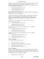
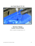
Figure 7.1 - Basic Drawing Machine
You have seen that most Mach3 screens have DROs labeled "X Axis", "Y Axis" etc. If you are
going to make parts accurately and minimize the chance of your tool crashing into
anything you need to understand exactly what these values mean at all times when you are
setting up a job or running a part program.
This is easiest to explain looking at a machine. We have chosen an imaginary machine that
makes it easier to visualize how the coordinate system works. Figure 7.1 shows what it is
like.
It is a machine for producing drawings with a ballpoint or felt tipped pen on paper or
cardboard. It consists of a fixed table and a cylindrical pen-holder which can move left and
right (X direction), front and back (Y direction) and up and down (Z-direction). The figure
shows a square which has just been drawn on the paper.
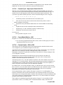
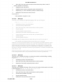
Figure 7.2 shows the Machine Coordinate System which measures (lets say in inches) from the
surface of the table at its bottom left hand corner. As you will see the bottom left corner of the
paper is at X=2, Y=1 and Z=0 (neglecting paper thickness). The point of the pen is at X=3, Y=2
and it looks as though Z=1.3.
If the point of the pen was at the corner of the table then, on this machine, it would be in its
Home or referenced position. This position is often defined by the position of Home
switches which the machine moves to when it is switched on. At any event there will be a
7-1
Using Mach3Mill
Coordinate systems, tool table and fixtures
+Z
+Y
Figure 7.2 Machine coordinate system
zero position for each axis called the absolute machine zero. We will come back to where
Home might actually be put on a real machine.
The point of the pen, like the end of a cutting tool, is where things happen and is called the
Controlled Point. The Axis DROs in Mach3 always display the coordinates of the
Controlled Point relative to some coordinate system. The reason you are having to read this
chapter is that it is not always convenient to have the zeros of the measuring coordinate
system at a fixed place of the machine (like the corner of the table in our example).
A simple example will show why this is so.
The following part program looks, at first sight, suitable for drawing the 1" square in Figure
7.1:
N10 G20 F10 G90 (set up imperial units, a slow feed rate etc.)
N20 G0 Z2.0 (lift pen)
N30 G0 X0.8 Y0.3 (rapid to bottom left of square)
N40 G1 Z0.0 (pen down)
N50 Y1.3 (we can leave out the G1 as we have just done one)
N60 X1.8
N70 Y0.3 (going clockwise round shape)
N80 X0.8
N90 G0 X0.0 Y0.0 Z2.0 (move pen out of the way and lift it)
N100 M30 (end program)
Even if you cannot yet follow all the code it is easy to see what is happening. For example on
line N30 the machine is told to move the Controlled Point to X=0.8, Y=0.3. By line N60 the
Controlled Point will be at X=1.8, Y=1.3 and so the DROs will read:
X Axis 1.8000 Y Axis 1.3000 Z Axis 0.0000
The problem, of course, is that the square has not been drawn on the paper like in figure 7.1 but
on the table near the corner. The part program writer has measured from the corner of the paper
but the machine is measuring from its machine zero position.
7.2
Work offsets
Mach3, like all machine controllers, allows you to move the origin of the coordinate system or,
in other words where it measures from (i.e. where on the machine is to considered to be zero for
moves of X, Y, Z etc.)
This is called offsetting the coordinate system.
Using Mach3Mill
7-2
Coordinate systems, tool table and fixtures
+Y
+Z
Pen-holder
Table
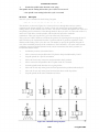
Figure 7.3 - Coordinate system origin offset to corner of paper
Figure 7.3 shows what would happen if we could offset the Current Coordinate system to the
corner of the paper. Remember the G-code always moves the Controlled Point to the
numbers given in the Current Coordinate system.
As there will usually be some way of fixing sheets of paper, one by one, in the position shown,
this offset is called a Work offset and the 0, 0, 0 point is the origin of this coordinate
system.
This offsetting is so useful that there are several ways of doing it using Mach3 but they are all
organized using the Offsets screen (see Appendix 1 for a screenshot)
7.2.1
Setting Work origin to a given point
The most obvious way consists of two steps:
1. Display the Offsets screen. Move the Controlled Point (pen) to where you want the new
origin to be. This can be done by jogging or, if you can calculate how far it is from the
current position you can use G0s with manual data input
2. Click the Touch button next to each of the axes in the Current Work Offset part of the
screen. On the first Touch you will see that the existing coordinate of the Touched axis
is put into the Part Offset DRO and the axis DRO reads zero. Subsequent Touches on
other axes copy the Current Coordinate to the offset and zero that axis DRO.
If you wonder what has happened then the following may help. The work offset values are
always added to the numbers in the axis DROs (i.e. the current coordinates of the controlled
point) to give the absolute machine coordinates of the controlled point. Mach3 will display the
absolute coordinates of the controlled point if you click the Machine Coords button. The LED
flashes to warn you that the coordinates shown are absolute ones.
There is another way of setting the offsets which can be used if you know the position of
where you want the new origin to be.
The corner of the paper is, by eye, about 2.6" right and 1.4" above the Home/Reference
point at the corner of the table. Let's suppose that these figures are accurate enough to be
used.
1. Type 2.6 and 1.4 into the X and Y Offset DROs. The Axis DROs will change (by
having the offsets subtracted from them). Remember you have not moved the actual
position of the Controlled point so its coordinates must change when you move the
origin.
7-3
Using Mach3Mill
Coordinate systems, tool table and fixtures
2. If you want to you could check all is well by using the MDI line to G00 X0 Y0 Z0. The
pen would be touching the table at the corner of the paper.
We have described using work offset number 1. You can use any numbers from 1 to 255.
Only one is in use at any time and this can be chosen by the DRO on the Offsets screen or by
using G-codes (G54 to G59 P253) in your part program.
The final way of setting a work offset is by typing a new value into an axis DRO. The
current work offset will be updated so the controlled point is referred to by the value now in the
axis DRO. Notice that the machine does not move; it is merely that the origin of
coordinate system has been changed. The Zero-X, Zero-Y etc. buttons are equivalent to typing 0
into the corresponding axis DRO.
You are advised not to use this final method until you are confident using work offsets that
have been set up using the Offsets screen.
So, to recap the example, by offsetting the Current Coordinate system by a work offset we
can draw the square at the right place on the paper wherever we have taped it down to the
table.
7.2.2
Home in a practical machine
As mentioned above, although it looks tidy at first sight, it is often not a good idea to have
the Home Z position at the surface of the table. Mach3 has a button to Reference all the
axes (or you can Reference them individually). For an actual machine which has home
switches installed, this will move each linear axes (or chosen axis) until its switch is
operated then move slightly off it. The absolute machine coordinate system origin (i.e.
machine zero) is then set to given X, Y, Z etc. values - frequently 0.0. You can actually
define a non-zero value for the home switches if you want but ignore this for now!
The Z home switch is generally set at the highest Z position above the table. Of course if the
reference position is machine coordinate Z=0.0 then all the working positions are lower and
will be negative Z values in machine coordinates.
Again if this is not totally clear at present do not worry. Having the Controlled Point (tool) out
of the way when homed is obviously practically convenient and it is easy to use the work
offset(s) to set a convenient coordinate system for the material on the table.
7.3
What about different
lengths of tool?
+Z
+Y
If you are feeling confident so far then
it is time to see how to solve another
practical problem.
Suppose we now want to add a red
rectangle to the drawing.
Table
We jog the Z axis up and put the red
Figure 7.4 - Now we want another color
pen in the holder in place of the blue
one. Sadly the red pen is longer than
the blue one so when we go to the Current Coordinate System origin the tip smashes into the
table. (Figure 7.5)
+Z
Mach3, like other CNC controllers, has
a way for storing information about the
tools (pens in our system). This Tool
Table allows you to tell the system
up to 256 different tools.
On the Offsets screen you will see
a Tool number and information about
the tool. The DROs are labeled Z-offset,
Diameter and T. Ignore the DRO Touch
Correction and
+Y
Table
Figure 7.5 - Disaster at 0,0,0!
7-4
Coordinate systems, tool table and fixtures
its associated button marked On/Off for now.
By default you will have Tool #0 selected but its offsets will be switched OFF.
Information about the tool diameter is also used for Cutter Compensation (q.v.)
7.3.1
Pre-settable tools
We will assume your machine has a toolholder system which lets you put a tool in
at exactly the same position each time.
This might be a mill with lots of chucks
or something like an Autolock chuck
(figures 7.10 and 7.11 - where the centrehole of the tool is registered against a
pin). If your tool position is different each
time then you will have to set up the
offsets each time you change it. This will
be described later.
In our drawing machine, suppose the
pens register in a blind hole that is 1"
deep in the pen holder. The red pen is
4.2" long and the blue one 3.7" long.
Figure 7.6 - Endmill in a presettable holder
1. Suppose the machine has just been referenced/homed and a work offset defined for the
corner of the paper with Z = 0.0 being the table using the bottom face of the empty pen
holder. You would jog the Z axis up say to 5" and fit the blue pen. Enter "1" (which will
be the blue pen) in the Tool number DRO but do not click Offset On/Off to ON yet. Jog
the Z down to touch the paper. The Z axis DRO would read 2.7 as the pen sticks 2.7"
out of the holder. Then you click the Touch button by the Z offset. This would load the
(2.7") into the Z offset of Tool #1. Clicking the Offset On/Off toggle would light the
LED and apply the tool offset and so the Z axis DRO will read 0.0. You could draw the
square by running the example part program as before.
2. Next to use the red pen you would jog the Z axis up (say to Z = 5.0 again) to take out
the blue pen and put in the red. Physically swapping the pens obviously does not alter
the axis DROs. Now you would, switch Off the tool offset LED, select Tool #2, jog
and Touch at the corner of the paper. This would set up tool 2's Z offset to 3.2".
Switching On the offset for Tool #2 again will display Z = 0.0 on the axis DRO so the
part program would draw the red square (over the blue one).
3. Now that tools 1 and 2 are set up you can change them as often as you wish and get the
correct Current Coordinate system by selecting the appropriate tool number and
switching its offsets on. This tool selection and switching on and off of the offsets can
be done in the part program (T word, M6, G43 and G49) and there are DROs on the
standard Program Run screen.
7.3.2
Non-pre-settable tools
Some tool holders do not have a way of refitting a given tool in exactly the same place each
time. For example the collet of a router is usually bored too deep to bottom the tool. In this
case it may still be worth setting up the tool offset (say with tool #1) each time it is
changed. If you do it this way you can still make use of more than one work offset (see 2
and 3 pin fixtures illustrated below). If you do not have a physical fixture it may be just as
easy to redefine the Z of the work offsets offsets each time you change the tool.
7.4
How the offset values are stored
The 254 work offsets are stored in one table in Mach3. The 255 tool offsets and diameters are
stored in another table. You can view these tables using the Work Offsets Table and Tool
Offsets Table buttons on the offsets screen. These tables have space for additional information
which is not at present used by Mach3.
7-5
Using Mach3Mill
Coordinate systems, tool table and fixtures
Mach3 will generally try to remember the values for all work and tool offsets from one run of
the program to another but will prompt you on closing down the program to check that you do
want to save any altered values. Checkboxes on the Config>State dialog (q.v.) allow you to
change this behavior so that Mach3 will either automatically save the values without bothering
to ask you or will never save them automatically.
However the automatic saving options are configured, you can use the Save button on the
dialogs which display the tables to force a save to occur.
7.5
Drawing lots of copies - Fixtures
Now imagine we want to draw on many sheets of
paper. It will be difficult to tape each one in the
same place on the table and so will be necessary
to set the work offsets each time. Much better
would be to have a plate with pins sticking out of
it and to use pre-punched paper to register on the
pins. You will probably recognise this as an
example of a typical fixture which has long been
used in machine shops. Figure 7.7 shows the
machine so equipped. It would be common for
the fixture to have dowels or something similar so
that it always mounts in the same place on the
table.
We could now move Current Coordinate system
by setting the work offsets #1 to the corner of the
paper on the actual fixture. Running the example
program would draw the square exactly as before.
This will of course take care of the difference in Z
coordinates caused by the thickness of the fixture.
We can put new pieces of paper on the pins and
get the square in exactly the right place on each
with no further setting up.
Fixture
Table
Figure 7.7 - Machine with two pin
fixture
Fixture
Table
Figure 7.8 - Three pin fixture
We might also have another fixture for three-hole
paper (Figure 7.8) and might want to swap between the two and three pin fixtures for
different jobs so
work offset #2
+Z
+Y
could be defined
for the corner of
the paper on the
three pin fixture.
You can, of course
define any point on
the fixture as the
origin of its offset
coordinate system.
Fixture
For the drawing
machine we would
Table
want to make the
bottom left corner
Figure 7.9 - A double fixture
of the paper be
X=0 & Y=0 and
the top surface of the fixture be Z=0.
It is common for one physical fixture to be able to be used for more than one job. Figure 7.9
shows the two and three hole fixtures combined. You would of course have two entries in the
work offset corresponding to the offsets to be used for each. In figure 7.8 the Current Coordinate
system is shown set for using the two-hole paper option.
Using Mach3Mill
7-6
Coordinate systems, tool table and fixtures
7.6
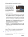
Practicalities of "Touching"
7.6.1
End mills
On a manual machine tool it is quite easy to
feel on the handles when a tool is touching
the work but for accurate work it is better to
have a feeler (perhaps a piece of paper or
plastic from a candy bar) or slip gage so you
can tell when it is being pinched. This is
illustrated on a mill in figure 7.10.
On the Offset screen you can enter the
thickness of this feeler or slip gage into the
DRO beside the Set Tool Offset button. When
you use Set Tool Offset to set an offset DRO
for a tool, then the thickness of the gage will
be allowed for.
For example suppose you had the axis DRO
Z = -3.518 with the 0.1002" slip lightly held.
Choose Tool #3 by typing 3 in the Tool DRO.
Enter 0.1002 in the DRO in Gage Block
Height and click Set Tool Offset. After
the touch the axis DRO reads Z = 0.1002
(i.e the Controlled Point is 0.1002) and
tool 3 has Z offset -0.1002.
Figure 7.11 shows this process just before
clicking Set Tool Offset.
Figure 7.10 - Using a slip gage when
touching Z offset on a mill
If you have an accurate cylindrical gage
and a reasonable sized flat surface on the
top of the workpiece, then using it can be
even better than jogging down to a feeler
Figure 7.11 - Entering Z offset data
or slip gage. Jog down so that the roller
will not pass under the tool. Now very slowly jog up until you can just roll it under the tool.
Then you can click the Touch button. There is an obvious safety advantage in that jogging a bit
too high does no harm; you just have to start again. Jogging down to a feeler or gage risks
damage to the cutting edges of the tool.
7.6.2
Edge finding
It is very difficult to accurately set a mill
to an edge in X or Y due to the flutes of
the tool. A special edge-finder tool helps
here. Figure 7.12 shows the minus X
edge of a part being found.
The Touch Correction can be used here
as well. You will need the radius of the
probe tip and the thickness of any feeler
or slip gage.
7.7
G52 & G92 offsets
There are two further ways of offsetting
the Controlled Point using G-codes G52
and G92.
When you issue a G52 you tell Mach3
that for any value of the controlled point
(e.g. X=0, Y= 0) you want the actual
machine position offset by adding the
Figure 7.12 - Edge-finder in use on a mill
7-7
Using Mach3Mill
Coordinate systems, tool table and fixtures
given values of X, Y and/or Z.
When you use G92 you tell Mach3 what you want are the coordinates of the current Controlled
Point to be values given by X, Y and/or Z.
Neither G52 nor G92 move the tool they just add another set of offsets to the origin of the
Current Coordinate system.
7.7.1
Using G52
A simple example of using G52 is where you might wish to produce two identical shapes at
different places on the workpiece. The code we looked at before draws a 1" square with a
corner at X = 0.8, Y = 0.3:
G20 F10 G90 (set up imperial units, a slow feed rate etc.) G0
Z2.0 (lift pen)
G0 X0.8 Y0.3 (rapid to bottom left of square) G1
Z0.0 (pen down)
Y1.3 (we can leave out the G1 as we have just done one)
X1.8
Y0.3 (going clockwise round shape)
X0.8
G0 X0.0 Y0.0 Z2.0 (move pen out of the way and lift it)
If we want another square but the second one with its corner at X= 3.0 and Y = 2.3 then the
above code can be used twice but using G52 to apply and offset before the second copy.
G20 F10 G90
(set up imperial units, a slow feed rate etc.)
G0 Z2.0 (lift pen)
G0 X0.8 Y0.3 (rapid to bottom left of square) G1
Z0.0 (pen down)
Y1.3 (we can leave out the G1 as we have just done one)
X1.8
Y0.3 (going clockwise round shape)
X0.8
G0 Z2.0 (lift pen)
G52 X2.2 Y2
(temporary offset for second square)
G0 X0.8 Y0.3 (rapid to bottom left of square) G1
Z0.0 (pen down)
Y1.3 (we can leave out the G1 as we have just done one)
X1.8
Y0.3 (going clockwise round shape)
X0.8
G52 X0 Y0
(Get rid of temporary offsets)
G0 X0.0 Y0.0 Z2.0
(move pen out of the way and lift it)
Copying the code is not very elegant but as it is possible to have a G-code subroutine (See M98
and M99) the common code can be written once and called as many times as you need - twice
in this example.
The subroutine version is shown below. The pen up/down commands have been tidied up
and the subroutine actually draws at 0,0 with a G52 being used for setting the corner of both
squares:
G20
G52
M98
G52
M98
G52
M30
Using Mach3Mill
F10 G90 (set up imperial units, a slow feed rate etc.)
X0.8 Y0.3 (start of first square)
P1234
(call subroutine for square in first position)
X3 Y2.3 (start of second square)
P1234
(call subroutine for square in second position)
X0 Y0 {IMPORTANT - get rid of G52 offsets)
(rewind at end of program)
7-8
Coordinate systems, tool table and fixtures
O1234
(Start of subroutine 1234)
G0 X0 Y0 (rapid to bottom left of square) G1
Z0.0 (pen down)
Y1 (we can leave out the G1 as we have just done one)
X1
Y0 (going clockwise round shape)
X0
G0 Z2.0 (lift pen)
M99 (return from subroutine)
Notice that each G52 applies a new set of offsets which take no account of any previously
issued G52.
7.7.2
Using G92
The simplest example with G92 is, at a given point, to set X & Y to zero but you can set
any values. The easiest way to cancel G92 offsets is to enter "G92.1" on the MDI line.
7.7.3
Take care with G52 and G92
You can specify offsets on as many axes as you like by including a value for their axis
letter. If an axis name is not given then its offset remains unaltered.
Mach3 uses the same internal mechanisms for G52 and G92 offsets; it just does different
calculations with your X, Y and Z words. If you use G52 and G92 together you (and even
Mach3) will become so confused that disaster will inevitably occur. If you really want to
prove you have understood how they work, set up some offsets and move the controlled point
to a set of coordinates, say X=2.3 and Y=4.5. Predict the absolute machine
coordinates you should have and check them by making Mach3 display machine
coordinates with the "Mach" button.
Do not forget to clear the offsets when you have used them.
Warning! Almost everything that can be done with G92 offsets can be done better using
work offsets or perhaps G52 offsets. Because G92 relies on where the controlled point is as
well as the axis words at the time G92 is issued, changes to programs can easily introduce
serious bugs leading to crashes.
Many operators find it hard to keep track of three sets of offsets (Work, Tool and G52/G92) and
if you get confused you will soon break either your tool or worse your machine!
7.8
Tool diameter
Suppose the blue square drawn using our machine is the outline for a hole in the lid of a
child's shape-sorter box into which a blue cube will fit. Remember G-codes move the
Controlled Point. The example part
program drew a 1" square. If the
tool is a thick felt pen then the hole
will be significantly smaller than 1"
square. See figure 7.13.
The same problem obviously
occurs with an endmill/slot drill.
You may want to cut a pocket or be
leaving an island. These need
different compensation.
This sounds easy to do but in
Figure 7.13 - Using a large diameter tool (felt pen)
practice there are many "devils in
the details" concerned with the
beginning and end of the cutting. It is usual for a Wizard or your CAD/CAM software to
deal with these issues. Mach3, however, allows a part program to compensate for the
diameter of the chosen tool with the actual cutting moves being specified as, say, the 1"
7-9
Using Mach3Mill
Coordinate systems, tool table and fixtures
square. This feature is important if the author of the part program does not know the exact
diameter of the cutter that will be used (e.g. it may be smaller than nominal due to repeated
sharpening). The tool table lets you define the diameter of the tool or, is some applications, the
difference from the nominal tool diameter of the actual tool being used - perhaps after multiple
sharpening. See Cutter Compensation chapter for full details.
Using Mach3Mill
7-10
DXF, HPGL and image file import
8.
DXF, HPGL and image file import
This chapter covers importing files and their conversion to part programs by
Mach3
It assumes a limited understanding of simple G-codes and their function.
8.1
Introduction
As you will have seen Mach3Mill uses a part program to control the tool movement in your
machine tool. You may have written part programs by hand (spiral.txt is such an example) or
generated them using a CAD/CAM (Computer Aided Design/Computer Aided
Manufacturing) system.
Importing files which define "graphics" in DXF, HPGL, BMP or JPEG formats provides an
intermediate level of programming. It is easier than coding by hand but provides much less
control of the machine than a program output by a CAD/CAM package.
The Automatic Z control feature (q.v.) and repetitive execution decrementing the Inhibit-Z
value is a powerful tool for making a series of roughing cuts based on imported DXF and
HPGL files.
8.2
DXF import
Most CAD programs will allow you to output a file in DXF format even though they do not
offer any CAM features. A file will contain the description of the start and finish of lines and
arcs in the drawing together with the layer that they are drawn on. Mach3 will import such a file
and allow you to assign a particular tool, feed rate and "depth of cut" to each
layer. The DXF file must be in text format, not binary, and Mach3 will only import lines,
polylines, circles and arcs (not text).
During import you can (a) optimize the order of the lines to minimize non-cutting moves.
(b) use the actual coordinates of the drawing or offset them so that the bottom leftmost point is
0,0, (c) optionally insert codes to control the arc/beam on a plasma/laser cutter and (d) make the
plane of the drawing be interpreted as Z/X for turning operations.
The DXF import is in the file menu. The dialog in figure 8.1 is displayed.
Figure 8.1 - DXF import dialog
8-1
Using Mach3Mill
DXF, HPGL and image file import
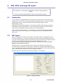
8.2.1
File loading
This shows the four stages of importing the file. Step 1 is to load the DXF file. Clicking the
Load File button displays an open file dialog for this. Figure 8.2 shows a file with two
rectangles and a circle.
Figure 8.2 - a drawing of eight lines and one circle
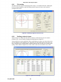
8.2.2
Defining action for layers
The next stage is to define how the lines on each layer of the drawing are to be treated.
Click the Layer Control button to display the dialog shown in figure 8.3.
Turn on the layer or layers which have lines on them that you want to cut, choose the tool to
use, the depth of cut, the feedrate to use, the plunge rate, the spindle speed (only used if you
have a step/direction or PWM spindle controller) and the order in which you want the layers
cutting. Notice that the "Depth of cut" value is the Z value to be used in the cut so, if the
Figure 8.3 - Options for each layer
Using Mach3Mill
8-2
DXF, HPGL and image file import
surface of the work is Z = 0, will be a negative value. The order may be important for issues like
cutting holes out of a piece before it is cut from the surrounding material.
8.2.3
Conversion options
Next you choose the options for the conversion process (see step 3 on figure 8.2).
DXF Information: Gives general details of your file which are useful for diagnostic
purposes.
Optimise: If Optimise is not checked then the entities (lines etc.) will be cut in the order in
which they appear in the DXF file. If it is checked then they will be re-ordered to minimise the
amount of rapid traverse movement required. Note that the cuts are always optimized to
minimize the number of tool changes required.
As Drawn: If As Drawn is not checked then the zero coordinates of the G-code will be the
"bottom left corner" of the drawing. If it is checked then the coordinates of the drawing will be
the coordinates of the G-code produced.
Plasma Mode: If Plasma Mode is checked then M3 and M5 commands will be produced to
turn the arc/laser on and off between cuts. If it is not checked then the spindle will be
started at the beginning of the part program, stopped for tool changes and finally stopped at the
end of the program.
Connection Tol. Two lines on the same layer will be considered to join if the distance
between their ends is less than the value of this control. This means that they will be cut
without a move to the "Rapid Plane" being inserted between them. If the original drawing
was drawn with some sort of "snap" enabled then this feature is probably not required.
Rapid plane: This control defines the Z value to be adopted during rapid moves between
entities in the drawing.
Lathe mode: If Lathe Mode is checked then the horizontal (plus X) direction of the drawing will
be coded as Z in the G-code and the vertical ( plus Y) will be coded as minus X so that a part
outline drawn with the horizontal axis of the drawing as its centerline is displayed and cut
correctly in Mach3Turn.
8.2.4
Generation of G-code
Finally click Generate G-code to perform step 4. It is conventional to save the generated Gcode file with a .TAP extension but this is not required and Mach3 will not insert the
extension automatically.
You can repeat steps 2 to 4, or indeed 1 to 4 and when you have finished these click Done.
Mach3 will load the last G-code file which you have generated. Notice the comments
identifying its name and date of creation.
Notes:
The generated G-code has feedrates depending on the layers imported. Unless your
spindle responds to the S word, you will have to manually set up the spindle speed
and change speeds during tool changes.
DXF input is good for simple shapes as it only requires a basic CAD program to
generate the input file and it works to the full accuracy of your original drawing
DXF is good for defining parts for laser or plasma cutting where the "tool"
diameter is very small
For milling you will have to make your own manual allowances for the diameter of
the cutter. The DXF lines will be the path of the centreline of the cutter. This is
not straightforward when you are cutting complex shapes.
The program generated from a DXF file does not have multiple passes to rough out
a part or clear the centre of a pocket. To achieve these automatically you will need
to use a CAM program
8-3
Using Mach3Mill
DXF, HPGL and image file import
If your DXF file contains "text" then this can be in two forms depending on the
program which generated it. The letters may be a series of lines. These will be
imported into Mach3. The letters may be DXF Text objects. In this case they will
be ignored. Neither of these situations will give you G-code which will engrave
letters in the font used in the original drawing although the lines of an outline font
may be satisfactory with a small v-point or bullnose cutter. A plasma or laser
cutter will have a narrow enough cut to follow the outline of the letters and cut
them out although you have to be sure that the centre of letters like "o" or "a" is
cut before the outline!
8.3
HPGL import
HPGL files contain lines drawn with one or more pens. Mach3Mill makes the same cuts for all
pens. HPGL files can be created by most CAD software and often have the filename extension
.HPL or .PLT.
Figure 8.4 - HPGL import filter
8.3.1
About HPGL
An HPGL file represents objects to a lower precision than DXF and uses straight line
segments to represent all curves even if they are circles.
The import process for HPGL is similar to DXF in that a .TAP file is produced which
contains the G-code produced from the HPGL
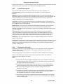
8.3.2
Choosing file to import
The import filter is accessed from File>Import HPGL/BMP/JPG and the HPGL button on the
dialog. Figure 8.4 shows the import dialog itself.
First choose the Scale corresponding to that at which the HPGL file was produced. This is
usually 40 HPGL units per millimetre (1016 units per inch). You can change this to suit
different HPGL formats or to scale your g-code file. For example, choosing 20 (rather than 40)
would double the size of the objects defined.
Now enter the name of the file containing the HPGL data or "Browse" for it. The default
extension for browsing is .PLT so it is convenient to create your files named like this.
Using Mach3Mill
8-4
DXF, HPGL and image file import
8.3.3
Import parameters
The Pen Up control is the Z values (in the current unit in which Mach3 is working) to be
used when making moves. Pen Up will typically need to position the tool just above the
work.
Different depths of cut and feed rates can be programmed for each of the “pens” used to
produce the drawing. You can also define the order in which you want cuts to be made. This
allows cutting the inside of an object before you cut it from the stock!
If Check only for laser table is checked then the G-code will include an M3 (Spindle Start
Clockwise) before the move to the Pen Down Z level and an M5 (Spindle Stop) before the
move to the Pen Up level to control the laser.
8.3.4
Writing the G-code file
Finally, having defined the import translations, click Import File to actually import the data
to Mach3Mill. You will be prompted for the name to use for the file which will store the
generated code. You should type the full name including the extension which you wish to
use or select an existing file to overwrite. Conventionally this extension will be .TAP.
After writing the file click OK to return to Mach3. Your G-Code file will have been loaded.
Notes:
The import filter is run by suspending Mach3 and running the filter program. If
you switch to the Mach3Mill screen (for example by accidentally clicking on it)
then it will appear to have locked up. You can easily continue by using the
Windows task bar to return to the filter and completing the import process. This is
similar to the way the Editor for part programs is run.
If your .TAP file already exists and is open in Mach3, then the import filter will
not be able to write to it. Suppose you have tested an import and want to change
the translations by importing again, then you need to make sure that you close the
.TAP file in Mach3Mill before repeating the import.
It is generally easiest to work in metric units throughout when importing HPGL
files.
If you use the "Laser Table" option with a laser or plasma cutter then you need to
check if the sequence of M3/M5 and the moves in the Z direction is compatible
with initiating and finishing a cut correctly.
For milling you will have to make your own manual allowances for the diameter of
the cutter. The HPGL lines will be the path of the centreline of the cutter. This
allowance is not straightforward to calculate when you are cutting complex
shapes.
The program generated from a HPGL file does not have multiple passes to rough
out a part or clear the centre of a pocket. To achieve these automatically you will
need to use a CAM program
8-5
Using Mach3Mill
DXF, HPGL and image file import
8.4
Bitmap import (BMP & JPEG)
This option allows you to import a
photograph and generate a G-code
program which will render different
shades of grey a different depths of
cut. The result is a photo-realistic
engraving.
8.4.1
Choosing file to
import
The import filter is accessed from
File>Import HPGL/BMP/JPG and
the JPG/BMP button on the dialog.
The first step is to define the file
containing the image using the
Load Image File button. When the
file is loaded a dialog prompts you
for the area on the workpiece into
which the image is to be fitted. You
Figure 8.5 - Size of photographic import
can use inch or metric units as you
wish depending on the G20/21
mode in which you will run the generated part program. Figure 8.5 shows this dialog. The
Maintain Perspective checkbox automatically computes the Y-size if a given X-size is
specified and vice versa so as to preserve the aspect ratio of the original photograph. If the
image is in color it will be converted to monochrome as it is imported.
8.4.2
Choose type of rendering
Next you select
the method of
rendering the
image. This is
defining the path
of the tool as it
"rasterises" the
image. Raster
X/Y cuts along
the X axis
moving the Y
axis at the end of
each X-line.
Raster Y/X
makes the raster
lines be in the Y
direction
incrementing X
for each line.
Spiral starts at
the outside of a
circle bounding
the image and
moves in to the
centre. Each
raster line is
made up of a
series of straight
Using Mach3Mill
Figure 8.6 - Defining the Step-over
8-6
DXF, HPGL and image file import
lines with the height of the Z coordinates of the ends depending on the shade of grey of that part
of the picture.
8.4.3
Raster and spiral rendering
As you select one of these raster methods you will be prompted by a dialog for the stepover values. See figure 8.6. These define the distance between raster lines and the length of the
short segments making up each line. The total number of moves is the XSize X-StepOver x YSizeY-Step-Over and, of course, increases as the square of the size of the object and
the inverse square of the size of step-over. You should start with a modest resolution to avoid
impossibly big files and long cutting times.
8.4.4
Dot diffusion rendering
If you choose the Dot
Diffusion rendering
method then you will
be asked for a
different set of
details. Dot diffusion
"drills" a series of
dots, in a regular
grid, in the work.
Typically these will
be formed by a Vpointed or bull-nosed
tool. The depth of
each dot is
determined by the
shade of grey at the
point on the image.
The number of dots
required to cover the
area is computed by
the filter on the basis
of the shape of the
tool and the depth
(relief) of engraving
you select. Figure 9.7
Figure 9.7 - Dot diffusion parameters
illustrates the data
required. Each dot consists of a move to its location, a Z move to its depth and a Z move to
above the work. You must prepare your image with a suitable photo editor to have a
reasonable number of pixels to control the computation load when diffusing the dots. The
statistics obtained by the Check Stats button will give you an idea of how sensible your
choice of parameters has been.
Now having defined the rendering technique you set the Safe Z at which moves over the
work will be done and choose if black or white is to be the deepest cut.
8.4.5
Writing the G-code file
Finally click Convert to actually import the data into Mach3Mill. You will be prompted for the
name to use for the file which will store the generated code. You should type the full name
including the extension which you wish to use or select an existing file to overwrite.
Conventionally this extension will be .TAP.
Notes:
The import filter is run by suspending Mach3 and running the filter program. If
you switch to the Mach3Mill screen (for example by accidentally clicking on it)
then it will appear to have locked up. You can easily continue by using the
8-7
Using Mach3Mill
DXF, HPGL and image file import
Windows task bar to return to the filter and completing the import process. This is
similar to the way the Editor for part programs is run.
If your .TAP file already exists and is open in Mach3, then the import filter will
not be able to write to it. Suppose you have tested an import and want to change
the translations by importing again, then you need to make sure that you close the
.TAP file in Mach3Mill before repeating the import.
You will need to define the feedrate to be used using MDI or by editing the part
program before it is run.
Dot Diffusion places big demands on the performance of your Z axis. You must set
the Safe Z as low as possible to minimise the distance travelled and have the Z
axis motor tuning very carefully set. Lost steps part of the way through an
engraving will ruin the job!
Using Mach3Mill
8-8
G and M-code reference
9.
Cutter compensation
Cutter compensation is a feature of Mach3 which you many never have to
use. Most CAD/CAM programs can be told the nominal diameter of your
mill and will output part programs which cut the part outline or pocket which
you have drawn by themselves allowing for the tool diameter. Because the
CAD/CAM software has a better overall view of the shapes being cut it may
be able to do a better job than Mach3 can when avoiding gouges at sharp
internal corners.
Having compensation in Mach3 allows you to: (a) use a tool different in
diameter from that programmed (e.g. because it has be reground) or (b) to
use a part program that describes the desired outline rather than the path of
the center of the tool (perhaps one written by hand).
However, as compensation is not trivial, it is described in this chapter
should you need to use it.
This feature is under development and may change significantly in the final
release of Mach3.
9.1
Introduction to compensation
As we have seen Mach3
controls the movement
of the Controlled Point.
In practice no tool
(except perhaps a Vengraver) is a point, so
cuts will be made at a
different place to the
Controlled Point
depending on the radius
of the cutter.
It is generally easiest to
Figure 9.1 - Two possible toolpaths to cut triangle
allow your CAD/CAM
software to take account
of this when cutting out pockets or the outline of shapes.
Mach3 does, however, support calculations to compensate for the diameter (radius) of the
cutter. In industrial applications this is aimed at allowing for a cutter which, through
regrinding, is not exactly the diameter of the tool assumed when the part program was
written. The compensation can be enabled by the machine operator rather than requiring the
production of another part program.
Of the face of it, the problem should be easy to solve. All you need to do is to offset the
controlled point by an appropriate X and Y to allow for the tool radius. Simple trigonometry
gives the distances depending on the angle the direction of cut makes to the axes.
In practice it is not quite so easy. There are several issues but the main one is that the
machine has to set a Z position before it starts cutting and at that time it does not know the
direction in which the tool is going to be moving. This problem is solved by providing "preentry
moves" which take place in waste material of the part. These ensure that the
compensation calculations can be done before the actual part outline is being cut. Choice of a
path which runs smoothly into the part's outline also optimises the surface finish. An exit move
is sometimes used to maintain the finish at the end of a cut.
9-1
Using Mach3Mill
G and M-code Reference
9.2
Two Kinds of Contour
Mach3 handles compensation for two types of contour:
The contour given in the part program code is the edge of material that is not to be
machined away. We will call this type a "material edge contour". This is the sort
of code that might be "hand written"
The contour given in the NC code is the tool path that would be followed by a tool
of exactly the correct radius. We will call this type a "tool path contour". This is
the sort of code that a CAD/CAM program might produce if it is aware of the
intended cutter diameter
The interpreter does not have any setting that determines which type of contour is used, but
the numerical description of the contour will, of course, differ (for the same part geometry)
between the two types and the values for diameters in the tool table will be different for the
two types.
9.2.1
Material Edge Contour
When the contour is the edge of the material, the outline of the edge is described in the part
program. For a material edge contour, the value for the diameter in the tool table is the
actual value of the diameter of the tool. The value in the table must be positive. The NC
code for a material edge contour is the same regardless of the (actual or intended) diameter
of the tool.
Example1:
Here is an NC program which cuts material away from the outside of the triangle in figure
10.1 above. In this example, the cutter compensation radius is the actual radius of the tool in
use, which is 0.5. The value for the diameter in the tool table is twice the radius, which is
1.0.
N0010
N0020
N0030
N0040
N0050
G41 G1 X2 Y2 (turn compensation on and make entry move)
Y-1 (follow right side of triangle)
X-2 (follow bottom side of triangle)
X2 Y2 (follow hypotenuse of triangle)
G40 (turn compensation off)
This will result in the tool following a path consisting of an entry move and the path shown on
the left going clockwise around the triangle. Notice that the coordinates of the triangle of
material appear in the NC code. Notice also that the tool path includes three arcs which are not
explicitly programmed; they are generated automatically.
9.2.2
Tool Path Contour
When the contour is a tool path contour, the path is described in the part program. It is
expected that (except for during the entry moves) the path is intended to create some part
geometry. The path may be generated manually or by a CAD/CAM program, considering the
part geometry which is intended to be made. For Mach3 to work, the tool path must be such
that the tool stays in contact with the edge of the part geometry, as shown on the left side of
figure 10.1. If a path of the sort shown on the right of figure 10.1 is used, in which the tool
does not stay in contact with the part geometry all the time, the interpreter will not be able to
compensate properly when undersized tools are used.
For a tool path contour, the value for the cutter diameter in the tool table will be a small
positive number if the selected tool is slightly oversized and will be a small negative
number if the tool is slightly undersized. As implemented, if a cutter diameter value is
negative, the interpreter compensates on the other side of the contour from the one
programmed and uses the absolute value of the given diameter. If the actual tool is the
correct size, the value in the table should be zero.
Tool Path Contour example:
Suppose the diameter of the cutter currently in the spindle is 0.97, and the diameter
assumed in generating the tool path was 1.0. Then the value in the tool table for the
Using Mach3Mill
9-2
G and M-code reference
diameter for this tool should be -0.03. Here is an NC program which cuts material away
from the outside of the triangle in the figure.
N0010 G1 X1 Y4.5 (make alignment move)
N0020 G41 G1 Y3.5 (turn compensation on and make first entry
move)
N0030 G3 X2 Y2.5 I1 (make second entry move)
N0040 G2 X2.5 Y2 J-0.5 (cut along arc at top of tool path)
N0050 G1 Y-1 (cut along right side of tool path)
N0060 G2 X2 Y-1.5 I-0.5 (cut along arc at bottom right of tool
path)
N0070 G1 X-2 (cut along bottom side of tool path)
N0080 G2 X-2.3 Y-0.6 J0.5 (cut along arc at bottom left of
tool path)
N0090 G1 X1.7 Y2.4 (cut along hypotenuse of tool path)
N0100 G2 X2 Y2.5 I0.3 J-0.4 (cut along arc at top of tool
path)
N0110 G40 (turn compensation off)
This will result in the tool making an alignment move and two entry moves, and then
following a path slightly inside the path shown on the left in figure 10.1 going clockwise
around the triangle. This path is to the right of the programmed path even though G41 was
programmed, because the diameter value is negative.
9.2.3
Programming Entry Moves
In general, an alignment move and an entry moves are needed to begin compensation
correctly. The tool should be at least a diameter away from the finished cut before the entry
move is made.
9-3
Using Mach3Mill
G and M-code Reference
10. Mach 3 G- and M-code language reference
This section defines the language (G-codes etc.) that are understood and
interpreted by Mach3.
Certain functionality which was defined for machines in the NIST NMC
(Next Generation Controller) architecture but is not presently implemented
my Mach3 is given in grey type in this chapter. If this functionality is
important for your application then please let ArtSoft Corporation know your
needs and they will be included in our development planning cycle.
10.1
Some definitions
10.1.1
Linear Axes
The X, Y, and Z axes form a standard right-handed coordinate system of orthogonal linear
axes. Positions of the three linear motion mechanisms are expressed using coordinates on
these axes.
10.1.2
Rotational Axes
The rotational axes are measured in degrees as wrapped linear axes in which the direction
of positive rotation is counterclockwise when viewed from the positive end of the
corresponding X, Y, or Z-axis. By "wrapped linear axis," we mean one on which the
angular position increases without limit (goes towards plus infinity) as the axis turns
counterclockwise and decreases without limit (goes towards minus infinity) as the axis turns
clockwise. Wrapped linear axes are used regardless of whether or not there is a mechanical
limit on rotation.
Clockwise or counterclockwise is from the point of view of the workpiece. If the workpiece is
fastened to a turntable which turns on a rotational axis, a counterclockwise turn from the point
of view of the workpiece is accomplished by turning the turntable in a direction that (for most
common machine configurations) looks clockwise from the point of view of
someone standing next to the machine.
10.1.3
Scaling input
It is possible to set up scaling factors for each axis. These will be applied to the values of X,
Y, Z, A, B, C, I, J and R words whenever these are entered. This allows the size of features
machined to be altered and mirror images to be created - by use of negative scale factors.
The scaling is the first thing done with the values and things like feed rate are always based on
the scaled values.
The offsets stored in tool and fixture tables are not scaled before use. Scaling may, of
course, have been applied at the time the values were entered (say using G10).
10.1.4
Controlled Point
The controlled point is the point whose position and rate of motion are controlled. When the tool
length offset is zero (the default value), this is a point on the spindle axis (often called the gauge
point) that is some fixed distance beyond the end of the spindle, usually near the end of a tool
holder that fits into the spindle. The location of the controlled point can be
moved out along the spindle axis by specifying some positive amount for the tool length
offset. This amount is normally the length of the cutting tool in use, so that the controlled
point is at the end of the cutting tool.
Using Mach3Mill
10-4
G and M-code reference
10.1.5
Co-ordinated Linear Motion
To drive a tool along a specified path, a machining system must often co-ordinate the
motion of several axes. We use the term "co-ordinated linear motion" to describe the
situation in which, nominally, each axis moves at constant speed and all axes move from their
starting positions to their end positions at the same time. If only the X, Y, and Z axes (or any
one or two of them) move, this produces motion in a straight line, hence the word "linear" in the
term. In actual motions, it is often not possible to maintain constant speed because acceleration
or deceleration is required at the beginning and/or end of the motion. It is feasible, however, to
control the axes so that, at all times, each axis has completed the same fraction of its required
motion as the other axes. This moves the tool along the same path, and we also call this kind of
motion co-ordinated linear motion.
Co-ordinated linear motion can be performed either at the prevailing feed rate, or at rapid
traverse rate. If physical limits on axis speed make the desired rate unobtainable, all axes are
slowed to maintain the desired path.
10.1.6
Feed Rate
The rate at which the controlled point or the axes move is nominally a steady rate which
may be set by the user. In the Interpreter, the interpretation of the feed rate is as follows
unless inverse time feed rate (G93) mode is being used:
For motion involving one or more of the linear axes (X, Y, Z and optionally A, B,
C), without simultaneous rotational axis motion, the feed rate means length units per
minute along the programmed linear XYZ(ABC) path
For motion involving one or more of the linear axes (X, Y, Z and optionally A, B,
C), with simultaneous rotational axis motion, the feed rate means length units per
minute along the programmed linear XYZ(ABC) path combined with the angular
velocity of the rotary axes multiplied by the appropriate axis Correction Diameter
multiplied by pi (i.e. the declared "circumference" of the part
For motion of one rotational axis with X, Y, and Z axes not moving, the feed rate
means degrees per minute rotation of the rotational axis.
For motion of two or three rotational axes with X, Y, and Z axes not moving, the
rate is applied as follows. Let dA, dB, and dC be the angles in degrees through which
the A, B, and C axes, respectively, must move. Let D = sqrt (dA2 + dB2 + dC2).
Conceptually, D is a measure of total angular motion, using the usual Euclidean metric.
Let T be the amount of time required to move through D degrees at the current feed rate
in degrees per minute. The rotational axes should be moved in co-ordinated linear
motion so that the elapsed time from the start to the end of the motion is T plus any
time required for acceleration or deceleration.
10.1.7
Arc Motion
Any pair of the linear axes (XY, YZ, XZ) can be controlled to move in a circular arc in the
plane of that pair of axes. While this is occurring, the third linear axis and the rotational axes
can be controlled to move simultaneously at effectively a constant rate. As in coordinated linear motion, the motions can be co-ordinated so that acceleration and
deceleration do not affect the path.
If the rotational axes do not move, but the third linear axis does move, the trajectory of the
controlled point is a helix.
The feed rate during arc motion is as described in Feed Rate above. In the case of helical
motion, the rate is applied along the helix. Beware as other interpretations are used on other
systems.
10.1.8
Coolant
Flood coolant and mist coolant may each be turned on independently. They are turned off
together.
10-5
Using Mach3Mill
G and M-code Reference
10.1.9
Dwell
A machining system may be commanded to dwell (i.e., keep all axes unmoving) for a
specific amount of time. The most common use of dwell is to break and clear chips or for a
spindle to get up to speed. The units in which you specify Dwell are either seconds or
Milliseconds depending on the setting on Configure>Logic
10.1.10
Units
Units used for distances along the X, Y, and Z axes may be measured in millimetres or
inches. Units for all other quantities involved in machine control cannot be changed.
Different quantities use different specific units. Spindle speed is measured in revolutions
per minute. The positions of rotational axes are measured in degrees. Feed rates are
expressed in current length units per minute or in degrees per minute, as described above.
Warning: We advise you to check very carefully the system's response to changing units while
tool and fixture offsets are loaded into the tables, while these offsets are active and/or while a
part program is excecuting
10.1.11
Current Position
The controlled point is always at some location called the "current position" and Mach3
always knows where that is. The numbers representing the current position are adjusted in the
absence of any axis motion if any of several events take place:
Length units are changed (but see Warning above)
Tool length offset is changed
Coordinate system offsets are changed.
10.1.12
Selected Plane
There is always a "selected plane", which must be the XY-plane, the YZ-plane, or the XZplane
of the machining system. The Z-axis is, of course, perpendicular to the XY-plane, the X-axis to
the YZ-plane, and the Y-axis to the XZ-plane.
10.1.13
Tool Table
Zero or one tool is assigned to each slot in the tool table.
10.1.14
Tool Change
Mach3 allows you to implement a procedure for implementing automatic tool changes
using macros or to change the tools by hand when required.
10.1.15
Pallet Shuttle
Mach3 allows you to implement a procedure for implementing pallet shuttle using macros.
10.1.16
Path Control Modes
The machining system may be put into any one of two path control modes: (1) exact stop
mode, (2) constant velocity mode. In exact stop mode, the machine stops briefly at the end of
each programmed move. In constant velocity mode, sharp corners of the path may be rounded
slightly so that the feed rate may be kept up. These modes are to allow the user to control the
compromise involved in turning corners because a real machine has a finite acceleration due to
the inertia of its mechanism.
Exact stop does what it says. The machine will come to rest at each change of direction and the
tool will therefore precisely follow the commanded path.
Constant velocity will overlap acceleration in the new direction with deceleration in the
current one in order to keep the commanded feedrate. This implies a rounding of any corner
but faster and smoother cutting. This is particularly important in routing and plasma cutting.
Using Mach3Mill
10-6
G and M-code reference
The lower the acceleration of the machine axes, the greater will be the radius of the rounded
corner.
In Plasma mode (set on Configure Logic dialog) the system attempts to optimize corner
motion for plasma cutting by a proprietary algorithm.
It is also possible to define a limiting angle so that changes in direction of more than this angle
will always be treated as Exact Stop even though Constant Velocity is selected. This allows
gentle corners to be smoother but avoids excessive rounding of sharp corners even on
machines with low acceleration on one or more axes. This feature is enabled in the
Configure Logic dialog and the limiting angle is set by a DRO. This setting will probably need
to be chosen experimentally depending on the characteristics of the machine tool and, perhaps,
the toolpath of an individual job.
10.2
Interpreter Interaction with controls
10.2.1
Feed and Speed Override controls
Mach3 commands which enable (M48) or disable (M49) the feed and speed override
switches. It is useful to be able to override these switches for some machining operations. The
idea is that optimal settings have been included in the program, and the operator should not
change them.
10.2.2
Block Delete control
If the block delete control is ON, lines of code which start with a slash (the block delete
character) are not executed. If the switch is off, such lines are executed.
10.2.3
Optional Program Stop control
The optional program stop control (see Configure>Logic) works as follows. If this control
is ON and an input line contains an M1 code, program execution is stopped at the end on
the commands on that line until the Cycle Start button is pushed.
10.3
Tool File
Mach3 maintains a tool file for each of the 254 tools which can be used.
Each data line of the file contains the data for one tool. This allows the definition of the tool
length (Z axis), tool diameter (for milling) and tool tip radius (for turning)
10.4
The language of part programs
10.4.1
Overview
The language is based on lines of code. Each line (also called a "block") may include
commands to the machining system to do several different things. Lines of code may be
collected in a file to make a program.
A typical line of code consists of an optional line number at the beginning followed by one or
more "words." A word consists of a letter followed by a number (or something that
evaluates to a number). A word may either give a command or provide an argument to a
command. For example, G1 X3 is a valid line of code with two words. "G1" is a command
meaning "move in a straight line at the programmed feed rate," and "X3" provides an
argument value (the value of X should be 3 at the end of the move). Most commands start
with either G or M (for General and Miscellaneous). The words for these commands are
called "G codes" and "M codes."
The language has two commands (M2 or M30), either of which ends a program. A program
may end before the end of a file. Lines of a file that occur after the end of a program are not to
be executed in the normal flow so will generally be parts of subroutines.
10-7
Using Mach3Mill
G and M-code Reference
Parameter
number
5161
5162
5163
5164
5165
5166
5181
5182
5183
5184
5185
5186
5191
5192
5193
5194
5195
5196
5211
5212
5213
5214
5215
5216
5220
5221
5222
5223
5224
5225
5226
5241
5242
5243
5244
5245
5246
Meaning
G28 home X
G28 home Y
G28 home Z
G28 home A
G28 home B
G28 home C
G30 home X
G30 home Y
G30 home Z
G30 home A
G30 home B
G30 home C
Scale X
Scale Y
Scale Z
Scale A
Scale B
Scale C
G92 offset X
G92 offset Y
G92 offset Z
G92 offset A
G92 offset B
G92 offset C
Current Work offset
number
Work offset 1 X
Work offset 1 Y
Work offset 1 Z
Work offset 1 A
Work offset 1 B
Work offset 1 C
Work offset 2 X
Work offset 2 Y
Work offset 2 Z
Work offset 2 A
Work offset 2 B
Work offset 2 C
Parameter
number
5261
5262
5263
5264
5265
5266
5281
5282
5283
5284
5285
5286
5301
5302
5303
5304
5305
5306
5321
5322
5323
5324
5325
5326
Meaning
Work offset 3 X
Work offset 3 Y
Work offset 3 Z
Work offset 3 A
Work offset 3 B
Work offset 3 C
Work offset 4 X
Work offset 4 Y
Work offset 4 Z
Work offset 4 A
Work offset 4 B
Work offset 4 C
Work offset 5 X
Work offset 5 Y
Work offset 5 Z
Work offset 5 A
Work offset 5 B
Work offset 5 C
Work offset 6 X
Work offset 6 Y
Work offset 6 Z
Work offset 6 A
Work offset 6 B
Work offset 6 C
And so on every 20
values until
10281
10282
10283
10284
10285
10286
10301
10302
10303
10304
10305
10306
Work offset 254 X
Work offset 254 Y
Work offset 254 Z
Work offset 254 A
Work offset 254 B
Work offset 254 C
Work offset 255 X
Work offset 255 Y
Work offset 255 Z
Work offset 255 A
Work offset 255 B
Work offset 255 C
Figure 10.1 - System defined parameters
10.4.2
Parameters
A Mach3 machining system maintains an array of 10,320 numerical parameters. Many of
them have specific uses. The parameter which are associated with fixtures are persistent
over time. Other parameters will be undefined when Mach3 is loaded. The parameters are
preserved when the interpreter is reset. The parameters with meanings defined by Mach3 are
given in figure 10.1
Using Mach3Mill
10-8
G and M-code reference
10.4.3
Coordinate Systems
The machining system has an absolute coordinate system and 254 work offset (fixture)
systems.
You can set the offsets of tools by G10 L1 P~ X~ Z~. The P word defines the tool
offset number to be set.
You can set the offsets of the fixture systems using G10 L2 P~ X~ Y~ Z~ A~ B~ C~
The P word defines the fixture to be set. The X, Y, Z etc words are the coordinates for the origin
of for the axes in terms of the absolute coordinate system.
You can select one of the first seven work offsets by using G54, G55, G56, G57, G58, G59.
Any of the 255 work offsets can be selected by G59 P~ (e.g. G59 P23 would select
fixture 23). The absolute coordinate system can be selected by G59 P0.
You can offset the current coordinate system using G92 or G92.3. This offset will then
applied on top of work offset coordinate systems. This offset may be cancelled with G92.1
Letter
A
B
C
D
F
G
H
I
J
K
L
M
N
O
P
Q
R
S
T
U
V
W
X
Y
Z
Meaning
A-axis of machine
B-axis of machine
C-axis of machine
tool radius compensation number
feedrate
general function (see Table 5)
tool length offset index
X-axis offset for arcs
X offset in G87 canned cycle
Y-axis offset for arcs
Y offset in G87 canned cycle
Z-axis offset for arcs
Z offset in G87 canned cycle
number of repetitions in canned
cycles/subroutines
key used with G10
miscellaneous function (see Table 7)
line number
Subroutine label number
dwell time in canned cycles
dwell time with G4
key used with G10
feed increment in G83 canned cycle
repetitions of subroutine call
arc radius
canned cycle retract level
spindle speed
tool selection
Synonymous with A
Synonymous with B
Synonymous with C
X-axis of machine
Y-axis of machine
Z-axis of machine
Figure 10.2 - Word initial letters
10-9
Using Mach3Mill
G and M-code Reference
or G92.2.
You can make straight moves in the absolute machine coordinate system by using G53 with
either G0 or G1.
10.5
Format of a Line
A permissible line of input code consists of the following, in order, with the restriction that
there is a maximum (currently 256) to the number of characters allowed on a line.
an optional block delete character, which is a slash "/" .
an optional line number.
any number of words, parameter settings, and comments.
an end of line marker (carriage return or line feed or both).
Any input not explicitly allowed is illegal and will cause the Interpreter to signal an error or to
ignore the line.
Spaces and tabs are allowed anywhere on a line of code and do not change the meaning of the
line, except inside comments. This makes some strange-looking input legal. For
example, the line g0x +0. 12 34y 7 is equivalent to g0 x+0.1234 y7
Blank lines are allowed in the input. They will be ignored.
Input is case insensitive, except in comments, i.e., any letter outside a comment may be in
upper or lower case without changing the meaning of a line.
10.5.1
Line Number
A line number is the letter N followed by an integer (with no sign) between 0 and 99999
written with no more than five digits (000009 is not OK, for example). Line numbers may be
repeated or used out of order, although normal practice is to avoid such usage. A line
number is not required to be used (and this omission is common) but it must be in the
proper place if it is used.
10.5.2
Subroutine labels
A subroutine label is the letter O followed by an integer (with no sign) between 0 and
99999 written with no more than five digits (000009 is not permitted, for example).
Subroutine labels may be used in any order but must be unique in a program although
violation of this rule may not be flagged as an error. Nothing else except a comment should
appear on the same line after a subroutine label.
10.5.3
Word
A word is a letter other than N or O followed by a real value.
Words may begin with any of the letters shown in figure 11.2. The table includes N and O for
completeness, even though, as defined above, line numbers are not words. Several letters (I, J,
K, L, P, R) may have different meanings in different contexts.
A real value is some collection of characters that can be processed to come up with a
number. A real value may be an explicit number (such as 341 or -0.8807), a parameter
value, an expression, or a unary operation value. Definitions of these follow immediately.
Processing characters to come up with a number is called "evaluating". An explicit number
evaluates to itself.
10.5.3.1 Number
The following rules are used for (explicit) numbers. In these rules a digit is a single
character between 0 and 9.
A number consists of (1) an optional plus or minus sign, followed by (2) zero to
many digits, followed, possibly, by (3) one decimal point, followed by (4) zero to
many digits - provided that there is at least one digit somewhere in the number.
Using Mach3Mill
10-10
G and M-code reference
There are two kinds of numbers: integers and decimals. An integer does not have a
decimal point in it; a decimal does.
Numbers may have any number of digits, subject to the limitation on line length.
Only about seventeen significant figures will be retained, however (enough for all
known applications).
A non-zero number with no sign as the first character is assumed to be positive.
Notice that initial (before the decimal point and the first non-zero digit) and trailing (after
the decimal point and the last non-zero digit) zeros are allowed but not required. A number
written with initial or trailing zeros will have the same value when it is read as if the extra
zeros were not there.
Numbers used for specific purposes by Mach3 are often restricted to some finite set of
values or some to some range of values. In many uses, decimal numbers must be close to
integers; this includes the values of indexes (for parameters and carousel slot numbers, for
example), M codes, and G codes multiplied by ten. A decimal number which is supposed be
close to an integer is considered close enough if it is within 0.0001 of an integer.
10.5.3.2 Parameter Value
A parameter value is the hash character # followed by a real value. The real value must
evaluate to an integer between 1 and 10320. The integer is a parameter number, and the
value of the parameter value is whatever number is stored in the numbered parameter.
The # character takes precedence over other operations, so that, for example, #1+2 means
the number found by adding 2 to the value of parameter 1, not the value found in parameter
3. Of course, #[1+2] does mean the value found in parameter 3. The # character may be
repeated; for example ##2 means the value of the parameter whose index is the (integer)
value of parameter 2.
10.5.3.3 Expressions and Binary Operations
An expression is a set of characters starting with a left bracket [ and ending with a
balancing right bracket ]. In between the brackets are numbers, parameter values,
mathematical operations, and other expressions. An expression may be evaluated to
produce a number. The expressions on a line are evaluated when the line is read, before
anything on the line is executed. An example of an expression is:
[1+acos[0]-[#3**[4.0/2]]]
Binary operations appear only inside expressions. Nine binary operations are defined. There are
four basic mathematical operations: addition (+), subtraction (-), multiplication (*), and
division (/). There are three logical operations: non-exclusive or (OR), exclusive or (XOR),
and logical and (AND). The eighth operation is the modulus operation (MOD). The ninth
operation is the "power" operation (**) of raising the number on the left of the operation to
the power on the right.
The binary operations are divided into three groups. The first group is: power. The second
group is: multiplication, division, and modulus. The third group is: addition, subtraction,
logical non-exclusive or, logical exclusive or, and logical and. If operations are strung
together (for example in the expression [2.0/3*1.5-5.5/11.0]), operations in the first
group are to be performed before operations in the second group and operations in the second
group before operations in the third group. If an expression contains more than one operation
from the same group (such as the first / and * in the example), the operation on the left is
performed first. Thus, the example is equivalent to: [((2.0/3)*1.5)(5.5/11.0)] which simplifies to [1.0-0.5] which is 0.5.
The logical operations and modulus are to be performed on any real numbers, not just on
integers. The number zero is equivalent to logical false, and any non-zero number is
equivalent to logical true.
10-11
Using Mach3Mill
G and M-code Reference
10.5.3.4 Unary Operation Value
A unary operation value is either "ATAN" followed by one expression divided by another
expression (for example ATAN[2]/[1+3]) or any other unary operation name followed
by an expression (for example SIN[90]). The unary operations are: ABS (absolute value),
ACOS (arc cosine), ASIN (arc sine), ATAN (arc tangent), COS (cosine), EXP (e raised to
the given power), FIX (round down), FUP (round up), LN (natural logarithm), ROUND
(round to the nearest whole number), SIN (sine), SQRT (square root), and TAN (tangent).
Arguments to unary operations which take angle measures (COS, SIN, and TAN) are in
degrees. Values returned by unary operations which return angle measures (ACOS, ASIN,
and ATAN) are also in degrees.
The FIX operation rounds towards the left (less positive or more negative) on a number
line, so that FIX[2.8]=2 and FIX[-2.8]=-3, for example. The FUP operation rounds
towards the right (more positive or less negative) on a number line; FUP[2.8]=3 and FUP[2.8]=-2, for example.
10.5.4
Parameter Setting
A parameter setting is the following four items one after the other:
a pound character #
a real value which evaluates to an integer between 1 and 10320,
an equal sign = , and
a real value. For example "#3 = 15" is a parameter setting meaning "set parameter
3 to 15."
A parameter setting does not take effect until after all parameter values on the same line
have been found. For example, if parameter 3 has been previously set to 15 and the line
#3=6 G1 x#3 is interpreted, a straight move to a point where x equals 15 will occur and the
value of parameter 3 will be 6.
10.5.5
Comments and Messages
A line that starts with the percent character, %, is treated as a comment and not interpreted in
any way.
Printable characters and white space inside parentheses is a comment. A left parenthesis always
starts a comment. The comment ends at the first right parenthesis found thereafter. Once a left
parenthesis is placed on a line, a matching right parenthesis must appear before the end of the
line. Comments may not be nested; it is an error if a left parenthesis is found after the start of a
comment and before the end of the comment. Here is an example of a line containing a comment:
G80 M5 (stop motion)
An alternative form of comment is to use the two characters // The remainder of the line is
treated as a comment.
Comments do not cause the machining system to do anything.
A comment contains a message if “MSG,” appears after the left parenthesis and before any
other printing characters. Variants of MSG, which include white space and lower case
characters are allowed. Note that the comma is required. The rest of the characters before the
right parenthesis are considered to be a message to the operator. Messages are displayed on
screen in the "Error" intelligent label.
10.5.6
Item Repeats
A line may have any number of G words, but two G words from the same modal group may not
appear on the same line.
A line may have zero to four M words. Two M words from the same modal group may not
appear on the same line.
For all other legal letters, a line may have only one word beginning with that letter.
Using Mach3Mill
10-12
G and M-code reference
If a parameter setting of the same parameter is repeated on a line, #3=15 #3=6, for
example, only the last setting will take effect. It is silly, but not illegal, to set the same
parameter twice on the same line.
If more than one comment appears on a line, only the last one will be used; each of the
other comments will be read and its format will be checked, but it will be ignored thereafter. It is
expected that putting more than one comment on a line will be very rare.
10.5.7
Item order
The three types of item whose order may vary on a line (as given at the beginning of this
section) are word, parameter setting, and comment. Imagine that these three types of item are
divided into three groups by type.
The first group (the words) may be reordered in any way without changing the meaning of the
line.
If the second group (the parameter settings) is reordered, there will be no change in the
meaning of the line unless the same parameter is set more than once. In this case, only the
last setting of the parameter will take effect. For example, after the line #3=15 #3=6 has
been interpreted, the value of parameter 3 will be 6. If the order is reversed to #3=6
#3=15 and the line is interpreted, the value of parameter 3 will be 15.
If the third group (the comments) contains more than one comment and is reordered, only the
last comment will be used.
If each group is kept in order or reordered without changing the meaning of the line, then
the three groups may be interleaved in any way without changing the meaning of the line.
For example, the line g40 g1 #3=15 (so there!) #4=-7.0 has five items and
means exactly the same thing in any of the 120 possible orders - such as #4=-7.0 g1
#3=15 g40 (so there!)- for the five items.
10.5.8
Commands and Machine Modes
Mach3 has many commands which cause a machining system to change from one mode to
another, and the mode stays active until some other command changes it implicitly or
explicitly. Such commands are called "modal". For example, if coolant is turned on, it stays on
until it is explicitly turned off. The G codes for motion are also modal. If a G1 (straight move)
command is given on one line, for example, it will be executed again on the next line if one or
more axis words is available on the line, unless an explicit command is given on that next line
using the axis words or cancelling motion.
"Non-modal" codes have effect only on the lines on which they occur. For example, G4
(dwell) is non-modal.
10.6
Modal Groups
Modal commands are arranged in sets called "modal groups", and only one member of a
modal group may be in force at any given time. In general, a modal group contains
commands for which it is logically impossible for two members to be in effect at the same
time - like measure in inches vs. measure in millimetres. A machining system may be in many
modes at the same time, with one mode from each modal group being in effect. The modal
groups are shown in figure 10.3.
10-13
Using Mach3Mill
G and M-code Reference
The modal Groups for G codes are
group 1 = {G00, G01, G02, G03, G38.2, G80, G81, G82, G84, G85,
G86, G87, G88, G89} motion
group 2 = {G17, G18, G19} plane selection
group 3 = {G90, G91} distance mode
group 5 = {G93, G94} feed rate mode
group 6 = {G20, G21} units
group 7 = {G40, G41, G42} cutter radius compensation
group 8 = {G43, G49} tool length offset
group 10 = {G98, G99} return mode in canned cycles
group 12 = {G54, G55, G56, G57, G58, G59, G59.xxx} coordinate
system selection
group 13 = {G61, G61.1, G64} path control mode
The modal groups for M codes are:
group 4 = {M0, M1, M2, M30} stopping
group 6 = {M6} tool change
group 7 = {M3, M4, M5} spindle turning
group 8 = {M7, M8, M9} coolant (special case: M7 and M8 may be
active at the same time)
group 9 = {M48, M49} enable/disable feed and speed override controls
In addition to the above modal groups, there is a group for non-modal G
codes:
group 0 = {G4, G10, G28, G30, G53, G92, G92.1, G92.2, G92.3}
Figure 10.3 - Modal groups
For several modal groups, when a machining system is ready to accept commands, one
member of the group must be in effect. There are default settings for these modal groups.
When the machining system is turned on or otherwise re-initialized, the default values are
automatically in effect.
Group 1, the first group on the table, is a group of G codes for motion. One of these is
always in effect. That one is called the current motion mode.
It is an error to put a G-code from group 1 and a G-code from group 0 on the same line if both
of them use axis words. If an axis word-using G-code from group 1 is implicitly in effect on a
line (by having been activated on an earlier line), and a group 0 G-code that uses axis words
appears on the line, the activity of the group 1 G-code is suspended for that line. The axis wordusing G-codes from group 0 are G10, G28, G30, and G92.
Mach3 displays the current mode at the top of each screen.
10.7
G Codes
G codes of the Mach3 input language are shown in figure 10.4 and are the described in
detail.
The descriptions contain command prototypes, set in courier type.
In the command prototypes, the tilde (~) stand for a real value. As described earlier, a real
value may be (1) an explicit number, 4.4, for example, (2) an expression, [2+2.4], for
example, (3) a parameter value, #88, for example, or (4) a unary function value, acos[0], for
example.
In most cases, if axis words (any or all of X~, Y~, Z~, A~, B~, C~, U~, V~,
W~) are given, they specify a destination point. Axis numbers relate to the currently active
coordinate system, unless explicitly described as being in the absolute coordinate system.
Where axis words are optional, any omitted axes will have their current value. Any items in
Using Mach3Mill
10-14
G and M-code reference
G0
G1
G2
G3
G4
G10
G12
G13
G15/G16
G17
G18
G19
G20/G21
G28
G28.1
G30
G31
G40
G41/G42
G43
G49
G50
G51
G52
G53
G54
G55
G56
G57
G58
G59
G61/G64
G68/G69
G70/G71
G73
G80
G81
G82
G83
G84
G85/G86/G
88/G89
G90
G91
G92
G92.x
G93
G94
G95
G98
G99
Summary of G-codes
Rapid positioning
Linear interpolation
Clockwise circular/helical interpolation
Counterclockwise circular/Helical interpolation
Dwell
Coordinate system origin setting
Clockwise circular pocket
Counterclockwise circular pocket
Polar Coordinate moves in G0 and G1
XY Plane select
XZ plane select
YZ plane select
Inch/Millimetre unit
Return home
Reference axes
Return home
Straight probe
Cancel cutter radius compensation
Start cutter radius compensation left/right
Apply tool length offset (plus)
Cancel tool length offset
Reset all scale factors to 1.0
Set axis data input scale factors
Temporary coordinate system offsets
Move in absolute machine coordinate system
Use fixture offset 1
Use fixture offset 2
Use fixture offset 3
Use fixture offset 4
Use fixture offset 5
Use fixture offset 6 / use general fixture number
Exact stop/Constant Velocity mode
Rotate program coordinate system
Inch/Millimetre unit
Canned cycle - peck drilling
Cancel motion mode (including canned cycles)
Canned cycle - drilling
Canned cycle - drilling with dwell
Canned cycle - peck drilling
Canned cycle - right hand rigid tapping
Canned cycle - boring
Absolute distance mode
Incremental distance mode
Offset coordinates and set parameters
Cancel G92 etc.
Inverse time feed mode
Feed per minute mode
Feed per rev mode
Initial level return after canned cycles
R-point level return after canned cycles
Figure 10.4 - Table of G codes
the command prototypes not explicitly described as optional are required. It is an error if a
required item is omitted.
10-15
Using Mach3Mill
G and M-code Reference
U, V and W are synonyms for A, B and C. Use of A with U, B with V etc. is erroneous (like
using A twice on a line). In the detailed descriptions of codes U, V and W are not explicitly
mentioned each time but are implied by A, B or C.
In the prototypes, the values following letters are often given as explicit numbers. Unless
stated otherwise, the explicit numbers can be real values. For example, G10 L2 could equally
well be written G[2*5] L[1+1]. If the value of parameter 100 were 2,
G10 L#100 would also mean the same. Using real values which are not explicit numbers as
just shown in the examples is rarely useful.
If L~ is written in a prototype the "~" will often be referred to as the "L number". Similarly the
"~" in H~ may be called the "H number", and so on for any other letter.
If a scale factor is applied to any axis then it will be applied to the value of the
corresponding X, Y, Z, A/U, B/V, C/W word and to the relevant I, J, K or R words when
they are used.
10.7.1
Rapid Linear Motion - G0
(a) For rapid linear motion, program G0 X~ Y~ Z~ A~ B~ C~, where all the axis
words are optional, except that at least one must be used. The G0 is optional if the current
motion mode is G0. This will produce co-ordinated linear motion to the destination point at the
current traverse rate (or slower if the machine will not go that fast). It is expected that cutting
will not take place when a G0 command is executing.
(b) If G16 has been executed to set a Polar Origin then for rapid linear motion to a point
described by a radius and angle G0 X~ Y~ can be used. X~ is the radius of the line from
the G16 polar origin and Y~ is the angle in degrees measured with increasing values
counterclockwise from the 3 o'clock direction (i.e. the conventional four quadrant
conventions).
Coordinates of the current point at the time of executing the G16 are the polar origin. It is
an error if:
all axis words are omitted.
If cutter radius compensation is active, the motion will differ from the above; see Cutter
Compensation. If G53 is programmed on the same line, the motion will also differ; see
Absolute Coordinates.
10.7.2
Linear Motion at Feed Rate - G1
(a) For linear motion at feed rate (for cutting or not), program G1 X~ Y~ Z~ A~ B~
C~, where all the axis words are optional, except that at least one must be used. The G1 is
optional if the current motion mode is G1. This will produce co-ordinated linear motion to
the destination point at the current feed rate (or slower if the machine will not go that fast).
(b) If G16 has been executed to set a polar origin then linear motion at feed rate to a point
described by a radius and angle G0 X~ Y~ can be used. X~ is the radius of the line from
the G16 polar origin and Y~ is the angle in degrees measured with increasing values
counterclockwise from the 3 o'clock direction (i.e. the conventional four quadrant
conventions).
Coordinates of the current point at the time of executing the G16 are the polar origin. It is
an error if:
all axis words are omitted.
If cutter radius compensation is active, the motion will differ from the above; see Cutter
Compensation. If G53 is programmed on the same line, the motion will also differ; see
Absolute Coordinates.
Using Mach3Mill
10-16
G and M-code reference
10.7.3
Arc at Feed Rate - G2 and G3
A circular or helical arc is specified using either G2 (clockwise arc) or G3
(counterclockwise arc). The axis of the circle or helix must be parallel to the X, Y, or Z-axis of
the machine coordinate system. The axis (or, equivalently, the plane perpendicular to the axis) is
selected with G17 (Z-axis, XY-plane), G18 (Y-axis, XZ-plane), or G19 (X-axis, YZ-plane). If
the arc is circular, it lies in a plane parallel to the selected plane.
If a line of code makes an arc and includes rotational axis motion, the rotational axes turn at a
constant rate so that the rotational motion starts and finishes when the XYZ motion starts and
finishes. Lines of this sort are hardly ever programmed.
If cutter radius compensation is active, the motion will differ from the above; see Cutter
Compensation.
Two formats are allowed for specifying an arc. We will call these the center format and the
radius format. In both formats the G2 or G3 is optional if it is the current motion mode.
10.7.3.1 Radius Format Arc
In the radius format, the coordinates of the end point of the arc in the selected plane are
specified along with the radius of the arc. Program G2 X~ Y~ Z~ A~ B~ C~ R~ (or
use G3 instead of G2). R is the radius. The axis words are all optional except that at least
one of the two words for the axes in the selected plane must be used. The R number is the
radius. A positive radius indicates that the arc turns through 180 degrees or less, while a
negative radius indicates a turn of 180 degrees to 359.999 degrees. If the arc is helical, the
value of the end point of the arc on the coordinate axis parallel to the axis of the helix is
also specified.
It is an error if:
both of the axis words for the axes of the selected plane are omitted,
the end point of the arc is the same as the current point.
It is not good practice to program radius format arcs that are nearly full circles or are
semicircles (or nearly semicircles) because a small change in the location of the end point
will produce a much larger change in the location of the center of the circle (and, hence, the
middle of the arc). The magnification effect is large enough that rounding error in a number
can produce out-of-tolerance cuts. Nearly full circles are outrageously bad, semicircles (and
nearly so) are only very bad. Other size arcs (in the range tiny to 165 degrees or 195 to 345
degrees) are OK.
Here is an example of a radius format command to mill an arc: G17
G2 x
10 y
15 r
20 z
5.
That means to make a clockwise (as viewed from the positive Z-axis) circular or helical arc
whose axis is parallel to the Z-axis, ending where X=10, Y=15, and Z=5, with a radius of
20. If the starting value of Z is 5, this is an arc of a circle parallel to the XY-plane;
otherwise it is a helical arc.
10.7.3.2 Center Format Arc
In the center format, the coordinates of the end point of the arc in the selected plane are
specified along with the offsets of the center of the arc from the current location. In this
format, it is OK if the end point of the arc is the same as the current point. It is an error if:
when the arc is projected on the selected plane, the distance from the current point
to the center differs from the distance from the end point to the center by more
than 0.0002 inch (if inches are being used) or 0.002 millimetre (if millimetres are
being used).
The center is specified using the I and J words. There are two ways of interpreting them.
The usual way is that I and J are the center relative to the current point at the start of the arc.
This is sometimes called Incremental IJ mode. The second way is that I and J specify the
center as actual coordinates in the current system. This is rather misleadingly called
Absolute IJ mode. The IJ mode is set using the Configure>State… menu when Mach3 is set
10-17
Using Mach3Mill
G and M-code Reference
up. The choice of modes are to provide compatibility with commercial controllers. You will
probably find Incremental to be best. In Absolute it will, of course usually be necessary to use
both I and J words unless by chance the arc's centre is at the origin.
When the XY-plane is selected, program G2 X~ Y~ Z~ A~ B~ C~ I~ J~ (or use G3
instead of G2). The axis words are all optional except that at least one of X and Y must be
used. I and J are the offsets from the current location or coordinates - depending on IJ mode (X
and Y directions, respectively) of the center of the circle. I and J are optional except that at
least one of the two must be used. It is an error if:
X and Y are both omitted,
I and J are both omitted.
When the XZ-plane is selected, program G2 X~ Y~ Z~ A~ B~ C~ I~ K~ (or use G3
instead of G2). The axis words are all optional except that at least one of X and Z must be used. I
and K are the offsets from the current location or coordinates - depending on IJ
mode (X and Z directions, respectively) of the center of the circle. I and K are optional
except that at least one of the two must be used. It is an error if:
X and Z are both omitted,
I and K are both omitted.
When the YZ-plane is selected, program G2 X~ Y~ Z~ A~ B~ C~ J~ K~ (or use G3
instead of G2). The axis words are all optional except that at least one of Y and Z must be used. J
and K are the offsets from the current location or coordinates - depending on IJ
mode (Y and Z directions, respectively) of the center of the circle. J and K are optional
except that at least one of the two must be used. It is an error if:
Y and Z are both omitted,
J and K are both omitted.
Here is an example of a center format command to mill an arc in Incremental IJ mode:
G17 G2 x10 y16 i3 j4 z9
That means to make a clockwise (as viewed from the positive z-axis) circular or helical arc
whose axis is parallel to the Z-axis, ending where X=10, Y=16, and Z=9, with its center offset
in the X direction by 3 units from the current X location and offset in the Y direction by 4 units
from the current Y location. If the current location has X=7, Y=7 at the outset, the center will
be at X=10, Y=11. If the starting value of Z is 9, this is a circular arc;
otherwise it is a helical arc. The radius of this arc would be 5.
The above arc in Absolute IJ mode would be:
G17 G2 x10 y16 i10 j11 z9
In the center format, the radius of the arc is not specified, but it may be found easily as the
distance from the center of the circle to either the current point or the end point of the arc.
10.7.4
Dwell - G4
For a dwell, program G4 P~ . This will keep the axes unmoving for the period of time in
seconds or milliseconds specified by the P number. The time unit to be used is set up on the
Config>Logic dialog. For example, with units set to Seconds, G4 P0.5 will dwell for half a
second. It is an error if:
the P number is negative.
10.7.5
Set Coordinate System Data Tool and work offset tables - G10
See details of tool and work offsets for further information on coordinate systems
To set the offset values of a tool, program
G10 L1 P~ X~ Z~ A~, where the P number must evaluate to an integer in the range 0 to
255 - the tool number - Offsets of the tool specified by the P number are reset to the given. The
A number will reset the tool tip radius. Only those values for which an axis word is included on
the line will be reset. The Tool diameter cannot be set in this way.
Using Mach3Mill
10-18
G and M-code reference
To set the coordinate values for the origin of a fixture coordinate system, program
G10 L2 P~ X~ Y~ Z~ A~ B~ C~, where the P number must evaluate to an integer in
the range 1 to 255 - the fixture number - (Values 1 to 6 corresponding to G54 to G59) and
all axis words are optional. The coordinates of the origin of the coordinate system specified
by the P number are reset to the coordinate values given (in terms of the absolute coordinate
system). Only those coordinates for which an axis word is included on the line will be reset.
It is an error if:
the P number does not evaluate to an integer in the range 0 to 255.
If origin offsets (made by G92 or G92.3) were in effect before G10 is used, they will
continue to be in effect afterwards.
The coordinate system whose origin is set by a G10 command may be active or inactive at the
time the G10 is executed.
The values set will not be persistent unless the tool or fixture tables are saved using the
buttons on Tables screen.
Example: G10 L2 P1 x3.5 y17.2 sets the origin of the first coordinate system (the one
selected by G54) to a point where X is 3.5 and Y is 17.2 (in absolute coordinates). The Z
coordinate of the origin (and the coordinates for any rotational axes) are whatever those
coordinates of the origin were before the line was executed.
10.7.6
Clockwise/counterclockwise circular pocket - G12 and G13
These circular pocket commands are a sort of canned cycle which can be used to produce a
circular hole larger than the tool in use or with a suitable tool (like a woodruff key cutter) to cut
internal grooves for "O" rings etc.
Program G12 I~ for a clockwise move and G13 I~ for a counterclockwise move.
The tool is moved in the X direction by the value if the I word and a circle cut in the
direction specified with the original X and Y coordinates as the centre. The tool is returned to
the centre.
Its effect is undefined if the current plane is not XY.
10.7.7
Exit and Enter Polar mode - G15 and G16
It is possible for G0 and G1 moves in the X/Y plane only to specify coordinates as a radius and
angle relative to a temporary center point. Program G16 to enter this mode. The current
coordinates of the controlled point are the temporary center.
Program G15 to revert to normal Cartesian coordinates.
G0 X10 Y10
// normal G0 move to 10,10
G16 //start of polar mode.
G10X10Y45
( this will move to X 17.xxx, Y 17.xxx which is a
spot on a circle) (of radius 10 at 45 degrees from
the initial coordinates of 10,10.)
This can be very useful, for example, for drilling a circle of holes. The code below moves to a
circle of holes every 10 degrees on a circle of radius 50 mm centre X = 10, Y = 5.5 and peck
drills to Z = -0.6
G21
G0 X10Y5.5
G16
G1 X50 Y0
G83 Z-0.6
G1 Y10
G83 Z-0.6
G1 Y20
// metric
//polar move to a radius of 50 angle 0deg
// peck drill
// ten degrees from original center...
//
20 degrees....etc...
G1 Y30
10-19
Using Mach3Mill
G and M-code Reference
G1 Y40
> ...etc... .
G15
//back to normal cartesian
Notes:
(1) You must not make X or Y moves other than by using G0 or G1 when G16 is active
(2) This G16 is different to a Fanuc implementation in that it uses the current point as the
polar center. The Fanuc version requires a lot of origin shifting to get the desired result
for any circle not centred on 0,0
10.7.8
Plane Selection - G17, G18, and G19
Program G17 to select the XY-plane, G18 to select the XZ-plane, or G19 to select the YZplane. The effects of having a plane selected are discussed in under G2/3 and Canned cycles.
10.7.9
Length Units - G20 and G21
Program G20 to use inches for length units. Program G21 to use millimetres.
It is usually a good idea to program either G20 or G21 near the beginning of a program
before any motion occurs, and not to use either one anywhere else in the program. It is the
responsibility of the user to be sure all numbers are appropriate for use with the current length
units. See also G70/G71 which are synonymous.
10.7.10
Return to Home - G28 and G30
A home position is defined (by parameters 5161-5166). The parameter values are in terms of
the absolute coordinate system, but are in unspecified length units.
To return to home position by way of the programmed position, program
G28 X~ Y~ Z~ A~ B~ C~ (or use G30). All axis words are optional. The path is made by a
traverse move from the current position to the programmed position, followed by a traverse
move to the home position. If no axis words are programmed, the intermediate
point is the current point, so only one move is made.
10.7.11
Reference axes G28.1
Program G28.1 X~ Y~ Z~ A~ B~ C~ to reference the given axes. The axes will move
at the current feed rate towards the home switch(es), as defined by the Configuration. When
the absolute machine coordinate reaches the value given by an axis word then the feed rate
is set to that defined by Configure>Config Referencing. Provided the current absolute
position is approximately correct, then this will give a soft stop onto the reference
switch(es).
10.7.12
Straight Probe - G31
10.7.12.1 The Straight Probe Command
Program G31 X~ Y~ Z~ A~ B~ C~ to perform a straight probe operation. The
rotational axis words are allowed, but it is better to omit them. If rotational axis words are
used, the numbers must be the same as the current position numbers so that the rotational axes
do not move. The linear axis words are optional, except that at least one of them must be used.
The tool in the spindle must be a probe.
It is an error if:
the current point is less than 0.254 millimetre or 0.01 inch from the programmed
point.
G31 is used in inverse time feed rate mode,
any rotational axis is commanded to move, no
X, Y, or Z-axis word is used.
Using Mach3Mill
10-20
G and M-code reference
In response to this command, the machine moves the controlled point (which should be at the
end of the probe tip) in a straight line at the current feed rate toward the programmed point. If
the probe trips, the probe is retracted slightly from the trip point at the end of
command execution. If the probe does not trip even after overshooting the programmed point
slightly, an error is signalled.
After successful probing, parameters 2000 to 2005 will be set to the coordinates of the
location of the controlled point at the time the probe tripped and a triplet giving X, Y and Z at
the trip will be written to the triplet file if it has been opened by the M40
macro/OpenDigFile() function (q.v.)
10.7.12.2 Using the Straight Probe Command
Using the straight probe command, if the probe shank is kept nominally parallel to the Zaxis (i.e., any rotational axes are at zero) and the tool length offset for the probe is used, so that
the controlled point is at the end of the tip of the probe:
without additional knowledge about the probe, the parallelism of a face of a part to
the XY-plane may, for example, be found.
if the probe tip radius is known approximately, the parallelism of a face of a part to
the YZ or XZ-plane may, for example, be found.
if the shank of the probe is known to be well-aligned with the Z-axis and the probe
tip radius is known approximately, the center of a circular hole, may, for example, be
found.
if the shank of the probe is known to be well-aligned with the Z-axis and the probe
tip radius is known precisely, more uses may be made of the straight probe command,
such as finding the diameter of a circular hole.
If the straightness of the probe shank cannot be adjusted to high accuracy, it is desirable to
know the effective radii of the probe tip in at least the +X, -X, +Y, and -Y directions. These
quantities can be stored in parameters either by being included in the parameter file or by being
set in a Mach3 program.
Using the probe with rotational axes not set to zero is also feasible. Doing so is more
complex than when rotational axes are at zero, and we do not deal with it here.
10.7.12.3
Example Code
As a usable example, the code for finding the center and diameter of a circular hole is
shown in figure 11.5. For this code to yield accurate results, the probe shank must be wellaligned with the Z-axis, the cross section of the probe tip at its widest point must be very
circular, and the probe tip radius (i.e., the radius of the circular cross section) must be
known precisely. If the probe tip radius is known only approximately (but the other
conditions hold), the location of the hole center will still be accurate, but the hole diameter
will not.
10-21
Using Mach3Mill
G and M-code Reference
N010 (probe to find center and diameter of circular hole)
N020 (This program will not run as given here. You have to)
N030 (insert numbers in place of <description of number>.)
N040 (Delete lines N020, N030, and N040 when you do that.)
N050 G0 Z <Z-value of retracted position> F <feed rate>
N060 #1001=<nominal X-value of hole center>
N070 #1002=<nominal Y-value of hole center>
N080 #1003=<some Z-value inside the hole>
N090 #1004=<probe tip radius>
N100 #1005=[<nominal hole diameter>/2.0 - #1004]
N110 G0 X#1001 Y#1002 (move above nominal hole center)
N120 G0 Z#1003 (move into hole - to be cautious, substitute G1 for G0 here)
N130 G31 X[#1001 + #1005] (probe +X side of hole)
N140 #1011=#2000 (save results)
N150 G0 X#1001 Y#1002 (back to center of hole)
N160 G31 X[#1001 - #1005] (probe -X side of hole)
N170 #1021=[[#1011 + #2000] / 2.0] (find pretty good X-value of hole center) N180
G0 X#1021 Y#1002 (back to center of hole)
N190 G31 Y[#1002 + #1005] (probe +Y side of hole) N200
#1012=#2001 (save results)
N210 G0 X#1021 Y#1002 (back to center of hole)
N220 G31 Y[#1002 - #1005] (probe -Y side of hole)
N230 #1022=[[#1012 + #2001] / 2.0] (find very good Y-value of hole center)
N240 #1014=[#1012 - #2001 + [2 * #1004]] (find hole diameter in Y-direction) N250
G0 X#1021 Y#1022 (back to center of hole)
N260 G31 X[#1021 + #1005] (probe +X side of hole) N270
#1031=#2000 (save results)
N280 G0 X#1021 Y#1022 (back to center of hole)
N290 G31 X[#1021 - #1005] (probe -X side of hole)
N300 #1041=[[#1031 + #2000] / 2.0] (find very good X-value of hole center)
N310 #1024=[#1031 - #2000 + [2 * #1004]] (find hole diameter in X-direction) N320
#1034=[[#1014 + #1024] / 2.0] (find average hole diameter)
N330 #1035=[#1024 - #1014] (find difference in hole diameters)
N340 G0 X#1041 Y#1022 (back to center of hole)
N350 M2 (that's all, folks)
Figure 10.5 - Code to Probe Hole
In figure 10.5 an entry of the form <description of number> is meant to be replaced by an
actual number that matches the description of number. After this section of code has
executed, the X-value of the center will be in parameter 1041, the Y-value of the center in
parameter 1022, and the diameter in parameter 1034. In addition, the diameter parallel to
the X-axis will be in parameter 1024, the diameter parallel to the Y-axis in parameter 1014, and
the difference (an indicator of circularity) in parameter 1035. The probe tip will be in the hole at
the XY center of the hole.
The example does not include a tool change to put a probe in the spindle. Add the tool
change code at the beginning, if needed.
10.7.13
Cutter Radius Compensation - G40, G41, and G42
To turn cutter radius compensation off, program G40. It is OK to turn compensation off
when it is already off.
Cutter radius compensation may be performed only if the XY-plane is active.
To turn cutter radius compensation on left (i.e., the cutter stays to the left of the
programmed path when the tool radius is positive), program G41 D~ To turn cutter radius
compensation on right (i.e., the cutter stays to the right of the programmed path when the tool
radius is positive), program G42 D~ The D word is optional; if there is no D word, the radius
of the tool currently in the spindle will be used. If used, the D number should normally be the
slot number of the tool in the spindle, although this is not required. It is OK for the D number to
be zero; a radius value of zero will be used.
G41 and G42 can be qualified by a P-word. This will override the value of the diameter of the
tool (if any) given in the current tool table entry.
It is an error if:
the D number is not an integer, is negative or is larger than the number of carousel
slots,
Using Mach3Mill
10-22
G and M-code reference
the XY-plane is not active,
cutter radius compensation is commanded to turn on when it is already on.
The behavior of the machining system when cutter radius compensation is ON is described in
the chapter of Cutter Compensation. Notice the importance of programming valid entry and
exit moves.
10.7.14
Tool Length Offsets - G43, G44 and G49
To use a tool length offset, program G43 H~, where the H number is the desired index in the
tool table. It is expected that all entries in this table will be positive. The H number
should be, but does not have to be, the same as the slot number of the tool currently in the
spindle. It is OK for the H number to be zero; an offset value of zero will be used. Omitting H
has the same effect as a zero value.
G44 is provided for compatibility and is used if entries in the table give negative offsets. It is
an error if:
the H number is not an integer, is negative, or is larger than the number of carousel
slots.
To use no tool length offset, program G49
It is OK to program using the same offset already in use. It is also OK to program using no tool
length offset if none is currently being used.
10.7.15
Scale factors G50 and G51
To define a scale factor which will be applied to an X, Y, Z, A, B, C, I & J word before it is used
program G51 X~ Y~ Z~ A~ B~ C~ where the X, Y, Z etc. words are the scale factors for
the given axes. These values are, of course, never themselves scaled.
It is not permitted to use unequal scale factors to produce elliptical arcs with G2 or G3. To
reset the scale factors of all axes to 1.0 program G50
10.7.16
Temporary Coordinate system offset - G52
To offset the current point by a given positive or negative distance (without motion),
program
G52 X~ Y~ Z~ A~ B~ C~ , where the axis words contain the offsets you want to
provide. All axis words are optional, except that at least one must be used. If an axis word is not
used for a given axis, the coordinate on that axis of the current point is not changed. It is an error
if:
all axis words are omitted.
G52 and G92 use common internal mechanisms in Mach3 and may not be used together.
When G52 is executed, the origin of the currently active coordinate system moves by the
values given.
The effect of G52 is cancelled by programming G52 X0 Y0 etc.
Here is an example. Suppose the current point is at X=4 in the currently specified
coordinate system, then G52 X7 sets the X-axis offset to 7, and so causes the X-coordinate of
the current point to be -3.
The axis offsets are always used when motion is specified in absolute distance mode using
any of the fixture coordinate systems. Thus all fixture coordinate systems are affected by
G52.
10.7.17
Move in Absolute Coordinates - G53
For linear motion to a point expressed in absolute coordinates, program G1 G53 X~ Y~
Z~ A~ B~ C~ (or similarly with G0 instead of G1), where all the axis words are optional,
10-23
Using Mach3Mill
G and M-code Reference
except that at least one must be used. The G0 or G1 is optional if it is in the current motion
mode. G53 is not modal and must be programmed on each line on which it is intended to be
active. This will produce co-ordinated linear motion to the programmed point. If G1 is
active, the speed of motion is the current feed rate (or slower if the machine will not go that
fast). If G0 is active, the speed of motion is the current traverse rate (or slower if the
machine will not go that fast).
It is an error if:
G53 is used without G0 or G1 being active,
G53 is used while cutter radius compensation is on.
See relevant chapter for an overview of coordinate systems.
10.7.18
Select Work Offset Coordinate System - G54 to G59 & G59 P~ To
select work offset #1, program G54, and similarly for the first six offsets. The systemnumber-Gcode pairs are: (1-G54), (2-G55), (3-G56), (4-G57), (5-G58), (6-G59)
To access any of the 254 work offsets (1 - 254) program G59 P~ where the P word gives the
required offset number. Thus G59 P5 is identical in effect to G58.
It is an error if:
one of these G-codes is used while cutter radius compensation is on. See
relevant chapter for an overview of coordinate systems.
10.7.19
Set Path Control Mode - G61, and G64
Program G61 to put the machining system into exact stop mode, or G64 for constant
velocity mode. It is OK to program for the mode that is already active. These modes are
described in detail above.
10.7.20
Rotate coordinate system - G68 and G69
Program G68 A~ B~ I~ R~ to rotate the program coordinate system.
A~ is the X coordinate and B~ the Y coordinate of the center of rotation in the current
coordinate system (i.e. including all work and tool offsets and G52/G92 offsets.)
R~ is the rotation angle in degrees (positive is CCW viewed from the positive Z direction). I~
is optional and the value is not used. If I~ is present it causes the given R value to be added to
any existing rotation set by G68.
e.g. G68 A12 B25 R45 causes the coordinate system to be rotated by 45 degrees about the
point Z=12, Y=25
Subsequently: G68 A12 B35 I1 R40 leaves the coordinate system rotated by 85
degrees about X = 12, Y=25
Program G69 to cancel rotation.
Notes:
This code only allows rotation when the current plane is X-Y
The I word can be used even if the center point is different from that used before
although, in this case, the results need careful planning. It could be useful when
simulating engine turning.
10.7.21
Length Units - G70 and G71
Program G70 to use inches for length units. Program G71 to use millimetres.
It is usually a good idea to program either G70 or G71 near the beginning of a program
before any motion occurs, and not to use either one anywhere else in the program. It is the
Using Mach3Mill
10-24
G and M-code reference
responsibility of the user to be sure all numbers are appropriate for use with the current
length units. See also G20/G21 which are synonymous and preferred.
10.7.22
Canned Cycle - High Speed Peck Drill G73
The G73 cycle is intended for deep drilling or milling with chip breaking. See also G83.
The retracts in this cycle break the chip but do not totally retract the drill from the hole. It is
suitable for tools with long flutes which will clear the broken chips from the hole. This
cycle takes a Q number which represents a "delta" increment along the Z-axis. Program
G73 X~ Y~ Z~ A~ B~ C~ R~ L~ Q~
Preliminary motion, as described in G81 to 89 canned cycles.
Move the Z-axis only at the current feed rate downward by delta or to the Z
position, whichever is less deep.
Rapid back out by the distance defined in the G73 Pullback DRO on the Settings
screen.
Rapid back down to the current hole bottom, backed off a bit.
Repeat steps 1, 2, and 3 until the Z position is reached at step 1.
Retract the Z-axis at traverse rate to clear Z.
It is an error if:
the Q number is negative or zero.
10.7.23
Cancel Modal Motion - G80
Program G80 to ensure no axis motion will occur. It is an error if:
Axis words are programmed when G80 is active, unless a modal group 0 G code is
programmed which uses axis words.
10.7.24
Canned Cycles - G81 to G89
The canned cycles G81 through G89 have been implemented as described in this section.
Two examples are given with the description of G81 below.
All canned cycles are performed with respect to the currently selected plane. Any of the three
planes (XY, YZ, ZX) may be selected. Throughout this section, most of the
descriptions assume the XY-plane has been selected. The behavior is always analogous if the
YZ or XZ-plane is selected.
Rotational axis words are allowed in canned cycles, but it is better to omit them. If
rotational axis words are used, the numbers must be the same as the current position
numbers so that the rotational axes do not move.
All canned cycles use X, Y, R, and Z numbers in the NC code. These numbers are used to
determine X, Y, R, and Z positions. The R (usually meaning retract) position is along the axis
perpendicular to the currently selected plane (Z-axis for XY-plane, X-axis for YZplane, Yaxis for XZ-plane). Some canned cycles use additional arguments.
For canned cycles, we will call a number "sticky" if, when the same cycle is used on several
lines of code in a row, the number must be used the first time, but is optional on the rest of the
lines. Sticky numbers keep their value on the rest of the lines if they are not explicitly
programmed to be different. The R number is always sticky.
In incremental distance mode: when the XY-plane is selected, X, Y, and R numbers are
treated as increments to the current position and Z as an increment from the Z-axis position
before the move involving Z takes place; when the YZ or XZ-plane is selected, treatment of the
axis words is analogous. In absolute distance mode, the X, Y, R, and Z numbers are absolute
positions in the current coordinate system.
The L number is optional and represents the number of repeats. L=0 is not allowed. If the
repeat feature is used, it is normally used in incremental distance mode, so that the same
10-25
Using Mach3Mill
G and M-code Reference
sequence of motions is repeated in several equally spaced places along a straight line. In
absolute distance mode, L > 1 means "do the same cycle in the same place several times,"
Omitting the L word is equivalent to specifying L=1. The L number is not sticky.
When L>1 in incremental mode with the XY-plane selected, the X and Y positions are
determined by adding the given X and Y numbers either to the current X and Y positions (on
the first go-around) or to the X and Y positions at the end of the previous go-around (on the
repetitions). The R and Z positions do not change during the repeats.
The height of the retract move at the end of each repeat (called "clear Z" in the descriptions
below) is determined by the setting of the retract mode: either to the original Z position (if
that is above the R position and the retract mode is G98), or otherwise to the R position.
It is an error if:
X, Y, and Z words are all missing during a canned cycle,
a P number is required and a negative P number is used,
an L number is used that does not evaluate to a positive integer,
rotational axis motion is used during a canned cycle,
inverse time feed rate is active during a canned cycle,
cutter radius compensation is active during a canned cycle.
When the XY plane is active, the Z number is sticky, and it is an error if:
the Z number is missing and the same canned cycle was not already active,
the R number is less than the Z number.
When the XZ plane is active, the Y number is sticky, and it is an error if:
the Y number is missing and the same canned cycle was not already active,
the R number is less than the Y number.
When the YZ plane is active, the X number is sticky, and it is an error if:
the X number is missing and the same canned cycle was not already active,
the R number is less than the X number.
10.7.24.1
Preliminary and In-Between Motion
At the very beginning of the execution of any of the canned cycles, with the XY-plane
selected, if the current Z position is below the R position, the Z-axis is traversed to the R
position. This happens only once, regardless of the value of L.
In addition, at the beginning of the first cycle and each repeat, the following one or two
moves are made:
a straight traverse parallel to the XY-plane to the given XY-position,
a straight traverse of the Z-axis only to the R position, if it is not already at the R
position.
If the XZ or YZ plane is active, the preliminary and in-between motions are analogous.
10.7.24.2
G81 Cycle
The G81 cycle is intended for drilling. Program G81 X~ Y~ Z~ A~ B~ C~ R~ L~
Preliminary motion, as described above.
Move the Z-axis only at the current feed rate to the Z position.
Retract the Z-axis at traverse rate to clear Z.
Example 1. Suppose the current position is (1, 2, 3) and the XY-plane has been selected,
and the following line of NC code is interpreted.
G90 G81 G98 X4 Y5 Z1.5 R2.8
Using Mach3Mill
10-26
G and M-code reference
This calls for absolute distance mode (G90), old "Z" retract mode (G98) and calls for the G81
drilling cycle to be performed once. The X number and X position are 4. The Y
number and Y position are 5. The Z number and Z position are 1.5. The R number and clear Z
are 2.8. The following moves take place.
a traverse parallel to the XY-plane to (4,5,3)
a traverse parallel to the Z-axis to (4,5,2.8)
a feed parallel to the Z-axis to (4,5,1.5)
a traverse parallel to the Z-axis to (4,5,3)
Example 2. Suppose the current position is (1, 2, 3) and the XY-plane has been selected, and
the following line of NC code is interpreted.
G91 G81 G98 X4 Y5 Z-0.6 R1.8 L3
This calls for incremental distance mode (G91), old "Z" retract mode and calls for the G81
drilling cycle to be repeated three times. The X number is 4, the Y number is 5, the Z
number is -0.6 and the R number is 1.8. The initial X position is 5 (=1+4), the initial Y
position is 7 (=2+5), the clear Z position is 4.8 (=1.8+3), and the Z position is 4.2 (=4.80.6). Old Z is 3.0
The first move is a traverse along the Z-axis to (1,2,4.8), since old Z < clear Z.
The first repeat consists of 3 moves.
a traverse parallel to the XY-plane to (5,7,4.8)
a feed parallel to the Z-axis to (5,7, 4.2)
a traverse parallel to the Z-axis to (5,7,4.8)
The second repeat consists of 3 moves. The X position is reset to 9 (=5+4) and the Y
position to 12 (=7+5).
a traverse parallel to the XY-plane to (9,12,4.8)
a feed parallel to the Z-axis to (9,12, 4.2)
a traverse parallel to the Z-axis to (9,12,4.8)
The third repeat consists of 3 moves. The X position is reset to 13 (=9+4) and the Y
position to 17 (=12+5).
a traverse parallel to the XY-plane to (13,17,4.8)
a feed parallel to the Z-axis to (13,17, 4.2)
a traverse parallel to the Z-axis to (13,17,4.8)
10.7.24.3
G82 Cycle
The G82 cycle is intended for drilling. Program
G82 X~ Y~ Z~ A~ B~ C~ R~ L~ P~
Preliminary motion, as described above.
Move the Z-axis only at the current feed rate to the Z position.
Dwell for the P number of seconds.
Retract the Z-axis at traverse rate to clear Z.
10.7.24.4
G83 Cycle
The G83 cycle (often called peck drilling) is intended for deep drilling or milling with chip
breaking. See also G73. The retracts in this cycle clear the hole of chips and cut off any long
stringers (which are common when drilling in aluminum). This cycle takes a Q number which
represents a "delta" increment along the Z-axis. Program
G83 X~ Y~ Z~ A~ B~ C~ R~ L~ Q~
Preliminary motion, as described above.
10-27
Using Mach3Mill
G and M-code Reference
Move the Z-axis only at the current feed rate downward by delta or to the Z
position, whichever is less deep.
Rapid back out to the clear Z.
Rapid back down to the current hole bottom, backed off a bit.
Repeat steps 1, 2, and 3 until the Z position is reached at step 1.
Retract the Z-axis at traverse rate to clear Z.
It is an error if:
the Q number is negative or zero.
10.7.24.5
G84 Cycle
The G84 cycle is intended for right-hand tapping with a tap tool. Program
G84 X~ Y~ Z~ A~ B~ C~ R~ L~
Preliminary motion, as described above.
Start speed-feed synchronization.
Move the Z-axis only at the current feed rate to the Z position.
Stop the spindle.
Start the spindle counterclockwise.
Retract the Z-axis at the current feed rate to clear Z.
If speed-feed synch was not on before the cycle started, stop it.
Stop the spindle.
Start the spindle clockwise.
The spindle must be turning clockwise before this cycle is used. It is an error if:
the spindle is not turning clockwise before this cycle is executed.
With this cycle, the programmer must be sure to program the speed and feed in the correct
proportion to match the pitch of threads being made. The relationship is that the spindle
speed equals the feed rate times the pitch (in threads per length unit). For example, if the
pitch is 2 threads per millimetre, the active length units are millimetres, and the feed rate
has been set with the command F150, then the speed should be set with the command S300,
since 150 x 2 = 300.
If the feed and speed override switches are enabled and not set at 100%, the one set at the
lower setting will take effect. The speed and feed rates will still be synchronized.
10.7.24.6
G85 Cycle
The G85 cycle is intended for boring or reaming, but could be used for drilling or milling.
Program G85 X~ Y~ Z~ A~ B~ C~ R~ L~
Preliminary motion, as described above.
Move the Z-axis only at the current feed rate to the Z position.
Retract the Z-axis at the current feed rate to clear Z.
10.7.24.7
G86 Cycle
The G86 cycle is intended for boring. This cycle uses a P number for the number of seconds
to dwell. Program G86 X~ Y~ Z~ A~ B~ C~ R~ L~ P~
Preliminary motion, as described above.
Move the Z-axis only at the current feed rate to the Z position.
Dwell for the P number of seconds.
Stop the spindle turning.
Retract the Z-axis at traverse rate to clear Z.
Using Mach3Mill
10-28
G and M-code reference
Restart the spindle in the direction it was going.
The spindle must be turning before this cycle is used. It is an error if:
the spindle is not turning before this cycle is executed.
10.7.24.8
G87 Cycle
The G87 cycle is intended for back boring. Program
G87 X~ Y~ Z~ A~ B~ C~ R~ L~ I~ J~ K~
The situation, as shown in Figure 10.6 is that you have a through hole and you want to
counterbore the bottom of hole. To do this you put an L-shaped tool in the spindle with a
cutting surface on the UPPER side of its base. You stick it carefully through the hole when it is
not spinning and is oriented so it fits through the hole, then you move it so the stem of the L is
on the axis of the hole, start the spindle, and feed the tool upward to make the
counterbore. Then you stop the tool, get it out of the hole, and restart it.
This cycle uses I and J numbers to indicate the position for inserting and removing the tool. I
and J will always be increments from the X position and the Y position, regardless of the
distance mode setting. This cycle also uses a K number to specify the position along the Zaxis of the controlled point top of the counterbore. The K number is a Z-value in the current
coordinate system in absolute distance mode, and an increment (from the Z position) in
incremental distance mode.
Preliminary motion, as described above.
Move at traverse rate parallel to the XY-plane to the point indicated by I and J.
Stop the spindle in a specific orientation.
Move the Z-axis only at traverse rate downward to the Z position.
Move at traverse rate parallel to the XY-plane to the X,Y location.
Start the spindle in the direction it was going before.
Move the Z-axis only at the given feed rate upward to the position indicated by K.
Move the Z-axis only at the given feed rate back down to the Z position.
Stop the spindle in the same orientation as before.
Figure 10.6 - G87 back boring sequence
10-29
Using Mach3Mill
G and M-code Reference
Move at traverse rate parallel to the XY-plane to the point indicated by I and J.
Move the Z-axis only at traverse rate to the clear Z.
Move at traverse rate parallel to the XY-plane to the specified X,Y location.
Restart the spindle in the direction it was going before.
When programming this cycle, the I and J numbers must be chosen so that when the tool is
stopped in an oriented position, it will fit through the hole. Because different cutters are made
differently, it may take some analysis and/or experimentation to determine
appropriate values for I and J.
10.7.24.9
G88 Cycle
The G88 cycle is intended for boring. This cycle uses a P word, where P specifies the
number of seconds to dwell. Program G88 X~ Y~ Z~ A- B~ C~ R~~ L~ P~
Preliminary motion, as described above.
Move the Z-axis only at the current feed rate to the Z position.
Dwell for the P number of seconds.
Stop the spindle turning.
Stop the program so the operator can retract the spindle manually.
Restart the spindle in the direction it was going.
10.7.24.10
G89 Cycle
The G89 cycle is intended for boring. This cycle uses a P number, where P specifies the
number of seconds to dwell. program G89 X~ Y~ Z~ A~ B~ C~ R~ L~ P~
Preliminary motion, as described above.
Move the Z-axis only at the current feed rate to the Z position.
Dwell for the P number of seconds.
Retract the Z-axis at the current feed rate to clear Z.
10.7.25
Set Distance Mode - G90 and G91
Interpretation of Mach3 code can be in one of two distance modes: absolute or incremental.
To go into absolute distance mode, program G90. In absolute distance mode, axis numbers
(X, Y, Z, A, B, C) usually represent positions in terms of the currently active coordinate
system. Any exceptions to that rule are described explicitly in this section describing Gcodes.
To go into incremental distance mode, program G91. In incremental distance mode, axis
numbers (X, Y, Z, A, B, C) usually represent increments from the current values of the
numbers.
I and J numbers always represent increments, regardless of the distance mode setting. K
numbers represent increments in all but one usage (the G87 boring cycle), where the
meaning changes with distance mode.
10.7.26
Set IJ Mode - G90.1 and G91.1
Interpretation of the IJK values in G02 and G03 codes can be in one of two distance modes:
absolute or incremental.
To go into absolute IJ mode, program G90.1. In absolute distance mode, IJK numbers
represent absolute positions in terms of the currently active coordinate system.
To go into incremental IJ mode, program G91.1. In incremental distance mode, IJK
numbers usually represent increments from the current controlled point.
Incorrect settings of this mode will generally result in large incorrectly oriented arcs in the
toolpath display.
Using Mach3Mill
10-30
G and M-code reference
10.7.27
G92 Offsets - G92, G92.1, G92.2, G92.3
See the chapter on coordinate systems for full details. You are strongly advised not to use this
legacy feature on any axis where there is another offset applied.
To make the current point have the coordinates you want (without motion), program
G92 X~ Y~ Z~ A~ B~ C~ , where the axis words contain the axis numbers you want.
All axis words are optional, except that at least one must be used. If an axis word is not
used for a given axis, the coordinate on that axis of the current point is not changed. It is an
error if:
all axis words are omitted.
G52 and G92 use common internal mechanisms in Mach3 and may not be used together.
When G92 is executed, the origin of the currently active coordinate system moves. To do
this, origin offsets are calculated so that the coordinates of the current point with respect to the
moved origin are as specified on the line containing the G92. In addition, parameters
5211 to 5216 are set to the X, Y, Z, A, B, and C-axis offsets. The offset for an axis is the
amount the origin must be moved so that the coordinate of the controlled point on the axis
has the specified value.
Here is an example. Suppose the current point is at X=4 in the currently specified
coordinate system and the current X-axis offset is zero, then G92 X7 sets the X-axis offset
to -3, sets parameter 5211 to -3, and causes the X-coordinate of the current point to be 7.
The axis offsets are always used when motion is specified in absolute distance mode using
any of the fixture coordinate systems. Thus all fixture coordinate systems are affected by
G92.
Being in incremental distance mode has no effect on the action of G92.
Non-zero offsets may be already be in effect when the G92 is called. They are in effect
discarded before the new value is applied. Mathematically the new value of each offset is
A+B, where A is what the offset would be if the old offset were zero, and B is the old
offset. For example, after the previous example, the X-value of the current point is 7. If
G92 X9 is then programmed, the new X-axis offset is -5, which is calculated by [[7-9] + 3]. Put another way the G92 X9 produces the same offset whatever G92 offset was already
in place.
To reset axis offsets to zero, program G92.1 or G92.2 G92.1 sets parameters 5211 to
5216 to zero, whereas G92.2 leaves their current values alone.
To set the axis offset values to the values given in parameters 5211 to 5216, program
G92.3
You can set axis offsets in one program and use the same offsets in another program.
Program G92 in the first program. This will set parameters 5211 to 5216. Do not use G92.1 in
the remainder of the first program. The parameter values will be saved when the first program
exits and restored when the second one starts up. Use G92.3 near the beginning of the second
program. That will restore the offsets saved in the first program.
10.7.28
Set Feed Rate Mode - G93, G94 and G95
Three feed rate modes are recognized: inverse time, units per minute and units per
revolution of spindle. Program G93 to start the inverse time mode (this is very infrequently
employed). Program G94 to start the units per minute mode. Program G95 to start the units per
rev mode.
In inverse time feed rate mode, an F word means the move should be completed in [one
divided by the F number] minutes. For example, if the F number is 2.0, the move should be
completed in half a minute.
In units per minute feed rate mode, an F word on the line is interpreted to mean the
controlled point should move at a certain number of inches per minute, millimetres per
minute, or degrees per minute, depending upon what length units are being used and which
axis or axes are moving.
10-31
Using Mach3Mill
G and M-code Reference
In units per rev feed rate mode, an F word on the line is interpreted to mean the controlled
point should move at a certain number of inches per spindle revolution, millimetres per spindle
revolution, or degrees per spindle revolution, depending upon what length units are being used
and which axis or axes are moving.
When the inverse time feed rate mode is active, an F word must appear on every line which
has a G1, G2, or G3 motion, and an F word on a line that does not have G1, G2, or G3 is
ignored. Being in inverse time feed rate mode does not affect G0 (rapid traverse) motions. It is
an error if:
inverse time feed rate mode is active and a line with G1, G2, or G3 (explicitly or
implicitly) does not have an F word.
10.7.29
Set Canned Cycle Return Level - G98 and G99
When the spindle retracts during canned cycles, there is a choice of how far it retracts:
1. retract perpendicular to the selected plane to the position indicated by the R word, or
2. retract perpendicular to the selected plane to the position that axis was in just before the
canned cycle started (unless that position is lower than the position indicated by the R
word, in which case use the R word position).
To use option (1), program G99 To use option (2), program G98 Remember that the R
word has different meanings in absolute distance mode and incremental distance mode.
M-code
M0
M1
M2
M3/4
M5
M6
M7
M8
M9
M30
M47
M48
M49
M98
M99
Meaning
Program stop
Optional program stop
Program end
Rotate spindle clockwise/counterclckwise
Stop spindle rotation
Tool change (by two macros)
Mist coolant on
Flood coolant on
All coolant off
Program end and Rewind
Repeat program from first line
Enable speed and feed override
Disable speed and feed override
Call subroutine
Return from subroutine/repeat
Figure 10.7 - Built in M-codes
10.8
Built-in M Codes
M codes interpreted directly by Mach3 are shown in figure 10.7.
10.8.1
Program Stopping and Ending - M0, M1, M2, M30
To stop a running program temporarily (regardless of the setting of the optional stop
switch), program M0.
To stop a running program temporarily (but only if the optional stop switch is on), program
M1.
It is OK to program M0 and M1 in MDI mode, but the effect will probably not be
noticeable, because normal behavior in MDI mode is to stop after each line of input,
anyway.
Using Mach3Mill
10-32
G and M-code reference
If a program is stopped by an M0, M1, pressing the cycle start button will restart the
program at the following line.
To end a program, program M2 or M30. M2 leaves the next line to be executed as the M2
line. M30 "rewinds" the G-code file. These commands can have the following effects
depending on the options chosen on the Configure>Logic dialog:
Axis offsets are set to zero (like G92.2) and origin offsets are set to the default
(like G54).
Selected plane is set to XY (like G17).
Distance mode is set to absolute (like G90).
Feed rate mode is set to Units per minute mode (like G94).
Feed and speed overrides are set to ON (like M48).
Cutter compensation is turned off (like G40).
The spindle is stopped (like M5).
The current motion mode is set to G1 (like G1).
Coolant is turned off (like M9).
No more lines of code in the file will be executed after the M2 or M30 command is
executed. Pressing cycle start will resume the program (M2) or start the program back at the
beginning of the file (M30).
10.8.2
Spindle Control - M3, M4, M5
To start the spindle turning clockwise at the currently programmed speed, program M3.
To start the spindle turning counterclockwise at the currently programmed speed, program
M4.
For a PWM or Step/Dir spindle the speed is programmed by the S word. For an on/off
spindle control it will be set by the gearing/pulleys on the machine.
To stop the spindle from turning, program M5.
It is OK to use M3 or M4 if the spindle speed is set to zero. If this is done (or if the speed
override switch is enabled and set to zero), the spindle will not start turning. If, later, the
spindle speed is set above zero (or the override switch is turned up), the spindle will start
turning. It is permitted to use M3 or M4 when the spindle is already turning or to use M5
when the spindle is already stopped but see the discussion on safety interlocks in
configuration for the implications of a sequence which would reverse an already running
spindle.
10.8.3
Tool change - M6
Provided tool change requests are not to be ignored (as defined in Configure>Logic),
Mach3 will call a macro (q.v) M6Start when the command is encountered. It will then wait
for Cycle Start to be pressed, execute the macro M6End and continue running the part
program. You can provide Visual Basic code in the macros to operate your own mechanical
tool changer and to move the axes to a convenient location to tool changing if you wish.
If tool change requests are set to be ignored (in Configure>Logic) then M6 has no effect.
10.8.4
Coolant Control - M7, M8, M9
To turn flood coolant on, program M7.
To turn mist coolant on, program M8.
To turn all coolant off, program M9.
It is always OK to use any of these commands, regardless of what coolant is on or off.
10-33
Using Mach3Mill
G and M-code Reference
10.8.5
Re-run from first line - M47
On encountering an M47 the part program will continue running from its first line. It is an
error if:
M47 is executed in a subroutine
The run can be stopped by the Pause or Stop buttons
See also the use of M99 outside a subroutine to achieve the same effect.
10.8.6
Override Control - M48 and M49
To enable the speed and feed override, program M48. To disable both overrides, program
M49. It is OK to enable or disable the switches when they are already enabled or disabled.
10.8.7
Call subroutine - M98
This has two formats:
(a) To call a subroutine program within the current part program file code M98 P~ L~ or M98
~P ~Q The program must contain an O line with the number given by the P word of the Call .
This O line is a sort of "label" which indicates the start of the subroutine. The O
line may not have a line number (N word) on it. It, and the following code, will normally be
written with other subroutines and follow either an M2, M30 or M99 so it is not reached
directly by the flow of the program.
(b) To call a subroutine which is in a separate file code M98(filename)L~ for
example M98
(test.tap)
For both formats:
The L word (or optionally the Q word) gives the number of times that the subroutine is to be
called before continuing with the line following the M98. If the L (Q) word is omitted then its
value defaults to 1.
By using parameters values or incremental moves a repeated subroutine can make several
roughing cuts around a complex path or cut several identical objects from one piece of
material.
Subroutine calls may be nested. That is to say a subroutine may contain a M98 call to
another subroutine. As no conditional branching is permitted it is not meaningful for
subroutines to call themselves recursively.
10.8.8
Return from subroutine
To return from a subroutine program M99 Execution will continue after the M98 which
called the subroutine.
If M99 is written in the main program, i.e. not in a subroutine, then the program will start
execution from the first line again. See also M47 to achieve the same effect.
10.9
Macro M-codes
10.9.1
Macro overview
If any M-code is used which is not in the above list of built-in codes then Mach3 will
attempt to find a file named "Mxx.M1S" in the Macros folder. If it finds the file then it will
execute the VB script program it finds within it.
The Operator>Macros menu item displays a dialog which allows you to see the currently
installed macros, to Load, Edit and Save or Save As the text. The dialog also has a Help
button which will display the VB functions which can be called to control Mach3. For
example you can interrogate the position of axes, move axes, interrogate input signals and
control output signals.
Using Mach3Mill
10-34
G and M-code reference
New macros can be written using an external editor program like Notepad and saved in the
Macros folder or you can load an existing macro within Mach3, totally rewrite it and save it
with a different file name.
10.10 Other Input Codes
10.10.1
Set Feed Rate - F
To set the feed rate, program F~
Depending on the setting of the Feed Mode toggle the rate may be in units-per-minute or
units-per-rev of the spindle.
The units are those defined by the G20/G21 mode.
Depending on the setting in Configure>Logic a revolution of the spindle may be defined as a
pulse appearing on the Index input or be derived from the speed requested by the S word or Set
Spindle speed DRO.
The feed rate may sometimes be overidden as described in M48 and M49 above.
10.10.2
Set Spindle Speed - S
To set the speed in revolutions per minute (rpm) of the spindle, program S~ The spindle
will turn at that speed when it has been programmed to start turning. It is OK to program an S
word whether the spindle is turning or not. If the speed override switch is enabled and not set at
100%, the speed will be different from what is programmed. It is OK to program S0; the spindle
will not turn if that is done. It is an error if:
the S number is negative.
If a G84 (tapping) canned cycle is active and the feed and speed override switches are
enabled, the one set at the lower setting will take effect. The speed and feed rates will still be
synchronized. In this case, the speed may differ from what is programmed, even if the speed
override switch is set at 100%.
10.10.3
Select Tool - T
To select a tool, program T~ where the T number is the slot number in the tool changer (of
course a rack for manual changing) for the tool.
Even if you have an automatic toolchanger, the tool is not changed automatically by the T
word. To do this use M06. The T word just allows the changer to get the tool ready.
M06 (depending on the settings in Config>Logic) will operate the toolchanger or stop
execution of the part-program so you can change the tool by hand. The detailed execution of
these changes is set in the M6Start and M6End macros. If you require anything special you
will have to customize these.
The T word itself does not actually apply any offsets. Use G43 or G44, q.v., to do this.
The H word in G43/G44 specifies which tool table entry to use to get the tool offset. Notice that
this is different to the action when you type a tool slot number into the T DRO. In this case an
implied G43 is performed so the length offset for the tool will be applied assuming that the slot
number and the tooltable entry number are the same.
It is OK, but not normally useful, if T words appear on two or more lines with no tool
change. It is OK to program T0; no tool will be selected. This is useful if you want the
spindle to be empty after a tool change. It is an error if:
a negative T number is used, or a T number larger than 255 is used.
10.11 Error Handling
This section describes error handling in Mach3.
If a command does not work as expected or does not do anything check that you have typed
it correctly. Common mistakes are GO, instead of G0 i.e. letter O instead of zero) and too
10-35
Using Mach3Mill
G and M-code Reference
many decimal points in numbers. Mach3 does not check for axis overtravel (unless software
limits are in use) or excessively high feeds or speeds. Nor does it does not detect situations
where a legal command does something unfortunate, such as machining a fixture.
Order
1
2
3
4
5
6
7
8
9
10
11
12
13
14
15
16
17
18
19
20
21
Item
Comment (including message)
Set feed rate mode (G93, G94, G95)
Set feed rate (F)
Set spindle speed (S)
Select tool
Tool change (M6) and Execute M-code macros
Spindle On/Off (M3, M4, M5)
Coolant On/Off (M7, M8, M9)
Enable/disable overrides (M48, M49)
Dwell (G4)
Set active plane (G17, G18, G18)
Set length units (G20, G21)
Cutter radius compensation On/Off (G40, G41, G42)
Tool table offset On/Off (G43, G49)
Fixture table select (G54 - G58 & G59 P~)
Set path control mode (G61, G61.1, G64)
Set distance mode (G90, G91)
Set canned cycle return level mode (G98, G99)
Home, or change coordinate system data (G10), or set offsets (G92,
G94)
Perform motion (G0 to G3, G12, G13, G80 to G89 as modified by G53
Stop or repeat (M0, M1, M2, M30, M47, M99)
Table 10.9 - Order of execution on a line
10.12 Order of Execution
The order of execution of items on a line is critical to safe and effective machine operation.
Items are executed in the order shown in figure 10.9 if they occur on the same line.
Using Mach3Mill
10-36
ACT screenshot pullout
11. Appendix 1 - DMC-III screenshot
Mill Program Run screen
Mill MDI screen
11-1
Using ACT Mill
ACT screenshot pullout
Mill Toolpath screen
Mill Offsets screen
Using ACT Mill
11-2
ACT screenshot pullout
G-code screen
M-code screen
11-3
Using ACT Mill