1
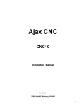
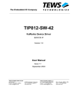
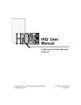
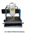
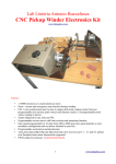
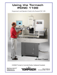
Ajax Mach3 Based CNC Kit
Operator's Manual
Version 1.10 for DC3IOB
(Mach3 is a trademark of Newfangled Solutions, LLC)
Ajax Mach3 Based CNC Kit Operator's Manual
1/65
Disclaimer of Software Warranty
NO WARRANTIES. THE SOFTWARE IS PROVIDED “AS IS” WITHOUT WARRANTY OF ANY
KIND. TO THE MAXIMUM EXTENT PERMITTED BY APPLICABLE LAW, AJAXCNC
DISCLAIMS ALL WARRANTIES, EXPRESSED OR IMPLIED, INCLUDING, BUT NOT LIMITED
TO, IMPLIED WARRANTIES OF MERCHANTABILITY AND FITNESS FOR A PARTICULAR
PURPOSE AND ANY WARRANTY AGAINST INFRINGEMENT, WITH REGARD TO THE
SOFTWARE.
NO LIABILITY FOR DAMAGES. THE ENTIRE RISK AS TO THE QUALITY AND
PERFORMANCE OF THE SOFTWARE IS WITH YOU. SHOULD THE SOFTWARE PROVE
DEFECTIVE, YOU ASSUME THE ENTIRE COST OF ALL NECESSARY SERVICING, REPAIR
OR CORRECTION, AND ANY INCIDENTAL OR CONSEQUENTIAL DAMAGES. TO THE
MAXIMUM EXTENT PERMITTED BY APPLICABLE LAW, IN NO EVENT SHALL AJAXCNC
BE LIABLE FOR ANY DAMAGES WHATSOEVER (INCLUDING, WITHOUT LIMITATION,
DAMAGES FOR LOSS OF BUSINESS PROFITS, BUSINESS INTERRUPTION, LOSS OF
BUSINESS INFORMATION, OR ANY OTHER PECUNIARY LOSS) ARISING OUT OF THE USE
OR INABILITY TO USE THE SOFTWARE, EVEN IF AJAXCNC HAS BEEN ADVISED OF THE
POSSIBILITY OF SUCH DAMAGES.
THE CUSTOMER WILL INDEMNIFY, HOLD HARMLESS AND DEFEND AJAXCNC FROM
AND AGAINST ANY CLAIMS OR LAWSUITS, INCLUDING FOR ATTORNEYS’ FEES, THAT
ARISE OR RESULT FROM THE USE OF THIS SOFTWARE.
CUSTOMER ACKNOWLEDGES THAT CUSTOMER HAS READ THIS AGREEMENT,
UNDERSTAND IT AND AGREES TO BE BOUND BY ITS TERMS AND CONDITIONS.
CUSTOMER FURTHER AGREES THAT IT IS THE COMPLETE AND EXCLUSIVE STATEMENT
OF THE AGREEMENT BETWEEN CUSTOMER AND AJAXCNC WHICH SUPERSEDES ANY
PROPOSAL OR PRIOR AGREEMENT, ORAL OR WRITTEN, AND ANY OTHER
COMMUNICATIONS BETWEEN CUSTOMER AND AJAXCNC RELATING TO THE
SOFTWARE.
Ajax Mach3 Based CNC Kit Operator's Manual
2/65
AjaxCNC
P.O. Box 9012
Milesburg, PA 16853
Tel. 814-360-0279
Fax. 413-793-4886
www.ajaxcnc.com
Limited Hardware Warranty
(1)By accepting delivery or by operating this product,
you the Buyer accept all of the terms of this
warranty. If you do not wish to accept the terms of
this agreement, please contact AjaxCNC
immediately to make arrangements for the return
of the product. Restocking and shipping fees
apply.
(2)All software purchases are nonrefundable.
(3)If payment is returned or rescinded the customer is
responsible for returning all merchandise in likenew condition within 30 days at the customer’s
full expense.
(4)At no time shall AjaxCNC be responsible for any
shipping charges, whether to or from AjaxCNC.
(5)This AjaxCNC product is covered under a limited
warranty for the period of (1) year from the date of
delivery. During this warranty period, AjaxCNC
will repair or replace defective AjaxCNC-provided
parts free of charge. The Buyer understands that
the repair may include replacement of the product,
parts, or components with functionally equivalent
reconditioned parts, products, or components.
(6)Warranty repair is subject to inspection by AjaxCNC
to determine factory defect. Only those parts,
products, or components determined by AjaxCNC
to have factory defect will be covered by this
limited warranty. In the event that AjaxCNC
determines the returned parts were not defective as
shipped from AjaxCNC, the Buyer shall pay all
subsequent costs incurred by AjaxCNC due to part
replacement and/or repair.
(7)An AjaxCNC issued RMA number is required in
order for AjaxCNC to accept return shipments of
defective parts, products, or components. The
Buyer is responsible for the shipping charges
to/from AjaxCNC. All repairs will be sent via
UPS Ground. Expedited shipping charges will
only be incurred at the Buyer’s expense.
(8)AjaxCNC’s warranty applies only to AjaxCNC
provided parts, products, or components.
AjaxCNC is in no way responsible for equipment
or machinery manufactured by or sold by others.
(9)This warranty does not cover unauthorized
modifications of hardware or software made by the
Buyer or others. In the event that modifications
are made, all AjaxCNC warranties and support will
be terminated.
Ajax Mach3 Based CNC Kit Operator's Manual
(10)This warranty does not cover damage caused by
abuse, improper maintenance, improper
installation, operator error, neglect, accident, or
acts of God.
(11)AjaxCNC is in no way responsible for damage
incurred to parts, products, or components during
their installation. The Buyer understands that any
work performed by themselves, or third-party
agents, including AjaxCNC referred Independent
Service Technicians, is NOT covered by this
limited warranty.
(12)In no event will AjaxCNC be liable to you, the
Buyer, for any damages caused by your failure to
perform work or other responsibilities. AjaxCNC
is not responsible for any lost profit, lost savings,
lost earnings, or other incidental or consequential
damages, even if AjaxCNC has been advised of
the possibility of such damages. AjaxCNC is not
liable for any claim made by you based on any
third-party claim.
(13)AjaxCNC makes no express or implied warranties
for this product, with regard to the use,
merchantability or fitness for a particular purpose.
(14)Technical Support is limited and at the sole
discretion of AjaxCNC. Email, phone and on-site
service are available for a fee. Complete details
are available on our website at www.ajaxcnc.com/
tech_support.htm.
(15)This agreement is a contract between the customer
(you) and AjaxCNC. You must read, agree with
and accept all of the terms and conditions
contained in this agreement. AjaxCNC reserves
the right to modify this agreement at anytime and
it shall become effective immediately upon
signing. Your signature below indicates you have
read the entire terms and conditions in this
document and agree to be bound by them.
I have read, understand and accept the above terms
and conditions:
Name (print)
Signature
Date
3/65
Table of Contents
1 Introduction.............................................................................................................................................6
2 Hardware Setup.......................................................................................................................................6
2.1 Ajax MPU11....................................................................................................................................6
2.2 DC3IOB...........................................................................................................................................7
2.3 Image of Connections......................................................................................................................8
2.4 Encoder Basics................................................................................................................................9
3 Software Installation.............................................................................................................................11
4 Mach3 Setup.........................................................................................................................................12
4.1 Axis Setup......................................................................................................................................12
4.2 Spindle Setup.................................................................................................................................14
4.3 Axis Reversal.................................................................................................................................14
4.4 General Brain Setup......................................................................................................................15
4.5 Ajax Coolant Brain........................................................................................................................16
4.6 Ajax Lube Brain............................................................................................................................16
4.7 Ajax Enables Brain........................................................................................................................17
4.8 Ajax Cutoff Brains (X, Y and Z)...................................................................................................18
4.9 Ajax Spindle Brain........................................................................................................................19
4.10 Ajax Continuous Jog Brains (X, Y and Z)...................................................................................20
4.11 Ajax Incremental Jogging Brain..................................................................................................21
4.12 Ajax Limit Inputs Brain...............................................................................................................22
4.13 Ajax Limit Handling Brain..........................................................................................................22
4.14 Ajax Plot Gather Brain................................................................................................................23
4.15 Ajax MPG Axis Brain..................................................................................................................23
4.16 Ajax MPG Disable Brain.............................................................................................................24
4.17 Ajax MPG Enable Brain..............................................................................................................25
4.18 Ajax MPG Multiplier Brain.........................................................................................................26
4.19 Ajax Pendant Aux Brain..............................................................................................................27
4.20 Ajax Pendant Coolant Brain........................................................................................................28
4.21 Ajax Pendant Feed Brain.............................................................................................................29
4.22 Ajax Pendant Jog 1 Brain............................................................................................................30
4.23 Ajax Pendant Jog 2 Brain............................................................................................................31
4.24 Ajax Pendant Jog 3 Brain............................................................................................................32
4.25 Ajax Pendant LEDs Brain...........................................................................................................33
4.26 Ajax Pendant Spindle 1 Brain.....................................................................................................34
4.27 Ajax Pendant Spindle 2 Brain.....................................................................................................34
4.28 Ajax Pendant Spindle 3 Brain.....................................................................................................35
4.29 Add On Boards............................................................................................................................35
4.30 Fourth Axis Setup........................................................................................................................36
4.31 MPG Setup (MPU11 Based).......................................................................................................41
5 Diagnostics and Tuning.........................................................................................................................43
5.1 Axis Plot........................................................................................................................................43
5.2 Ajax Configuration Utility.............................................................................................................44
5.3 Preliminary Motor Tuning.............................................................................................................46
5.4 Initial Positioning..........................................................................................................................46
5.5 Tuning Kp......................................................................................................................................47
Ajax Mach3 Based CNC Kit Operator's Manual
4/65
5.6 Tuning Kd......................................................................................................................................48
5.7 Tuning Kv1....................................................................................................................................49
5.8 Adjusting Kg..................................................................................................................................50
5.9 Adjusting Maximum Velocity........................................................................................................50
5.10 Adjusting Acceleration................................................................................................................52
5.11 Drag Plot Macro..........................................................................................................................53
5.12 Backlash Compensation..............................................................................................................56
6 Mach3 Operation...................................................................................................................................57
6.1 Homing..........................................................................................................................................57
6.2 Jogging..........................................................................................................................................57
6.3 Running a Job................................................................................................................................57
6.4 A Note About Feed Hold...............................................................................................................58
6.5 Rounded Corners...........................................................................................................................58
6.6 Probing and Digitization...............................................................................................................59
7 Appendices............................................................................................................................................61
7.1 Input Reference.............................................................................................................................61
7.2 Output Reference...........................................................................................................................62
7.3 Ajax Mpu11 On-board I/O Reference...........................................................................................64
7.4 Debounce Settings.........................................................................................................................64
7.5 Control Pendant Reference............................................................................................................65
Ajax Mach3 Based CNC Kit Operator's Manual
5/65
1 Introduction
The Mach Ajax Plugin is designed as a simple way to run a CNC machine at high speeds and low
headaches. Instead of driving stepper motors over the parallel port, the plugin allows Mach3 to
smoothly command the motion of servo motors over a direct Ethernet connection. G Code programs
consisting of many small moves (digitized shapes for example) can be run at full speed without
problem.
2 Hardware Setup
The kit you purchased should contain two printed circuit boards – an Ajax MPU11 board and a
DC3IOB.
2.1 Ajax MPU11
The Ajax MPU11 board connects to your computer with a standard ethernet cable. Your computer will
need to have at least one network adapter card installed, though two are recommended if you intend to
use your computer for anything other than CNC operation. It looks like this...
Power
Fiber Optics to
DC3IOB or GPIO4D
A B C Encoders
Ethernet to Computer
X Y Z Encoders
Ajax Mach3 Based CNC Kit Operator's Manual
6/65
2.2 DC3IOB
The DC3IOB connects to your Ajax MPU11 board with 4 fiber optic cables (to isolate your computer
from any electrical feedback that could otherwise cause damage). Only fiber ports 1, 3, 4 and “MPU11
5” are used – the other 2 ports should be capped.
Port 1 on the DC3IOB should connect to port 1 on the Ajax MPU11.
Port 3 on the DC3IOB should connect to port 3 on the Ajax MPU11.
Port 4 on the DC3IOB should connect to port 4 Drive on the Ajax MPU11.
The Port labeled “MPU11 5” on the DC3IOB should connect to port 5 Drive on the Ajax MPU11 (not
port 5 Legacy)
Fiber Optics to
Ajax DSP
Ajax Mach3 Based CNC Kit Operator's Manual
7/65
2.3 Image of Connections
Your major connections should look something like the image below (servos, encoders, and I/O wires
are not shown)
Ajax Mach3 Based CNC Kit Operator's Manual
8/65
2.4 Encoder Basics
Encoder Type:
• Ajax MPU11 hardware requires quadrature, differential encoders which operate on 5VDC. This
is the most common type of encoder. Encoders labeled "TTL type" (non differential) are
unsuitable, and fortunately are quite rare.
Encoder Signals:
• The following signals must be present and wired: A, /A, B, /B, Z, /Z, +5VDC and ground.
Note: The Z channel is sometimes labeled as I, C or "marker". The "/" symbol may also be
expressed as "-", "NOT" or "!" or a line over the letter, it means the signal is the complement
(opposite) of the channel specified.
• Signal levels:
The "low" signal level must be less than 0.5 VDC and the "high" signal level must be at least
3.5 VDC.
Encoder Resolution:
• Typical Machine tool applications (milling machines, lathes and routers) require at least 1000
line (4000 counts per rev) encoders. We recommend and sell 2000 line (8000 counts per rev)
encoders. To achieve reasonable accuracy and smooth motion, the encoder/motor/ballscrew
configuration must achieve a minimum resolution of 20,000 encoder counts per inch of travel
(787 counts/mm). For a typical knee mill which uses a 5tpi (turns per inch) ballscrew and has
the motors belted at a 1:1 ratio, a 1000 line encoder just meets the minimum counts per inch.
Which is 20,000 for smooth motion. The 1000 line encoder will work. However, a 2000 line
encoder (8000 counts per rev) would be a better choice. Older 250 and 500 line encoders will
not work to satisfaction.
Some Examples:
• 5 turns per inch ballscrew belted at 2:1 with the servo motor = 10 turns of the servo motor per
inch of axis travel
• 10 turns per inch x 4000 counts per rev (1000 line) = 40,000 counts per inch
• 10 turns per inch x 8000 counts per rev (2000 line) = 80,000 counts per inch.
• 5 turns per inch ballscrew belted at 1:1 with the servo motor = 5 turns of the servo motor per
inch of axis travel
• 5 turns per inch x 8000 counts per rev = 40,000 counts per inch of axis travel.
Ajax Mach3 Based CNC Kit Operator's Manual
9/65
Encoder wiring
• MUST be shielded, twisted pair cabling.
• Encoder wiring at MPU11:
DB9 Body = Cable Shield
Pin Function
1 No Connection
2 GND
3 Z\
4 A\
5 B\
6Z
7A
8B
9 +5 VDC
Pin Side
Solder Side
Encoder Errors:
• The MPU11 has built in encoder error checking. It will try to cause a fault if your encoder
connections become loose, disconnected, or subject to noise.
• If your encoders do not meet the above specifications, you may encounter encoder error faults.
• For this reason, the plugin configuration utility allows you to disable the encoder error
checking. WARNING: This will prevent the MPU11 from detecting any encoder errors. It
will no longer fault if the encoder is disconnected. If the encoder becomes disconnected, it
may cause a motor run-away situation which will only fault after an axis position error or
a full power without motion fault.
Ajax Mach3 Based CNC Kit Operator's Manual
10/65
3 Software Installation
Before beginning this step, you should have
already installed the Mach3 software from
Newfangled Solutions, LLC.
Insert the CD that came with your kit into your
computer's CD Rom drive, and your computer
should automatically start the setup program for
you. Follow the onscreen prompts, and make sure
you install the Ajax software into the same
directory as your Mach3 software (typically
C:\Mach3).
After the software has been installed, the Setup
program will help you configure your computer so
it can communicate with the Ajax MPU11. In
order to do so, you should select the network
adapter you wish to use with the Ajax MPU11
from the list provided. The IP address of the
selected adapter will be changed to 10.168.41.1,
which is the only address that the Ajax MPU11
recognizes.
NOTE: Two network adapters must be installed in
your computer if you intend to use your computer
to connect to the internet and to the Ajax MPU11
at the same time. That is to say, the Ajax MPU11
requires a dedicated network adapter.
Ajax Mach3 Based CNC Kit Operator's Manual
11/65
4 Mach3 Setup
The setup program should create a shortcut on your desktop labeled “Mach Ajax Plugin”. Clicking on
this shortcut will start Mach3 using our default settings, which will help you get running faster. The
steps below should also help – but please see the full Mach3 Operator's manual for detailed
instructions.
The values shown in the following screen shots are the default values that the setup program establishes
when it is run. You will likely need to deviate from these values, depending on the actual machine you
are setting up.
4.1 Axis Setup
By default, three motor axes (X, Y, and Z) are setup.
In order to change the configuration, go to Config → Ports and Pins in Mach3's menu bar. From here,
click the Motor Outputs tab. Each motor that you intend to use must have a green check mark in the
Enabled column (otherwise it will not be recognized). All other settings on this tab are ignored by the
Mach Ajax Plugin.
Ajax Mach3 Based CNC Kit Operator's Manual
12/65
In addition, each axis motor must also have a green check mark in the Enabled column on the Output
Signals tab (Enable1 is for the X axis, Enable2 is for the Y axis, and so on). This will cause an output
signal to be sent (via Brains) which will in turn cause power to flow to the motor. All other settings on
this tab are ignored by the Mach Ajax plugin.
Also, because the Mach Ajax Plugin is a closed loop system, each axis motor should have an encoder
setup on the Encoder/MPG's tab. Again, a green check mark is needed in the Enabled column, but
Counts/Unit must also be set for each axis.
Ajax Mach3 Based CNC Kit Operator's Manual
13/65
4.2 Spindle Setup
To setup the maximum spindle speed for your mill, select Config → Spindle Setup from Mach3's menu
bar. This max speed value is the value at which full power is delivered to the spindle motor. So, if the
maximum is set to 8000, and the commanded spindle speed is 4000 (“M3 S4000”), half power will be
delivered to the spindle motor.
4.3 Axis Reversal
If you find that the axes of your machine move in the opposite direction of what they should, go to the
Config → Homing/Limits menu and set a green check mark in the Reversed column for any axis you
wish to reverse.
Ajax Mach3 Based CNC Kit Operator's Manual
14/65
4.4 General Brain Setup
Mach3 has a built in programmable control system
(Brains) that allows certain outputs to be set when
certain conditions are met. Your kit comes with several
default brains, which can be enabled or disabled from
Mach3's Operator → Brain Control menu.
Of particular interest are the use of OEM Triggers 1
through 6 to control the Jogging brains and the use of
Input 1 through 3 to control the Plot Gather brain. Also
note that ModBus registers are used in brains to
indicate Ajax MPU11 inputs and outputs (in order to
provide a full range of inputs and outputs). The
ModBus protocol isn't actually used.
If you are controlling more or less than the default of 3
axes, you will also want to review the Ajax Enable
brains that you are using. You may also have to add
brains of your own to control jogging on the additional
axes.
Also, the Ajax Spindle brain assumes that Output 1 and Output 2 will be used to control the spindle
direction and enable state. These are located on the Spindle Setup tab of the Config → Ports and Pins
menu within Mach3. Likewise, the Flood and Mist brains assume the use of Output 4 and 3. These
values are already set, and you shouldn't change these values unless you make corresponding changes
to the spindle control brain.
Ajax Mach3 Based CNC Kit Operator's Manual
15/65
4.5 Ajax Coolant Brain
Mach3 will normally turn on Outputs 3 and 4 to indicate that Mist and Flood coolant relays should be
active – this brain passes those signals along to the MPU11 (using ModBus outputs 3 and 4). However,
the control pendant (which is optional add-on hardware) allows the user to manually control coolant.
The state of ModBus output 788 indicates whether automatic or manual coolant mode is selected (1 for
automatic, 0 for manual) – and if manual coolant mode is selected, the coolant values from the pendant
are passed along instead (789 and 790).
4.6 Ajax Lube Brain
The Ajax Lube Brain turns on ModBus Output 2 whenever the machine is moving, which then gets
passed along to the Ajax MPU11. This should cause your Lube relay to trip on your control board.
Ajax Mach3 Based CNC Kit Operator's Manual
16/65
4.7 Ajax Enables Brain
In order for each of your motors to get power, the corresponding ModBus Output (351 to 356) needs to
be set. Mach3 makes the determination of which motors are Enabled, and this brain simply passes that
information along to the Ajax MPU11.
Ajax Mach3 Based CNC Kit Operator's Manual
17/65
4.8 Ajax Cutoff Brains (X, Y and Z)
These three brains cause the motor enables to turn off in Mach3, whenever a limit switch is tripped.
This is a safety feature to help prevent your machine from crashing into its hard stops should it overrun
its limits. These brains also re-enable power to the motor whenever jogging is attempted and the
corresponding limit switch is not tripped (which allows you to jog your machine off of the limit switch
should you hit it).
Ajax Mach3 Based CNC Kit Operator's Manual
18/65
4.9 Ajax Spindle Brain
The Ajax Spindle Brain determines whether or not the Spindle Enable output (ModBus 14) and the
Spindle Direction output (ModBus 13) should be set – which in turn cause two relays on your control
board to respond. The state of ModBus output 769 is used to indicate whether the optional control
pendant is in automatic spindle control mode (a value of 1) or manual spindle mode (a value of 0). In
automatic mode, Mach's Outputs 1 and 2 are used to determine the values for the Spindle Enable and
Spindle Direction outputs. In manual mode, ModBus output 784 is used to determine whether the
spindle is enabled, and ModBus output 803 is used to indicate its direction (0 for clockwise, 1 for
counterclockwise).
Ajax Mach3 Based CNC Kit Operator's Manual
19/65
4.10 Ajax Continuous Jog Brains (X, Y and Z)
These three brains control continuous jogging, by sending signals to the Ajax MPU11. The signals are
arranged in pairs, and tell the Ajax MPU11 to turn each motor one direction or the other. ModBus
Outputs 361 and 362 control the X axis, for example. So basically, the OEM Trigger values are used to
determine if each axis should be jogged in the positive or negative direction, or not at all (1, -1 or 0).
ModBus Input 750, 751, and 752 are also used to determine if each axis is reversed – and if so, the sign
of the formula is reversed. The limit switch values are also used to prevent continuous jogging toward
a tripped limit switch.
Ajax Mach3 Based CNC Kit Operator's Manual
20/65
4.11 Ajax Incremental Jogging Brain
This brain passes the OEM Trigger presses that control jogging to Jog Button presses in Mach3, but
only if Jogging is allowed. It also prevents movement if the MDI line has cursor focus, by checking
the value of ModBus Input 767.
Ajax Mach3 Based CNC Kit Operator's Manual
21/65
4.12 Ajax Limit Inputs Brain
This brain simply passes the limit switch inputs supplied by the Ajax MPU11 into Mach3's limit switch
inputs.
4.13 Ajax Limit Handling Brain
This brain determines what to do when a limit switch is tripped, and by default it will act as if the Stop
button was pressed. The only exception is if ModBus Output 441 (the ignore errors flag) is set, in
which case no action is taken when the limit switch is tripped (used in the M92 homing macro).
Ajax Mach3 Based CNC Kit Operator's Manual
22/65
4.14 Ajax Plot Gather Brain
This brain checks Inputs 1, 2, and 3 (normally F1, F2, and F3) – and sends a corresponding plot request
to the Ajax MPU11. The Diagnostics and Tuning section below provides more information on how to
use this brain.
4.15 Ajax MPG Axis Brain
The 100 step MPG offered by Ajax CNC has an Axis selection knob, and this brain uses the state of
that knob to tell Mach3 which axis is selected.
Ajax Mach3 Based CNC Kit Operator's Manual
23/65
4.16 Ajax MPG Disable Brain
The axis selection knob on the Ajax MPG also has an “Off” setting. This brain tells Mach3 to disable
the MPG (and return to continuous jog mode) if “Off” is selected. It also disables MPG mode if any of
the limit switches are tripped. NOTE: If you are using a non-Ajax MPG (for example an encoder
plugged into the Encoder 6 port on the Ajax MPU11), this brain will continually disable your MPG
unless the brain itself is disabled.
Ajax Mach3 Based CNC Kit Operator's Manual
24/65
4.17 Ajax MPG Enable Brain
This brain causes the axis selection knob of the Ajax MPG to automatically turn MPG mode on,
whenever the knob is not turned to the “Off” position. It also causes the LED on the MPG to light up
(ModBus output 481) if Mach3 is in MPG mode.
Ajax Mach3 Based CNC Kit Operator's Manual
25/65
4.18 Ajax MPG Multiplier Brain
This brain causes the multiplier knob (x1, x10, x100) on the Ajax MPG to select the jog increment to
use. These are setup by default to 0.001, 0.01, and 0.1 respectively. These values can be configured in
Mach3's Config → General Config menu.
Ajax Mach3 Based CNC Kit Operator's Manual
26/65
4.19 Ajax Pendant Aux Brain
Ajax CNC offers an operator's control pendant, and this brain simply shows how to use the Aux inputs
to light up the LEDs of the associated keys.
Ajax Mach3 Based CNC Kit Operator's Manual
27/65
4.20 Ajax Pendant Coolant Brain
This brain allows the user of a control pendant to manually control the Flood and Mist relays.
Ajax Mach3 Based CNC Kit Operator's Manual
28/65
4.21 Ajax Pendant Feed Brain
This brain converts the (8 or 12) output bits generated by the Feedrate Override knob on the Ajax
control pendant into a number that Mach3 can use for its feedrate.
Ajax Mach3 Based CNC Kit Operator's Manual
29/65
4.22 Ajax Pendant Jog 1 Brain
This brain makes the Incremental / Continuous jog mode selection button on the Ajax control pendant
function.
Ajax Mach3 Based CNC Kit Operator's Manual
30/65
4.23 Ajax Pendant Jog 2 Brain
This brain makes most of the other jog-related keys on the Ajax control pendant function, simply
passing the input values through to Mach3 as the corresponding button presses. NOTE: This brain
overrides the OEM Trigger values. If you are using a control pendant, you should change your settings
in the Config → Ports and Pins → Input Signals menu such that the OEM Trigger values are not
emulated by the keyboard.
Ajax Mach3 Based CNC Kit Operator's Manual
31/65
4.24 Ajax Pendant Jog 3 Brain
This brain controls the Fast/Slow button on the Ajax control pendant (the turtle / rabbit button). It also
sends the state of that button to ModBus output 377, so the Ajax MPU11 knows whether it should
perform a fast or slow jog.
Ajax Mach3 Based CNC Kit Operator's Manual
32/65
4.25 Ajax Pendant LEDs Brain
This brain determines which of the Ajax control pendant LEDs should be lit, and which should be dark.
Some LEDs are controlled by other brains, but this is where most of the simple ones are located.
Ajax Mach3 Based CNC Kit Operator's Manual
33/65
4.26 Ajax Pendant Spindle 1 Brain
This brain controls the state of the Automatic/Manual spindle setting on the Ajax control pendant.
4.27 Ajax Pendant Spindle 2 Brain
This brain causes the Clockwise/Counter-Clockwise spindle setting on the Ajax control pendant to
function. The setting itself is stored in ModBus output 803 – with a 0 indicating clockwise and a 1
indicating counter clockwise.
Ajax Mach3 Based CNC Kit Operator's Manual
34/65
4.28 Ajax Pendant Spindle 3 Brain
This brain allows the Spindle +, 100%, -, Stop and Start keys on the Ajax control pendant to function.
4.29 Add On Boards
If you have purchased a PLCADD1616 or other expansion board, the ajaxlog.txt file can assist you in
determining the correct IO range to use for your particular board.
Ajax Mach3 Based CNC Kit Operator's Manual
35/65
4.30 Fourth Axis Setup
If you would like to setup a fourth axis with your Ajax system, you will need to alter your settings in
several different places...
First, go to the Config → Ports and Pins menu. Select the Motor Outputs tab and mark the fourth axis
(A Axis) as enabled. This will allow Mach3 to recognize your fourth axis.
Next, go to the Output Signals tab, and mark Enable4 as Enabled. This allows your fourth axis to get
power.
Ajax Mach3 Based CNC Kit Operator's Manual
36/65
Then, click on the Encoder/MPG's tab and set Encoder4 as Enabled – and also fill in the appropriate
value for Counts/Unit. This allows your fourth axis to measure angles (or distances) accurately.
Following that, go to the Input Signals tab. Setup OEM Trigger 7 and 8 to be emulated with the
keypresses you'd like to use for jogging the fourth axis.
Ajax Mach3 Based CNC Kit Operator's Manual
37/65
Next click on the Operator → Brain Control menu and mark the Ajax Fourth Axis.brn brain as being
Enabled. This brain converts the OEM trigger signals into actual jog commands on the fourth axis.
At this point, your fourth axis should be somewhat functional – however,
the fourth axis motor may be controlled by the X axis, rather than the A
axis as expected (for a DC3IOB kit and a DC1 add on board – GP4IOD
users can probably ignore this step). This is because the
DC3IOB/MPU11 hardware detects drives in reverse order. While it's
possible to setup your machine so it works like this, it will make more
sense if we remap each of the axes to control the motor we expect it to
control.
To do this, use the Config → Config Plugins → AjaxPlugin menu, and
modify the DriveNumber and EncoderNumber settings for each axis.
The PlugIn Control → Mach Ajax Plugin menu can help you determine
the correct drives to use, though it will typically be 2, 3, 4, 1 (as shown
below).
Ajax Mach3 Based CNC Kit Operator's Manual
38/65
NOTE: You may also need to modify the M92 macro if you use an input other than 30 for rotary
axis home.
Ajax Mach3 Based CNC Kit Operator's Manual
39/65
Drive Number Chart
Drive Number
Location
Description
1
Drive Bus Channel 1
2
Drive Bus Channel 2
3
Drive Bus Channel 3
4
Drive Bus Channel 4
5
Drive Bus Channel 5
6
Drive Bus Channel 6
7
Drive Bus Channel 7
Drive types are DC3IOB, DC1, ACSingle, and OPTIC4.
Other drive types may be added in the future. The drive
which is on drive channel one will normally display a 1 on the
LED display. Drive channel 1 gets assigned by the FPGA to
the last drive on the Drive bus chain and sequential numbers
are added back to the device with the fiber optic cable
connected to the MPU11. A DC3IOB will take 3 drive
channels, one for each axis output, and an OPTIC4 will take
4 drive channels.
8
Drive Bus Channel 8
9
GPIO4D Drive Out 1
10
GPIO4D Drive Out 2
11
GPIO4D Drive Out 3
12
GPIO4D Drive Out 4
13
Legacy DC 1
14
Legacy DC 2
15
Legacy DC 3
16
Legacy DC 4
Implemented through outputs on the plc bus which are written
to at 4000hz. It is possible to have a GPIO4D connected to
the PLC bus and a drive to connected to the drive bus at the
same time.
Legacy DC drives (DC3IO) are not compatible with the above
drive bus drives.
Future: Drive numbers could be expanded to support other drive types such as SD1
Encoder Index Chart
Encoder Index Location
Description
1
MPU11 onboard Encoder 1
2
MPU11 onboard Encoder 2
3
MPU11 onboard Encoder 3
4
MPU11 onboard Encoder 4
5
MPU11 onboard Encoder 5
6
MPU11 onboard Encoder 6
7
Drive Bus Channel 1 Encoder
8
Drive Bus Channel 2 Encoder
9
Drive Bus Channel 3 Encoder
10
Drive Bus Channel 4 Encoder
11
Drive Bus Channel 5 Encoder
12
Drive Bus Channel 6 Encoder
13
Drive Bus Channel 7 Encoder
14
Drive Bus Channel 8 Encoder
15
MPU11 onboard MPG Encoder Input MPG connector, which has no index pulse signal
Ajax Mach3 Based CNC Kit Operator's Manual
The encoder inputs that are on the MPU11. Labeled
Encoder 1- Encoder 6
An encoder connected to a drive bus device. An
Optic4 has 1 encoder per channel.
40/65
4.31 MPG Setup (MPU11 Based)
The Ajax MPU11 and Plugin have built in support for an MPG
with a 5 volt differential encoder. The Ajax Plugin comes with
several brains which work with a single Ajax supplied MPG (as
shown on right). If you have a different MPG, the brains will
work as long as you follow the MPG wiring diagram in
MPU11_AND_CABLES.pdf. The brains control the axis
selection, multiplier, and MPG enable/disable. They also
control the LED indicator light on the MPG. It is not necessary
to have the supplied brains working, as long as you can specify
the axis selection and multiplier in Mach.
•
Detents: The marks on the MPG handwheel. They
provide tactile feedback and cause the encoder to stop
exactly on a detent. The MPG to the right has 100
detents per revolution.
•
Windup Mode: The MPU11 MPG has two modes of operation. If Windup Mode is on the
MPG will move the exact number of steps that the user commanded. If Windup Mode is off,
the MPG will stop short if the user cranks the MPG faster than the motor can handle. The Ajax
Plugin automatically turns off Windup Mode for jog-steps greater than .01 inches or greater
than .2 mm in metric mode. Windup mode is turned on for smaller jog-increments.
•
MPG Feedrate: It is recommended that you set this value to the the highest maximum
velocities for all of your axes. The MPG will try to move the motors as fast as the user cranks
the hand wheel. However, it is limited by the MPG Feedrate, shown to the right, and the
maximum velocity of the selected axis. It is also effected by the acceleration rate for the
selected axis. If your MPG is moving slower than you expect, check your MPG Feedrate which
is in Mach's MPG Mode window. (Press Tab from the main screen)
•
Counts/Detent: The MPG needs to know how many encoder counts per detent there are. The
MPG provided by Ajax has 4 encoder counts per detent. In order to change this value, go to
Config → Ports and Pins in Mach3's menu bar. From here, click the Encoder/MPG's tab. The
Counts per Detent are set in the Counts per Units column. If your MPG doesn't have detents,
that's ok. The MPU11 needs to know how many encoder counts cause 1 jog-increment of
movement (in x1 mode).
Enabled: The enabled column must be checked in the Encoder/MPG's tab for the MPG to
work.
•
Ajax Mach3 Based CNC Kit Operator's Manual
41/65
MPG Enable and Counts/Detent Configuration
NOTE: The Velocity column in this window has NO effect for the MPG row. (When using an MPU11
based MPG)
•
Multiple MPGs: The MPU11 supports up to 3 MPG's which can be connected to any available
encoder input.
•
MPG Encoder Inputs: The MPG encoder indexes tell the MPU11 which encoder to read as an
mpg. The MPG header is the default encoder input for the first MPG. This can be changed in
the mach_ajax.xml configuration file. You can also specify encoder inputs for the other two
mpgs. See the Encoder Index chart above in section 4.30.
Ajax Mach3 Based CNC Kit Operator's Manual
42/65
5 Diagnostics and Tuning
The Mach Ajax Plugin has several features to assist you in diagnosing and resolving problems you may
encounter with your machine.
5.1 Axis Plot
To perform an axis plot, the Ajax Plot Gather brain must be enabled. This brain will ask the Ajax
MPU11 to record its position, velocity, acceleration and error values for a 2 second period of time, for a
given axis. These values are then sent to your computer where they are displayed in an graphical form.
Input 1 (X axis), Input 2 (Y axis) and Input 3 (Z axis) are used to select which axis to plot, and are by
default bound to the F1, F2, and F3 keys. Each plot will also be saved to your computer's hard drive
for later reference (C:\Mach3\Ajax directory by default).
mSecs
AbsError
SumAbsError
AbsVel
ExpVel
AbsPos
ExpPos
The time at which the sample was taken in milliseconds
The absolute error, which is the difference (in encoder counts) between where the
machine should be and where it actually is.
The sum of absolute error, which is a running total of the absolute error value.
This number is often quite large, so a Y Scaling factor of 0.01 can be useful.
The absolute velocity, as measured in encoder counts per millisecond. This value
tells you how fast your motor is actually spinning at any given time.
The expected velocity, as measured in encoder counts per millisecond. This
value tells you how fast your motor is trying to spin.
The absolute position, as measured in encoder counts. This value tells you where
the machine is at any given time.
The expected position, as measured in encoder counts. This value tells you
where the machine is supposed to be at any given time.
Ajax Mach3 Based CNC Kit Operator's Manual
43/65
5.2 Ajax Configuration Utility
The Mach Ajax Plugin comes with its own configuration utility that allows the setup of several
additional parameters specific to your servo motors – or specific to the Ajax MPU11. To access this
utility, select Config → Config Plugins from Mach3's menu bar, then click the yellow Config square.
NOTE: You may need to install Microsoft's .NET framework for this configuration menu to function.
Kp, iL, Kg, Ki, Kv1, Kd, and Ka are used to calculate the amount of power each motor should
receive, in order for the machine to follow its intended path as best as possible. The default values will
probably be pretty close to what you want for your motors, but the steps below will help you tweak the
numbers to reduce errors and oscillations. In general, you should not alter Ki, Ka, iL or Kg.
CountsPerRev is the number of encoder counts in a single rotation of the motor
Drive Number is used to determine which motor should get power when an axis is commanded to
move. In most cases, these should be set to 0 – which will cause the MPU11 to autodetect.
Encoder Number is used to determine which encoder should be used to determine the actual position
of each axis. Again, these should probably be set to 0 for autodetection.
Ajax Mach3 Based CNC Kit Operator's Manual
44/65
Backlash is used to counteract mechanical play in your machine (where the motor moves slightly
before the table itself)
Backlash Accel Multiplier is used to determine how quickly backlash is taken up, and the default
value of 0.1 should work well in most cases. Unless you have access to a sophisticated testing system,
you probably shouldn't change this.
Fast Jog Rate and Slow Jog Rate are used for continuous jogging. Which is in use, depends on the
state of ModBus output 377.
Max Following Error is used to trigger a critical error if the Ajax MPU11 is missing its intended
position by too great a distance, for too long a time period. The length of that time period is equal to
the amount of time it takes for a motor to accelerate from a stop to full speed.
Move To Index Pulse Speed is 4. Leave it that way. It controls how quickly the MPU11 performs the
most critical portion of the homing sequence, and modifying it could cause the MPU11 to home
inconsistently.
Command Buffer is the number of milliseconds that the MPU11 will hold movement commands
before executing them. If this number is too low, the MPU11 is more prone to communication errors
and vector starvation. As the number gets higher and higher, there will be a longer and longer delay
before the MPU11 responds.
Communication Time Out determines how long the Ajax plugin can go without hearing from the
MPU11, before entering an EStop state.
Spindle Low Bit and Spindle High Bit are used to tell the plugin where it should write the spindle
speed value. These are usually set to 0 to allow the MPU11 to autodetect.
High Power Percent and High Power Time are used to cause an EStop if any single motor is being
driven too hard for too long, in order to prevent damage to the motors due to overheating. The default
values should work well.
Probe Input and Probe Input State are used when doing a G31 probing movement to determine when
the probe has tripped.
Stop on Encoder Error and Message on Encoder Error should both be set to 1. However, some
encoders may constantly trigger an encoder error if the are under-voltage, despite working well
otherwise. In that case, these values can be used to suppress the encoder error – however doing so
could cause a dangerous situation if an encoder ever becomes disconnected.
Onboard MPG 1, 2 and 3 are used to specify which encoders control the MPU11's hardware MPGs
(handwheels).
Ajax Mach3 Based CNC Kit Operator's Manual
45/65
5.3 Preliminary Motor Tuning
Go to Mach3's Config → Motor Tuning menu, and set the “Steps Per” value (usually the same as the
Counts/Unit setting from the Encoder/MPG tab) for each axis. Then click Save Axis Settings and
repeat for each axis that you intend to use.
At this point, leave Velocity at the default of 120 inches per minute and Acceleration at 10 inches per
second per second. The “Step Pulse” and “Dir Pulse” are not used by the Mach Ajax plugin at all.
5.4 Initial Positioning
Position your machine such that the tool has ample
clearance on all sides (centered on the table and z
raised midway). Zero the position at this point.
This will help prevent damage to your machine in
the following instructions, and you should return to
this position after each tuning movement. Also be
sure to keep a hand on EStop, as heavy oscillations
could cause damage.
Another note – when doing these tuning movements
on the Z axis, do the movement away from the table and return to your initial position with a slow
movement. That will help prevent running the tool into the table.
Ajax Mach3 Based CNC Kit Operator's Manual
46/65
5.5 Tuning Kp
Kp is the first value you should adjust, and it should range from 0.2 to 2.34. From your initial location,
perform a 1 inch movement at 120 inches per minute (ie “G1 X1.0 F120”), and generate a plot after the
movement has finished (Press F1).
When looking at the plot, hide all lines except AbsError, AbsVel and ExpVel – then click AutoZoom to
fit the plot to the screen.
If Kp is too high, the motor will run ahead of where it should be from the start of the move. If your
plot looks like this sample below (where AbsError dips at the start of a move), your Kp should be
reduced by 0.05 and the test should be run again from the initial position (also press the Reset button in
Mach3 a few times to make sure the new value is taken).
If Kp is too low, the motor will trail behind of where it should be. If your plot looks like the plot below
(with AbsError rising at the start of the move), your Kp should be increased by 0.05 and the test
repeated (from the initial location).
Ajax Mach3 Based CNC Kit Operator's Manual
47/65
5.6 Tuning Kd
Kd is the next value you should adjust, and it should range from 0.2 to 1.5. Return to your center point
and perform a 1 inch movement at 120 inches per minute, and generate a plot.
Again, hide all lines except AbsError, AbsVel and ExpVel.
If Kd is too low, you will get low frequency oscillations, primarily at the end of the move. If your plot
looks similar to the one below, try increasing Kd by 0.05 and running the test again.
If Kd is too high, you will get a high frequency oscillation resulting in instability and motor whining.
If your motor whines loudly, hit EStop immediately and reduce Kd by 0.05. Do not perform a
movement if your motor is whining – as the small initial error that causes the whining will quickly
build into a larger and larger error, causing a larger and larger oscillation (your machine will shake
violently).
Ajax Mach3 Based CNC Kit Operator's Manual
48/65
5.7 Tuning Kv1
Kv1 is used for making long term adjustments, and its effects are most noticeable on the sum of
absolute error. Common values for Kv1 are 7.8 to 15.6 on the X axis, 9.4 – 17.2 on the Y axis (higher
because it carries the weight of the X) and 2.3 – 7.8 on the Z axis.
Return to your center point and perform a 1 inch movement at 120 inches per minute, and generate a
plot. This time, hide all lines except SumAbsError, AbsVel and ExpVel. You may also want to scale
SumAbsError by 0.01 so it fits on your screen better.
If Kv1 is too low, the plot will look something like this. Try increasing Kv1 by 3 and running the test
again.
If Kv1 is too high, the plot will look something like this. Try decreasing Kv1 by 3 and running the test
again.
Ajax Mach3 Based CNC Kit Operator's Manual
49/65
5.8 Adjusting Kg
In general, you should not have to adjust Kg. It is the Gravity constant, and is used to counteract an
unbalanced axis. Typical ranges for Kg are -4 to 4 on the X and Y axes and -8 to 8 on the Z axis.
Situations where a Kg value may be needed are as follow...
•A bed mill with an incorrect weight on the counter balance.
•A loose gib.
•A failing support bearing.
5.9 Adjusting Maximum Velocity
At this point, your motor should be moving with very little error – and now it is time to determine the
maximum velocity of the motor. Return to Mach3's Config → Motor Tuning menu, and increase the
velocity by 50 inches per minute (this velocity setting determines the maximum feedrate your motor
will attain). Remember to Save the Axis settings as well.
Return to your initial position and run an 4 inch move (make sure you have clearance) at the new
feedrate (ie “G1 X4.0 F170”). Plot the result and ensure that the actual velocity and expected velocities
are very closely matched (like the image below).
Ajax Mach3 Based CNC Kit Operator's Manual
50/65
If your plot is triangle shaped (with no flat area on the top), your motor did not attain the maximum
velocity you set – but only because the distance you moved was too short. Increase the length of your
movement and try the movement again (make sure there's ample clearance so the machine doesn't crash
into itself).
Repeat this process until the actual velocity fails to keep up with the expected velocity (like one of the
images below). This may also cause a position error. Reduce your velocity to the last known good
value.
The following formula may also help – but stay 10-20% below the actual maximum attained.
VelocityInchesPerMinute = AbsVel * 1000 * 60 / EncoderCountsPerInch
Ajax Mach3 Based CNC Kit Operator's Manual
51/65
5.10 Adjusting Acceleration
Now that the motor is reaching its maximum velocity,
we can adjust the rate of acceleration. Return to
Mach3's Config → Motor Tuning menu, and increase
the acceleration by 2 inches per second per second,
then click the Save Axis Settings button.
Now, return to your initial position and run another test
movement (again make sure you have adequate
clearance). The length of the movement should be
sufficient for the motor to reach its maximum velocity
(as in the previous step) – and should look something
like the plot below
As you gradually increase the acceleration rate, the plot will look more and more like the following
image. Notice the Absolute Error values at the start and end of the movement – this tells you how
many encoder counts the tool is off its desired position. If this value becomes too great, you may wish
to back the acceleration down a bit. (In the image, we are off by 57 counts maximum – at 40,000
counts per inch, which translates into 0.001425 inches which may or may not be acceptable)
Ajax Mach3 Based CNC Kit Operator's Manual
52/65
You will definitely want to reduce the acceleration rate if the absolute velocity fails to keep pace with
the expected velocity, or if it overshoots. The following image shows both of these conditions (you
may need to zoom in to see this – shift and the right mouse button will allow a non-proportional zoom,
which may also be helpful).
5.11 Drag Plot Macro
Typing M4321 on Mach3's MDI line will cause the
Drag Plot Macro to run. This macro can help you
visualize the amount of friction your machine
experiences as it moves between the soft travel limits
for any axis.
Before running this macro, setup your Soft Travel
limits for each axis (in Config → Homing / Limits).
In general, if the green lines are outside of the red
box (and all other settings are correct for the motor),
the drag is excessive for that axis. It can also help
you determine where along its track your machine is
binding. The image below shows a typical drag plot,
with acceptable levels of drag throughout the course
of the machine's movement on the X axis.
Ajax Mach3 Based CNC Kit Operator's Manual
53/65
The next image shows a plot with heavy resistance (two men pushing against the table at three different
points), as the machine made its movement. If the cause was unknown, a plot like this would indicate
major trouble spots at two spots along the axis of travel (-3 and -2), and a minor trouble spot (at 2.5).
The image below shows a drag plot for an unbalanced Z axis.
The next image shows an example drag plot with all around too much drag, which could be due to
inadequate lubrication, chips and debris, rust, or tight gibs.
Ajax Mach3 Based CNC Kit Operator's Manual
54/65
The next example shows a drag plot of an axis that has a misaligned ball screw. The axis is tight near
the ends of travel since the ballscrew is not concentric with the support bearings.
The next example shows a drag plot of a stick-slip type of action, which could be the result of
inadequate lubrication, rust, dirt/debris on the way, or an incorrectly installed gib. If the axis is
controlled with a pulley system, it could also be off center.
Ajax Mach3 Based CNC Kit Operator's Manual
55/65
5.12 Backlash Compensation
When a motor is turning one direction – then reverses and goes the other direction, your machine may
hesitate slightly before moving in that opposite direction. This is a normal occurrence caused by
looseness or wear, and is called backlash.
If you measure the amount of backlash, the Ajax MPU11 can be instructed to compensate for it. Use
the Ajax Configuration Utility to enter the values you measured (Config → Config Plugins → yellow
Config square). Enter the amount of backlash on the Backlash row. The BacklashAccelMultiplier row
is used to determine how quickly the backlash should be taken up – a value of 0.1 is usually sufficient
(meaning that backlash will be taken up at one tenth the maximum acceleration rate of that axis).
NOTE: It is required that the machine is rehomed after changing Backlash Compensation.
Ajax Mach3 Based CNC Kit Operator's Manual
56/65
6 Mach3 Operation
This section is intended as a brief overview of how to operate Mach3 with the Mach Ajax Plugin.
Please refer to the full Mach3 user's manual for more detailed instructions.
6.1 Homing
Homing can be performed by typing “M92 P#” on Mach3's MDI line. This will cause the axis
specified by the # sign (1 for X, 2 for Y, 3 for Z) to do a positive homing movement until it hits the
limit switch, then it will back off until it reaches the index pulse of the encoder.
Multiple axes can be homed simultaneously by specifying Q and R values as well. For example, “M92
P1 Q2 R3” will cause the X, Y and Z axes to home in the positive direction. Homing can be performed
in the negative direction by adding 10 to the numbers – for example “M92 P11 Q12 R13”. The
M92.m1s file in the Macros directory is the script that handles this behavior.
6.2 Jogging
By default jogging can be performed using the Left and Right cursor keys for X movement, the Up and
Down cursor keys for Y movement, and the Page Up and Page Down keys for Z movement. These can
be reconfigured by changing OEM Trigger 1 through 6 in the Input Signals tab of the Config → Ports
and Pins menu, or by creating a custom brain to set the appropriate values.
Continuous jogging is performed at the slow jog rate specified in the Ajax Configuration Utility.
6.3 Running a Job
The
button will allow you to load a text file that contains G-Code movements to
control your machine. Before running the job, read through the code so you know what size and type
of tool to use and where to set your part zeroes. Check the ToolPath screen in Mach3 to verify that
your Program Limits are acceptable (upper right hand corner). Also be wary of any G54, G55, G56,
G57, G58 and G59 codes that may be present (an unexpected coordinate system change can ruin your
day).
When starting out, set the Feed Rate Override to a
low percentage, so you have time to react if
something unexpected does happen. Cutting in the
air is also a good idea.
When you're all ready, the Cycle Start button will
start the job running.
Ajax Mach3 Based CNC Kit Operator's Manual
57/65
6.4 A Note About Feed Hold
As of this time, Feed Hold does not work perfectly with the Mach Ajax Plugin. Specifically, jogging
and MDI commands should not be used when Feed Hold is active as unintentional or delayed motion
may occur.
6.5 Rounded Corners
Mach3 can either operate in Constant Velocity mode (CV mode) or Exact Stop mode. CV mode is
enabled by default, and has the advantage of stringing movements together into one long continuous
motion – keeping the specified feedrate as best as possible. Exact Stop mode causes the machine to
stop motion after each G Code command is issued.
CV mode has a tendency to cause your machine to round tight corners (an effect which is more
pronounced at higher feedrates). The images below show a box shaped movement on the left, and the
actual path taken by the machine on the right.
In order to combat that tendency of CV mode and to
give you greater control over your machine's behavior,
Mach3's Config → General Config menu can be used to
set several additional parameters (in the CV Control
section). “Stop CV on angles >” is set to 70 by default,
and will cause an exact stop in the case shown above (so
the final cut comes out as a square) – a hexagon (with 60
degree angles) would still exhibit this rounding behavior, unless the setting was further reduced.
Another option that works well is the CV Dist Tolerance option, which limits the maximum amount of
rounding that occurs to the value specified.
Ajax Mach3 Based CNC Kit Operator's Manual
58/65
6.6 Probing and Digitization
The Ajax MPU11 supports high speed probing through the use of the G31 command – however the
current implementation differs slightly from the normal Mach3 implementation. In particular, the point
of contact is written to OEM DROs 2000 through 2007, and OEM DRO 1999 is used to indicate
whether or not a contact has occurred. Also, when using G31 within a macro to digitize an object, all
output should be explicitly written to a file (rather than relying on the OpenDigFile and CloseDigFile
functions) – the macro should also wait until the G31 is complete before issuing any further commands.
The G31 operates much like a G1, and moves at the current feedrate to the specified position. What
feedrate to use will depend on the probe you are using, but in general, slower probing will give more
accurate results. If the feedrate is too high, it is possible to damage the probe or part – since the
machine will need time to decelerate after registering a probe hit.
The M9999 macro (which is provided with your kit) shows a simple example of how to perform a grid
digitization with the Ajax hardware. This example could be improved upon in several ways – however
it shows the basic techniques which should be employed.
WARNING
Do not turn on the spindle when a probe is inserted – doing so can cause
the probe to fly out and embed itself in a nearby wall/person.
Ajax Mach3 Based CNC Kit Operator's Manual
59/65
In order to use the G31 probing command, you will first need to attach your probe to one of the
hardware inputs. The Ajax MPU11 has a high speed probe input channel (input 481) that allows the
probe to be sampled at 4000 times per second (which yields greater accuracy), however any normal
input on your DC3IOB / GPIO4D can be used.
Next, use the Ajax Configuration Utility (Config → Config Plugins → yellow Config square) to tell the
Ajax Plugin which input the Probe is using, and whether the probe is normally open or normally
closed.
Make sure you test the G31 command in air to ensure that your probe works correctly and consistently.
Ajax Mach3 Based CNC Kit Operator's Manual
60/65
7 Appendices
7.1 Input Reference
The values in this section can be read by Brains by using ModBus inputs.
Stall: Position Error
Input 351
Stall: Full Power without Motion
Input 352
Stall: Encoder Error or Encoder Warning
Input 353
Stall: Communication Error
Input 354
Jogging: Travel Limit reached
Does not require a Clear Stop Reason. Will clear
whenever the Jogging output goes low.
Input 355
Stall: Following Error
Input 356
Stall: Vector Starvation
Input 357
Drive Fault
Input 358
PLC Fault
Input 359
Axis Error Bit 0
Input 361
Axis Error Bit 1
Input 362
Axis Error Bit 2
Input 363
PLC Type bit 0
Input 364
PLC Type bit 1
Input 365
PLC Type bit 2
Input 366
Operation Complete
Input 367
Homing:
(reset when index pulse move starts
set when index pulse move is finished)
Mpg still moving Error
Input 368
Probed Tripped
Input 369 (set when the mpu11 detects a probe trip, Reset
on the Rising edge of the Enable Probe Detection bit)
Local Inputs (Mpu11 Onboard Inputs)
481-512
Axis 0 Reversed
Input 750 (set to 1 if the axis is reversed, so the continuous
jogging brains can determine which direction to move)
Axis 1 Reversed
Input 751
Axis 2 Reversed
Input 752
Axis 3 Reversed
Input 753
Axis 4 Reversed
Input 754
Drive Type bits: DC3IOB = 0, GP4IOD = 1
Ajax Mach3 Based CNC Kit Operator's Manual
61/65
7.2 Output Reference
Most of the values in this section can be written to by Brains by using ModBus outputs. Some (such as
Output 380) are controlled directly by the Mach Ajax Plugin.
Axis Enable 1
Output 351
Axis Enable 2
Output 352
Axis Enable 3
Output 353
Axis Enable 4
Output 354
Axis Enable 5
Output 355
Axis Enable 6
Output 356
Axis Enable 7
Output 357
Axis Enable 8
Output 358
Master Enable
Output 351 or Output 352 or Output 353 or Output 354 or
Output 355 or Output 356 or
Output 357 or Output 358
Start Plot Dump (Ethernet debug packets)
Output 359
Clear Stop Reason
Output 360
Axis 1 Jog Positive
Output 361
Axis 1 Jog Negative
Output 362
Axis 2 Jog Positive
Output 363
Axis 2 Jog Negative
Output 364
Axis 3 Jog Positive
Output 365
Axis 3 Jog Negative
Output 366
Axis 4 Jog Positive
Output 367
Axis 4 Jog Negative
Output 368
Axis 5 Jog Positive
Output 369
Axis 5 Jog Negative
Output 370
Axis 6 Jog Positive
Output 371
Axis 6 Jog Negative
Output 372
Axis 7 Jog Positive
Output 373
Axis 7 Jog Negative
Output 374
Axis 8 Jog Positive
Output 375
Axis 8 Jog Negative
Output 376
Fast Jog
Output 377
Decel Bit
Output 378 cause mpu11 to decel and purge buffers until
Clear Stall Error is set.
Enable Jogging
Output 380
Move Axis 1 to index pulse positive
Output 381
Ajax Mach3 Based CNC Kit Operator's Manual
low = slow jog, high = fast jog
62/65
Move Axis 1 to index pulse negative
Output 382
Move Axis 2 to index pulse positive
Output 383
Move Axis 2 to index pulse negative
Output 384
Move Axis 3 to index pulse positive
Output 385
Move Axis 3 to index pulse negative
Output 386
Move Axis 4 to index pulse positive
Output 387
Move Axis 4 to index pulse negative
Output 388
Move Axis 5 to index pulse positive
Output 389
Move Axis 5 to index pulse negative
Output 390
Move Axis 6 to index pulse positive
Output 391
Move Axis 6 to index pulse negative
Output 392
Move Axis 7 to index pulse positive
Output 393
Move Axis 7 to index pulse negative
Output 394
Move Axis 8 to index pulse positive
Output 395
Move Axis 8 to index pulse negative
Output 396
Set Axis 1 Home
Output 397
Set Axis 2 Home
Output 398
Set Axis 3 Home
Output 399
Set Axis 4 Home
Output 400
Set Axis 5 Home
Output 401
Set Axis 6 Home
Output 402
Set Axis 7 Home
Output 403
Set Axis 8 Home
Output 404
Gather/Drag Axis Bit 0
Output 405
These 3 bits define the axis number (0-7)
Gather/Drag Axis Bit 1
Output 406
for the gather.
Gather/Drag Axis Bit 2
Output 407
Bit 0 is the least significant bit
Start Gather Dump
Output 408 (starts a Binary dump of data)
Allow jogging even if MDI window has focus (special for
homing and other macros)
Output 440
Ignore Following and Full Power w/o Motion Errors. This
also causes the Ajax Limit Handling brain to ignore limit
switches.
Output 441
Enable Probe Detection / Position Event Capture
Output 442 (Plugin Resets after receiving captured
positions)
Local Outputs (Mpu11 Onboard Outputs)
481-512
Jog Panel Outputs
768-1023
Ajax Mach3 Based CNC Kit Operator's Manual
63/65
7.3 Ajax Mpu11 On-board I/O Reference
The Ajax Mpu11 board has built in inputs and outputs which are mapped to the following ModBus I/O.
The first four inputs are probing inputs which are connected via the probe connector. The MPG I/O are
connected via the mpg encoder connector. Any I/0 not shown in this chart is unimplemented.
Input Specification
ModBus
Input
Number
481
482
483
484
485
486
487
488
489
490
491
492
493
494
495
496
497
498
Input Location
Function
Type
Connector
Pin
Mechanical Probe
DSP Probe
Probe Detect
Probe Auxiliary
MPG x1
MPG x10
MPG x100
MPG Axis 1
MPG Axis 2
MPG Axis 3
MPG Axis 4
MPG Axis 5
MPG Axis 6
MPG Axis 7
MPG Axis 8
MPG Aux 1
MPG Aux 2
MPG Aux 3
12VDC Opto
12VDC Opto
12VDC Opto
12VDC Opto
5VDC
5VDC
5VDC
5VDC
5VDC
5VDC
5VDC
5VDC
5VDC
5VDC
5VDC
5VDC
5VDC
5VDC
H3
H3
H3
H3
H4
H4
H4
H4
H4
H4
H4
H4
H4
H4
H4
H4
H4
H4
6
4
8
10
9
11
13
4
6
8
10
12
14
16
18
15
20
22
Output Specification
ModBus
Output
Number
481
482
483
Output Location
Function
Type
Connector
Pin
MPG LED
MPG Aux 1
MPG Aux 2
Open Collector
Open Collector
Open Collector
H4
H4
H4
17
19
21
*Open Collector outputs are pulled up to 5V
*5 VDC inputs are not isolated
7.4 Debounce Settings
Starting in version 1.10, All inputs, on all PLC bus devices and add on boards, the jog pendent,
and the on-board Ajax Mpu11 inputs have a 1.5 millisecond debounce time, except the DSP Probe
input, input 482. Input 482 has a debounce time of 0 milliseconds. In other words, there is no
debounce time for input 482.
Ajax Mach3 Based CNC Kit Operator's Manual
64/65
7.5 Control Pendant Reference
The control pendant offered by Ajax CNC interfaces with Mach3 through the following ModBus Input
and Output values.
768
Spindle+
769
Spindle
Auto/Man
770
Aux 1
771
Aux 2
772
Aux 3
773
Spindle
100%
774
775
Spindle CW Aux 4
776
Aux 5
777
Aux 6
778
Spindle -
779
Spindle
CCW
780
Aux 7
781
Aux 8
782
Aux 9
783
Spindle
Stop
784
Spindle
Start
785
786
787
788
Coolant
Auto/Man
789
Flood
790
Mist
791
792
793
Incr/Cont
794
x1
795
x10
796
x100
797
MPG
798
4th +
799
800
Y+
801
802
Z+
803
804
X-
805
Slow/Fast
806
X+
807
808
4th -
809
810
Y-
811
812
Z-
813
Cycle
Cancel
814
Single
Block
815
816
Tool Check Feed Hold
817
Cycle Start
NOTE: The default brains for the control pendant use outputs 785, 786, 787, 799, 801, 803 and 809 to
hold temporary state values.
Ajax Mach3 Based CNC Kit Operator's Manual
65/65